Tri-Americas TracVision M7 User manual

Tri-Americas™LNB Installation
1
KVH, TracVision, Tri-Americas, and the unique light-colored dome with dark contrasting baseplate are trademarks of
KVH Industries, Inc. All other trademarks are property of their respective companies. The information in this document is subject to
change without notice. No company shall be liable for errors contained herein. © 2009 KVH Industries, Inc., All rights reserved.
54-0622-02 Rev. B
TracVision M7 Configuration
These instructions explain how to install the Tri-Americas LNB in your
TracVision® system. With the Tri-Americas LNB, you no longer need to
climb up to the antenna and change the LNB when you travel between
North America, the Caribbean, Central America, and South America.
Depending on the LNB currently installed in the antenna, you might
need to bypass the inverter PCB. Follow the guidelines below.
Steps Required
Technical Support
Phone: +1 401 847-3327
E-mail: [email protected]
(Mon.-Fri., 9 am-6 pm ET, -5 GMT)
(Sat., 9 am-2 pm ET, -5 GMT)
Currently Installed LNB: Perform Steps:
• Conventional Circular
•Galaxy
1. Initial Steps (page 3)
2. Bypass the Inverter PCB (page 4)
3. Install the Tri-Americas LNB (page 7)
4. Install the Tone Generators (page 10)
• Compact Circular
•LinearDual-output
• Linear Quad-output
1. Initial Steps (page 3)
2. Install the Tri-Americas LNB (page 7)
3. Install the Tone Generators (page 10)
Dual-output
Linear LNB
Quad-output
Linear LNB
Conventional
Circular LNB
Galaxy
LNB
Compact
Circular LNB
3
Follow these steps to begin the LNB installation.
a. Gather all of the tools listed below. You will
need these tools to complete the process.
• #2 Phillips screwdriver
• 2 mm allen hex key
•Wirecutters
• 7/16" open-end wrench
b. Disconnect power from all system
components, including the receiver(s).
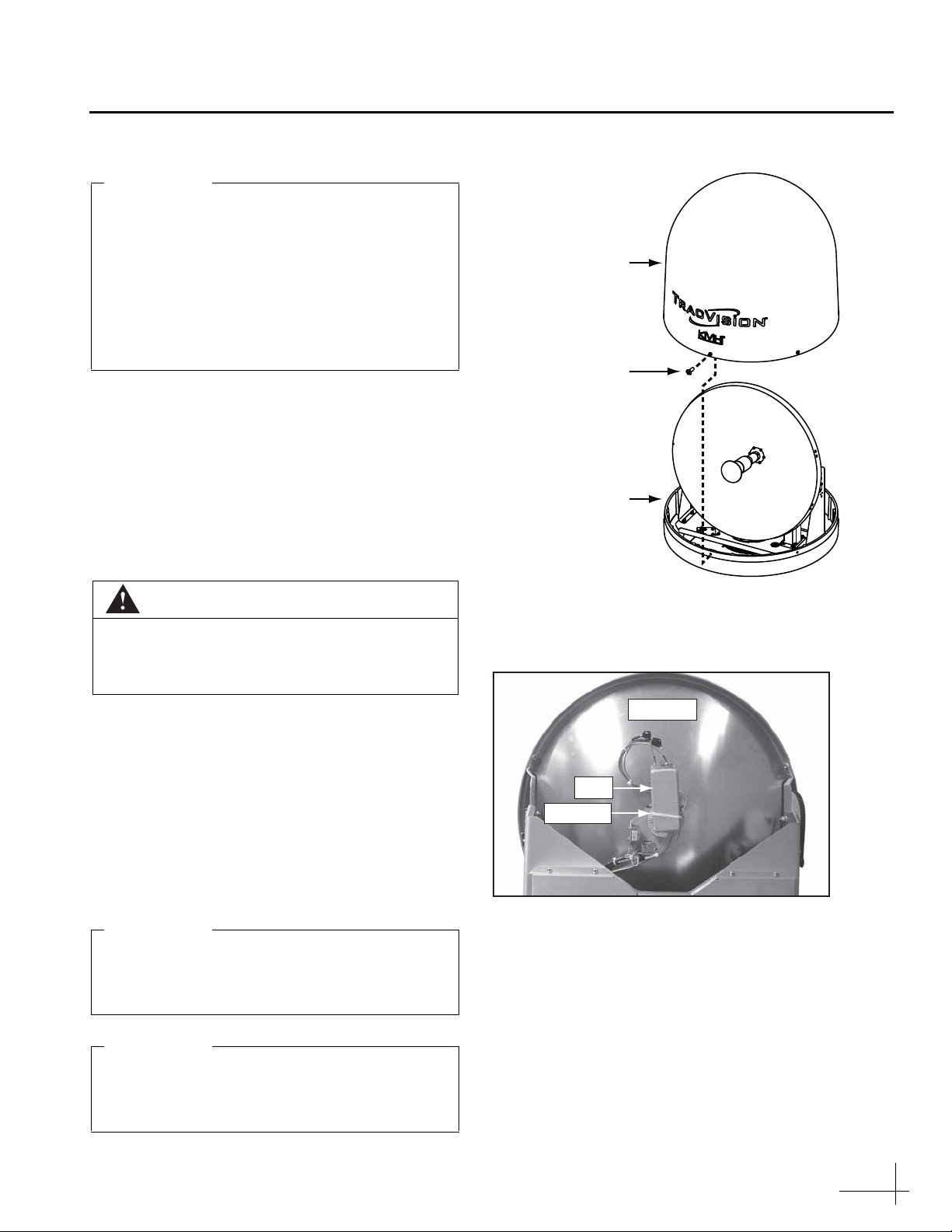
c. Using a #2 Phillips screwdriver, remove the
six #10-32 screws securing the radome to the
antenna’s baseplate (see Figure 1). Remove
the radome and set it aside in a safe place.
d. Cut and remove the tie-wrap securing the RF
cables to the LNB (see Figure 2).
CAUTION
For your own safety, disconnect power from
all system components before you start
working on the antenna.
If your TracVision antenna has a serial
number earlier than 090500117, you should
have received a PCB upgrade kit in addition
to this Tri-Americas LNB kit. Follow the
instructions in the PCB upgrade kit first,
before installing the Tri-Americas LNB. If you
did not receive a PCB upgrade kit, please
contact the KVH Sales Team at 401-847-3327.
IMPORTANT!
#10-32 Screw (x6)
Radome
Baseplate
Figure 1: Removing the Radome
Reflector
LNB
Tie-wrap
Figure 2: Tie-wrap Securing RF Cables to the LNB
Avoid causing sharp bends in cables when
securing or routing cables. Sharp bends or
kinks can degrade antenna performance.
IMPORTANT!
Trim the excess portion of any tie-wraps you
install and collect all tie-wrap trimmings to
avoid damage when the antenna rotates.
IMPORTANT!
Initial Steps

4
If your TracVision system is currently equipped
with a Galaxy or conventional circular LNB, you
must first bypass the inverter PCB (see Figure 3).
The following instructions explain how to bypass
the inverter PCB.
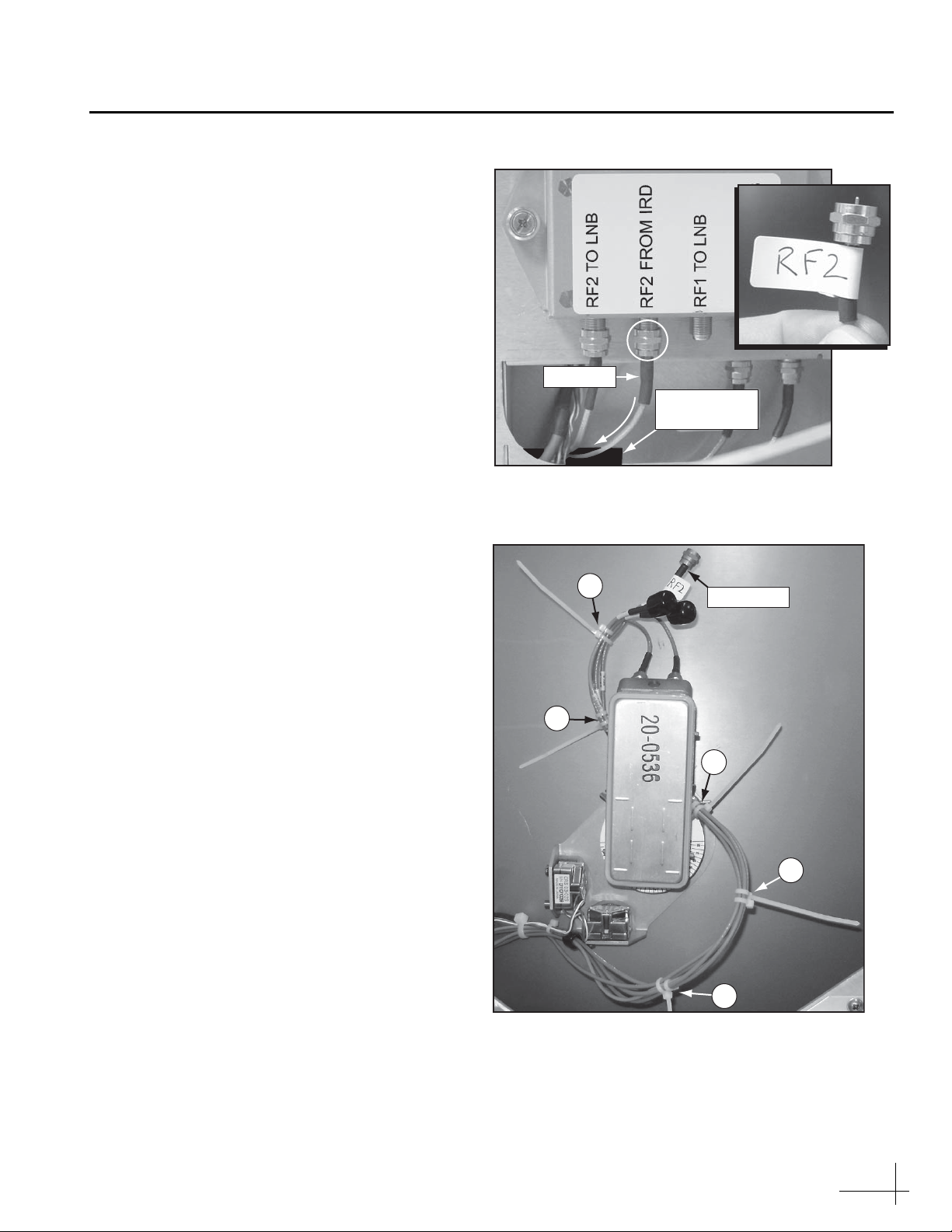
a. Using a 7/16" open-end wrench, disconnect
and remove the RF cable connecting the
inverter PCB to the RF PCB (see Figure 4).
b. Disconnect the RF cable from the inverter
PCB’s “RF1 TO LNB” connector and connect
it to the RF PCB’s “TO LNB” connector (see
Figure 5).
Figure 3: Location of Inverter PCB
Inverter PCB
RF PCB
Behind Cover
Figure 4: Cable Connecting the Inverter PCB to the RF PCB
RF Cable
Figure 5: Moving the RF1 Cable
RF Cable
Bypassing the Inverter PCB
5
c. Disconnect the RF cable from the inverter
PCB’s “RF2 FROM IRD” connector (see
Figure 6).
d. Pass the end of the cable through the cable
access hole and route it to the LNB (see
Figure 6).
e. Apply an “RF2” label to the cable (see
Figure 6).
f. Using five tie-wraps (supplied in the kit),
secure the “RF2”-labeled cable to the cable
bundle at locations 1-5 shown in Figure 7.
Don’t cut the ends of the tie-wraps yet, so you
can easily distinguish these new tie-wraps
from the original tie-wraps.
g. Using wire cutters, cut and remove the
original tie-wraps at locations 1-5 shown in
Figure 7.
h. Cut the excess ends of the new tie-wraps. Be
sure to collect the trimmings from the
antenna.
Cable Access
Hole
RF Cable
Figure 6: “RF2 FROM IRD” Connector on Inverter PCB
RF2 Cable
1
2
4
5
3
Figure 7: Cable Bundle Tie-wrap Locations
Continued Bypassing the Inverter PCB

6
i. Disconnect the RF cable from the LNB’s RF2
connector (see Figure 8).
j. Attach a connector cap (supplied in the kit)
onto the RF cable you disconnected from the
LNB. Using a tie-wrap (supplied in the kit),
secure the cable to the cable bundle as shown
in Figure 9.
NOTE: Leave the other end of this cable connected to
the inverter PCB’s “RF2 TO LNB” connector.
k. Apply an “RF1” label to the RF cable that is
still connected to the LNB (see Figure 10).
l. Connect the “RF2”-labeled cable (from step f)
to the LNB (see Figure 10).
RF Cable
LNB
RF2
Figure 8: RF2 Connector on LNB
Figure 9: Storage Location for Unused RF2 Cable
Tie-wrap
Connector
Cap
RF Cable
Figure 10: RF Connectors on Old LNB
LNB
Continued Bypassing the Inverter PCB
7
Follow these steps to disconnect and remove the
old LNB and install the new Tri-Americas LNB in
its place.
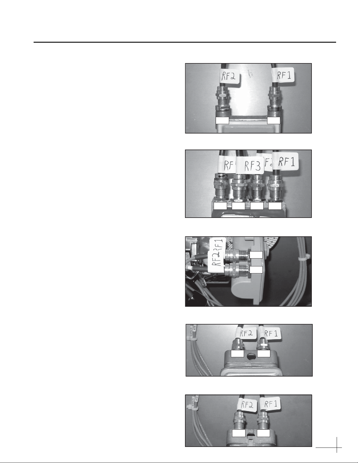
a. Check the RF cables that are connected to the
current LNB. Make sure the cables are labeled
as shown in the associated figure (Figure 11
through Figure 15). Label the cables as
necessary.
b. Disconnect the RF cables from the current
LNB.
RF2 RF1
Figure 11: Linear Dual-output LNB
RF2 RF1RF4 RF3
Figure 12: Linear Quad-output LNB
RF1
RF2
Figure 13: Compact Circular LNB
RF2 RF1
Figure 14: Conventional Circular LNB
RF2 RF1
Figure 15: Galaxy LNB
Installing the Tri-Americas LNB
8
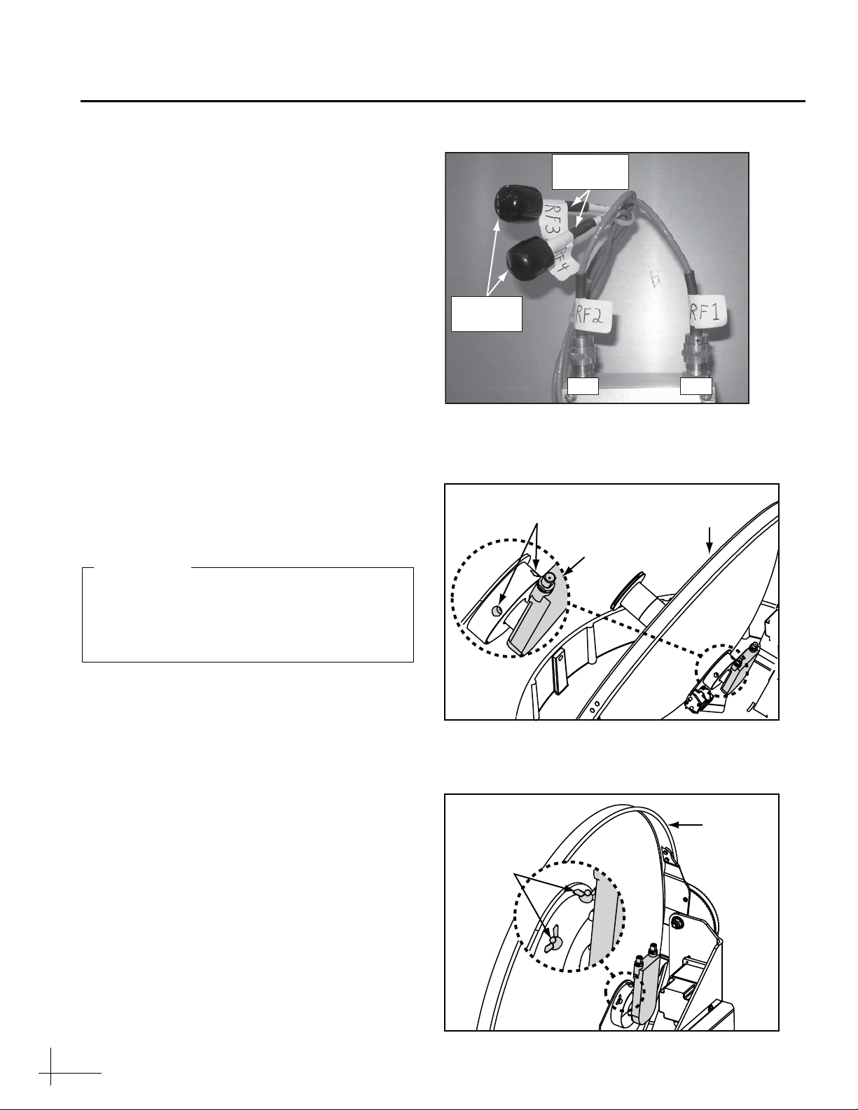
c. Connect the RF1 and RF2 cables to their
corresponding connectors on the Tri-
Americas LNB (Figure 16).
d. If you are replacing a linear quad-output
LNB, apply rubber caps over the connectors
of the unused RF3 and RF4 cables to protect
their center conductors (see Figure 16).
e. If the antenna has a serial number later than
080201076: Using a 2 mm allen hex key,
loosen the two M4 socket set screws securing
the current LNB to the reflector (see
Figure 17).
If your antenna has a serial number earlier
than 080201077, loosen the two wing screws
securing the current LNB to the reflector (see
Figure 18).
f. Remove the old LNB.
g. Insert the new Tri-Americas LNB fully into
the choke feed with the connectors aligned to
the left, as shown in Figure 19 on page 9.
h. If the antenna has a serial number later than
080201076: Tighten the two M4 socket set
screws to secure the LNB in place. Apply
9 in-lbs (1 Nm) of torque, if possible.
If your antenna has a serial number earlier
than 080201077: Tighten the wing screws to
secure the LNB in place.
Connector
Caps
RF2 RF1
RF3 & RF4
Cables
Figure 16: Tri-Americas LNB RF Connectors
M4 Socket
Set Screws Reflector
LNB
Figure 17: LNB Retaining Screws, Newer Antenna
Figure 18: LNB Retaining Screws, Older Antenna
Wing
Screws
Reflector
Orient the Tri-Americas LNB so that its RF
cable connectors are pointing 90° to the left.
The LNB must be positioned in this manner
to ensure proper operation.
IMPORTANT!
Continued Installing the Tri-Americas LNB

9
i. Using a tie-wrap (supplied in the kit), secure
the RF cables to the LNB to prevent them
from getting snagged when the antenna is in
motion (see Figure 19).
j. Reattach the radome (see Figure 1 on page 3).
Tie-wrap
RF Cables
Figure 19: Securing RF Cables to the LNB
Continued Installing the Tri-Americas LNB
10
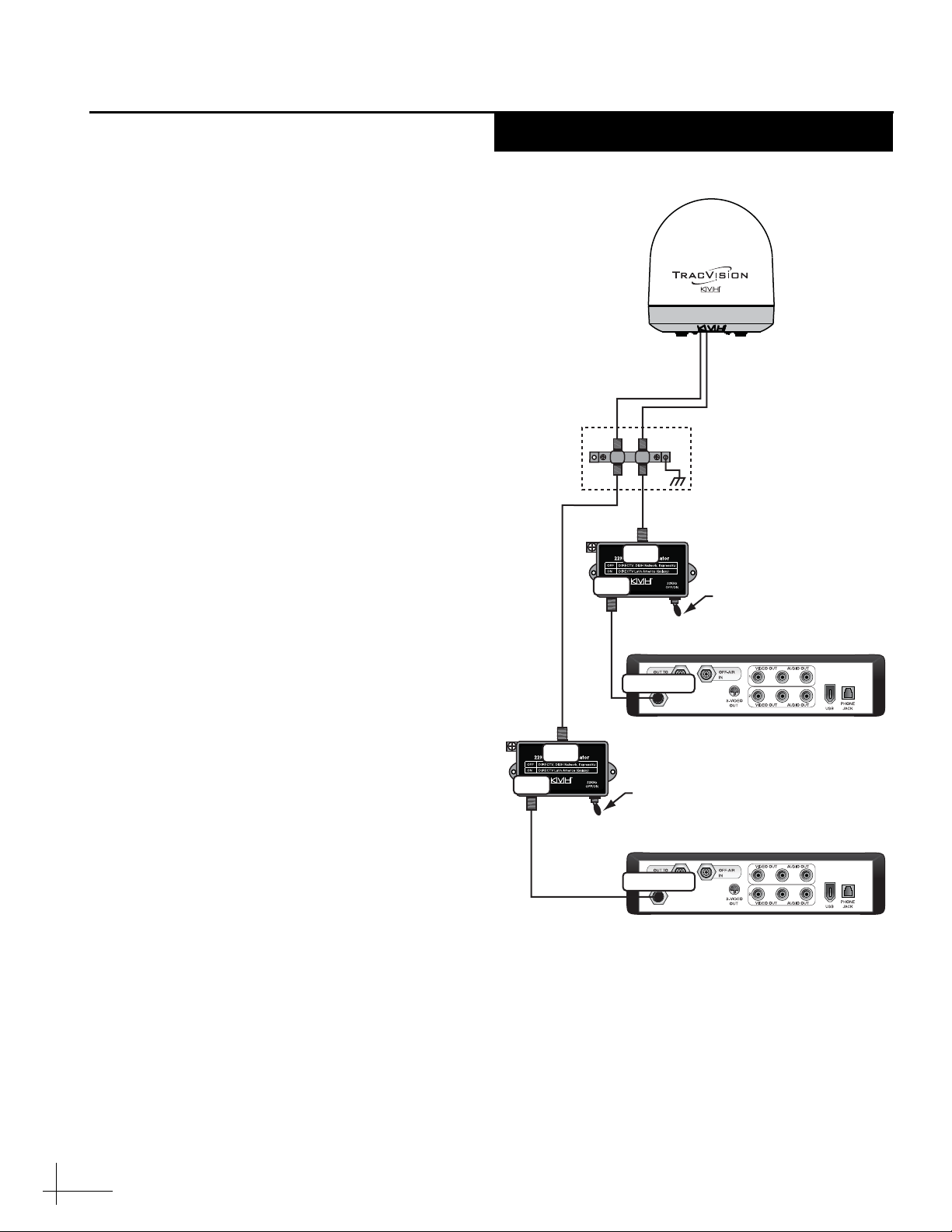
Two 22KHz tone generators are supplied in the
kitpack. Install these devices in-line with the
antenna’s RF cables as explained below. If a
multiswitch is installed, skip to page 11.
a. Disconnect the RF1 cable from the primary
receiver’s “Satellite In” connector.
b. Connect the RF1 cable to the 22KHz tone
generator’s “LNB” connector.
c. Connect a supplied RG-179 RF cable from the
22KHz tone generator’s “REC” connector to
the primary receiver’s “Satellite In”
connector.
d. If you have a second receiver installed, repeat
steps a-c to install the second 22KHz tone
generator between the secondary receiver
and the RF2 cable.
e. Set the 22KHz tone generator’s “22KHz OFF/
ON” switch to the proper position for the
satellite TV service you wish to receive:
OFF = DIRECTV, DISH Network, ExpressVu
ON = DIRECTV Latin America (Galaxy)
If you have two receivers installed, set the switch
on both 22KHz tone generators.
f. Reconnect power to the TracVision system
components.
g. Turn on the TracVision antenna and
configure it to track satellites that are
compatible with the Tri-Americas LNB.
These include DIRECTV, DISH Network
(EchoStar), ExpressVu, or Galaxy. Refer to the
TracVision M5/M7 User’s Guide for details.
Antenna
Secondary Receiver - Optional
Primary Receiver
Thisreceiver controlssatellite selection
RF1RF2
(Optional)
RF1RF2
(Optional)
22KHz Tone Generator
Set switch “ON” for Galaxy
22KHz Tone Generator
Set switch “ON” for Galaxy
Grounding Block
(If Installed)
Satellite In
Satellite In
LNB
REC
LNB
REC
Figure 20: Tone Generator Wiring
Installing the Tone Generators
One or Two Receivers
11
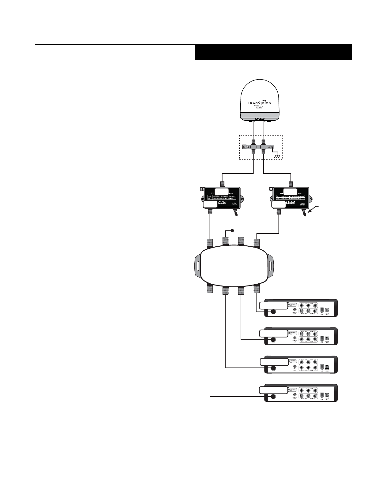
If a multiswitch is installed, follow these steps to
install the supplied 22KHz tone generators.
a. Disconnect the RF1 cable from the
multiswitch’s “13V” connector.
b. Connect the RF1 cable to the 22KHz tone
generator’s “LNB” connector.
c. Connect a supplied RG-179 RF cable from the
22KHz tone generator’s “REC” connector to
the multiswitch’s “13V” connector.
d. Disconnect the RF2 cable from the
multiswitch’s “18V” connector.
e. Connect the RF2 cable to the second 22KHz
tone generator’s “LNB” connector.
f. Connect a supplied RG-179 RF cable from the
second 22KHz tone generator’s “REC”
connector to the multiswitch’s “18V”
connector.
g. Set the “22KHz OFF/ON” switch on both
22KHz tone generators to the proper position
for the satellite TV service you wish to
receive:
OFF = DIRECTV, DISH Network, ExpressVu
ON = DIRECTV Latin America (Galaxy)
h. Reconnect power to the TracVision system
components.
i. Turn on the TracVision antenna and
configure it to track satellites that are
compatible with the Tri-Americas LNB.
These include DIRECTV, DISH Network
(EchoStar), ExpressVu, or Galaxy. Refer to the
TracVision M5/M7 User’s Guide for details.
22KHz Tone
Generators
Set switches
“ON” for Galax
y
Satellite In
Satellite In
Satellite In
Receiver #3
Receiver #2
Receiver #1
Receiver #4
Satellite In
RF2 RF1
RF2 RF1
AC Power
13V
SAT
Rx4
ANT
IN
Rx3
DC
20V
Rx2
Rx1
18V
SAT
Grounding Block
(If Installed)
LNB
REC
LNB
REC
Figure 21: Tone Generator Wiring, Multiswitch Configuration
Installing the Tone Generators
Three or More Receivers
Table of contents


