Tricel Duos P6 User manual

1

2
Table of contents
1.Health and safety precautions: 3
1.1 General: 3
1.2 Electrical/maintenance 3
1.3Installation: 3
2. Transporting, unloading and storage of tanks: 4
3. Introduction: 6
4. The wastewater purification process: 7
4.1 Stage 1: Existing primary settlement chamber: 7
4.2 Stage 2:Aeration (treatment) chamber: 7
4.3 Stage 3:Final settlement chamber: 7
5. Plant dimensions: 8
6. Plant drawings: 10
7.Technical drawings of Tricel pumped plant: 14
8.Lid locking points: 14
9.Manhole risers (deep inverts): 15
10. Installation: 16
10.1 Pre-installation tank inspection: 16
10.2 Quick installation guidelines: 17
10.3 Detailed installation information: 18
10.3.1 Excavation size: 19
10.3.2 Eexcavation dept: 20
10.3.3 Loadings: 21
10.3.4 Control of groundwater 21
10.4 Gravel installation: 21
10.4.1 Tank base/plinth: 22
10.4.2 Installing onto the base/plinth: 22
10.4.3 Backfilling dry site 22
10.5 Concrete installations: 23
10.5.1 Tank base/plinth: 23
10.5.2 Installing onto the base/plinth: 23
10.5.3 Backfilling a wet site: 24
10.6 Plinth and backfill specifications: 25
10.6.1 Gravel backfill specifications 25
10.6.2 Concrete backfill specifications: 26
10.6.3 Top soil 26
11. Electrical installation: 27
12. Plumbing the system: 27
13. Ancillary installation notes: 28
13.1 Ventilation: 28
13.2 Control housings: 28
13.3 Access: 28
14. Plant operation: 29
15. Disposal of treated water: 29
16. Maintenance: 30
16.1 Regular maintenance: 30
16.2
16.2.1 Yearly service (available from your supplier): 30
16.3 Production of sludge: 31
17. Operation conditions: 32
18. Troubleshooting: 33
19. Certification: 37
TTM T103 Rev04 –08 April 2014

3
It is
i
mpo
r
t
an
t
to read
t
he
full technical
and installation
guideprior to installation.
T
h
i
s
do
c
umen
t
should
be
r
e
t
a
i
ned
for
t
he
lifetime of
t
he
p
r
odu
c
t
and in
t
he
e
v
en
t
of
change
o
f
ownership
be
t
r
an
s
f
e
rr
ed
to
t
he
new
o
w
ne
r
.
Precaution
Prior to installation, please consider finished garden level when installing the plant. If you envisage that a
manhole riser/extension may be required to ensure manhole lid remains above finished ground level, the plant
must be installed with the appropriate excavation foundation and backfill to accommodate the riser. Please refer
to page 18 for manhole riser details.
1.
Health
and safety
p
re
c
au
ti
on
s
:
As safety and security are of vital importance, the following aspects are
critical.
1.1 General
:
•
Ensure the Duos plant is only installed after a functioning correctly sized septic tank
Ensure that all the information contained in this manual is adhered to at all times
•
Treated wastewater is not suitable for human consumption.
•
It’s important that locks are fitted to the lid to prevent accidental access.
•
Manholes are rated to 125kg and are for pedestrian use only
•
Never enter a tank, unless qualified to do so.
•
Naked flames shall not be used in the vicinity of the tank due to the danger of combustion.
•
The manhole covers shall never be left off an unattended tank. Always lock the cover of the
system when work is completed
•
Sewage and sewage effluent can carry micro-organisms and gases harmful to human health. Any
person carrying out work on the system must be appropriately trained. Suitable protective
clothing; including gloves, goggles should be worn at all times. Always remove contaminated
clothing and protective equipment after working with sewage treatment plants. Wash hands and face
prior to eating, drinking or smoking.
1.2 Electrical/
M
a
i
n
t
enan
c
e:
•
All electrical work to be carried out by competent persons using suitable materials for the application.
•
Do not open the Tricel® Duos cover without firstly isolating the mains power.
•
Electrical work must be carried out strictly to the manufacturer’s instructions and to the
relevant national rules for electrical installations.
•
When working with machinery / electrical equipment, proximity of water shall be noted.
Electrical equipment shall not be wet when working with it.
•
There is potential danger when de-sludging and therefore this shall never be done alone

4
1.3 Installation
:
•
Excavation work should be planned with due regard to health and safety requirements.
•
Excavation should either be shored or battered back to a “safe” angle.
•
Use appropriate lifting equipment
•
Care should be taken around grounds work machinery
•
Keep proper footing and balance at all time
2. Transportation, unloading and storage of tanks
:
1. Tanks must be held down during transportation using nylon straps, do not use cables or chains to
secure tanks. Do not over tighten straps to cause deformation of the tank shell. Do not drop or roll tanks from
the truck.
2. Move tanks only by lifting and setting, do not drag or roll.
3. Always set the tank(s) on flat smooth ground free from debris etc. To prevent movement, tanks may need to
be tied down and chocked.
4. Tanks are best lifted by a machine and webbing lifting straps –do not use chains or wire ropes in contact
with the tank. Ensure tank is empty when lifting. Care is needed to control the lift to ensure the tank is not
damaged.
5. Tanks from one to four modules (4.6m) in length should be lifted using the eyebolts on the tank.
To ensure the angle of the sling is not greater than 60o, as per option 1, the following sling lengths are
required:
Length of tank
Minimum length of sling
2.1
2.1
2.6
2.6
3.1
3.1
3.6
3.6
4.6
4.6

5
Ensure sufficient lifting height can be achieved and is available on site. If not a lifting bar as per option
2 is required.
Option 1* Option 2*
6. Tanks which are greater than 4 modules (4.6m) in length should be lifted using the slings provided
as per option 3, shown below.
Option
3*
Ensure sufficient lifting height can be achieved and is available on site available. If not a lifting bar as per
option
4 is required.
Option 4*
Ensure the slings are positioned at a joint on the tank, firmly secured and the load is evenly
balanced.
*Typical lifting examples

6
3.
Introduction
:
Tricel
Duos wastewater treatment plants are manufactured from Sheet Moulding Compound (SMC) ensuring a
durable and strong product. The Tricel Duos is manufactured in modular components and these modules are
fabricated together to make different size tanks.
The Tricel Duos Submerged aeration system is suitable for domestic and light commercial applications. These
plants use a simple, proven technology, comprising of 2 treatment zones. In each zone a different stage of
the treatment occurs. All Duos plants must be preceded by a functioning suitably sized septic tank.

7
4. The wastewater
purification
p
ro
c
e
ss
:
4.1 Stage 1: Existing
Primary
settlement
c
hambe
r
:
The wastewater is introduced into the primary chamber which must proceed the Duos system (not
included). Settlement occurs when the heavier solids, drop out of the wastewater and settle to the bottom
of the tank to create sludge and when lighter solids, like fats or oils, float to the top of the water to create
a scum. Good practice is to install a filter at the outlet of the existing septic tank to reduce suspended solids
from the effluent.
.
4.2 Stage 2:
A
e
r
a
t
i
on
(
t
r
ea
t
men
t
)
c
hambe
r
:
Stage 2 takes place in the aeration chamber where submerged aeration combines the principles of the bio
film and activated sludge processes. Masses of naturally occurring bacteria inhabit specially designed
plastic filter media. The filter media, has large surface area, and is supported within the aeration zone. As
the liquid flows slowly through the filter media the bacteria feed on the waste removing them from the
liquid. These bacteria are sustained with air, which is continuously supplied from a purpose built low
pressure, high volume air blower in the top section of the unit. The air is delivered through a diffused
aeration system, which break the air into bubbles as they are dispersed through the aeration zone. The
continuous circulation of the wastewater within the aeration zone means that the wastewater is passed
through the filter media over and over, thus ensuring very high treatment efficiency. The purified liquid is
then passed into the final settlement zone.
4.3 Stage 3:
Finalsettlement
c
hambe
r
:
As the liquid flows from the aeration zone into the final settlement zone small quantities of bacteria may be carried
with the liquid. Before discharge from the system, these solids must be separated from the liquid. With the velocity
of the liquid slowed down and the flow path maximized the bacteria settles to the bottom of the tank as sludge.

8
5.
Plant
D
i
men
s
i
on
s
:
Tricel Duos wastewater treatmentplants.
Design population
6 person
8 person
10 person
12 person
18 person
24 person
Nominal inlet/outlet pipe diameter
mm
110
110
110
110
110
150
Overall length
m
1.6
1.6
2.1
2.6
3.1
3.6
Overall width
m
1.64
1.64
1.64
1.64
1.64
1.64
Overall height
m
2.24
2.24
2.24
2.27
2.27
2.27
Inlet invert to base
m
1.375
1.375
1.375
1.375
1.375
1.35
Outlet invert to base
m
1.3
1.3
1.3
1.3
1.3
1.3
Inlet invert to ground level
m
0.535
0.535
0.535
0.535
0.535
0.56
Outlet invert to finished ground level
m
0.61
0.61
0.61
0.61
0.61
0.61
Height above finished ground level
m
0.32
0.32
0.32
0.32
0.35
0.35
Weight empty**
kg
200
250
250
300
350
400
BOD Load (max)
kg/day
0.36
0.48
0.6
0.72
1.08
1.44
Design flow rate (max)
liters/day
900
1200
1500
1800
2700
3600
No of persons
2-6
3-8
4-10
4-12
6-18
8-24
Air blower rating (mean)
watts
60
100
100
100
200
200
**Allow 100kgs extra for lifting purposes

10
D
e
s
i
gn
popu
l
a
t
i
on
30
perso
n
36
perso
n
42
perso
n
50
perso
n
Nominal inlet/outlet pipe
diameter
mm
150
150
150
150
Overall length
m
4.6
5.6
5.6
6.6
Overall width
m
1.64
1.64
1.64
1.64
Overall height
m
2.27
2.27
2.27
2.27
Inlet invert to base
m
1.35
1.35
1.35
1.35
Outlet invert to base
m
1.3
1.3
1.3
1.3
Inlet invert to ground level
m
0.56
0.46
0.46
0.46
Outlet Invert to ground level
m
0.61
0.61
0.61
0.61
Height above ground level
m
0.35
0.35
0.35
0.35
Weight empty**
kg
550
650
700
750
Design flow rate (max)
liters/day
4500
5400
6300
7500
BOD load (max)
kg/day
1.8
2.16
2.52
3
No. of persons
10-30
13-36
14-42
16-50
Air blower rating (mean)
watts
200
200+ 80
200 x 2
200x2
**Allow 100kgs extra for lifting purposes
6.
Plant
D
ra
w
i
ng
s
:
T
r
i
c
e
l
Duos 6 person
g
r
a
v
i
t
y
plant
:

11
T
r
i
c
e
l
Duos 8 person
g
r
a
v
i
t
y
plant
:
TricelDuos 10 person
g
r
a
v
i
t
y
plant
:
TricelDuos 12 person
g
r
a
v
i
t
y
plant
:

12
TricelDuos 18 person
g
r
a
v
i
t
y
plant
:
TricelDuos 24 person
g
r
a
v
i
t
y
plant
:
TricelDuos 30 person
g
r
a
v
i
t
y
plant
:

13
TricelDuos 36 person
g
r
a
v
i
t
y
plant
:
Tricel Duos 42 person
g
r
a
v
i
t
y
sys
t
em
TricelDuos 50 person
g
r
a
v
i
t
y
sys
t
em:

14
7. Technical drawing of Tricel Duos pumped plant:
All plants are available with a pumped outlet option. The pump can be housed in the final settlement chamber
of the system. The standard pump option has a 1 ½”connection on the outside of the plant. Our standard
pump specification is outlined below. Other pump options are available to customer specifications.
Standard pump specification:
•
Min discharge rate 60l/min
•
Continuous duty with
35°C
liquids & fully
submerged
•
Dry motor (class F insulation)
•
IP68 protection
•
Max immersion 5m
•
Single phase 220-240 V 50 Hz 2 poles
•
0.55 to 1.1 kW for single phase
•
Rp 1 ½”delivery port (female gas)
•
Handles solids up to 35mm
F
I
N A
L
S E T T L E M E N
T
T A N K
S
8.
Lid locking
po
i
n
ts
:
All manholes should be locked for safety. Tanks are supplied with 3 optional locking points, as shown below.
All these points should be locked with a suitable locking device to prevent unauthorized access. Locking
devices are not supplied.

15
9.
M
anho
l
e
risers
–
(deep
i
n
v
e
rts
)
:
Manhole risers are available for deeper installation requirements
)r 250mm manhole risers require installation suitable for the site condition.
)r 500mm* & 750mm* manhole risers require a complete concrete installation –See section 10.5.
)r Max manhole riser is 750mm
Never place the covers
of the
tank below ground
level.
Do not allow ground
water
enter the
system
Only Tricel Duos manhole
risers
should be
used
Manhole risers are
available
as
standard
250mm
500mm
750mm
*Plants with a manhole riser of 500mm or 750mm must have a concrete installation. 500mm and 750mm
risers cannot be retrofitted unless the correct installation is in place.

16
10.
I
n
s
ta
ll
a
t
i
on:
All installations must be “fit for purpose” to suit the on-site conditions, which will vary from site to site. This is
the responsibility of the onsite contractor.
The Tricel Duos is suitable for a maximum manhole riser of 750mm which gives a maximum inlet invert of
1310mm, as
per picture. The Tricel Duos is not suitable where a deeper installation is required.
10.1
P
r
e
–
i
n
s
t
a
ll
a
t
i
on
tank
i
n
s
pe
c
t
i
on:
•
Tanks should be visually inspected for damage which may have occurred during transport prior to
installation. Any damage should be notified to the delivery driver and/or to your supplier. Do not
attempt to carry out any unauthorised repairs, as this will invalidate the warranty on the tank
•
Once the tank has been installed, we cannot accept any claims for damage

17
10.2Quickinstallation
gu
i
de
li
ne
s
:
A dry site is one where the water table never rises higher than the base of the Tricel Duos
tank. A wet site is one where the water table may rise higher than the base of the Tricel
Duos tank. The tank should never be installed where ground water can rise higher than the
inlet pipe.
Important
Inlet invert to finished ground level must be determined to ensure the correct installation
procedure is followed. See section 9.
Guidelines
Dry Site
Wet Site
The tank should be located as clode to the septic tank as possible
considering topography and pipe work levels. The tank location should
be specified by a suitably qualified person. The plant must be installed
correctly to ensure surface or ground water does not enter the system.
Never roll the tank. Tanks shall be lifted into position in accordance
with supplier’s instructions. See section 2
Dig a hole 500mm larger than the plant dimensions in plan. The depth
of the hole will be determined by the inlet pipe level.
If the plant contains more than one tank a stepped installation is
required
Remove any soft spots or boulders of significant size from the base
or sides of the excavation.
Ground water must be pumped to give a dry excavation and
excavation lined with polythene.
Determine the type of backfill by taking into account, ground
conditions (wet or dry) and finished ground level (determine if, and
height of riser required). The site engineer should specify the site
conditions.
A base is then formed using compacted gravel and this must be flat
and level.
A base is constructed of a 50mm layer of compacted gravel covered
with a 250mm layer of 25n semi dry concrete.
Ensure gravel/concrete is clean and contains no large materials.
Lift tank into position and align height for connecting pipe work.
Ensure correct inlet and outlet orientations of the plant, which may

18
Contain 1 or more tanks.
Ensure that each tank is 100% level.
Connect pipe work, as required.
Ballast the tank with water. Refer to detailed installation
Commence gravel backfilling in 300mm layers approximately up to
50mm over the cylindrical body of the tank, ensuring tank and any
pipe work is properly supported.
Commence concrete backfilling in 300mm layers approximately up to
the pipe work level, ensuring tank and any pipe work is properly
supported.
Continue backfilling with gravel up to 50mm over the cylindrical body
of the tank
Mount and seal any turret extensions.
Complete backfilling with topsoil up to the max ground level line
indicated on the plant. The surrounding finished ground level
should never be higher than the “max ground level line”.
Compact evenly around the tanks to ensure it’s is properly supported.
An access chamber should be installed before and after the tank
for sampling and to assist in clearing possible blockages
If sewage consists of high quantities of grease a grease trap should be
installed prior to the plant.
Note: The option of a reinforced concrete slabs or deadman anchor may also be used on wet sites. This should
be designed by an on-site structural engineer to suit site conditions.
10.3
D
e
t
a
il
ed
installation
i
n
f
o
r
ma
t
i
on:
The Tricel Duos should not be installed in an area subject to
flooding or
excessive water runoff. The area
around the Tricel Duos should be adequately drained, to permanently remove ground water and surface
water from the proximity of the tank. The Tricel Duos system is not suitable to be used in water logged sites,
where the ground water may rise above the inlet level.

19
10.3.1 Excavation size:
Suitably sized equipment will be required to excavate the hole and to lift the system into
place.
Installation depends on on-site conditions, water, slopes, location etc. Excavation should be planned
with due regard to health and safety requirements. The excavation should allow a minimum 250mm
clearance between the tank and the excavation wall or face of shoring. A minimum of 500mm is
also required between adjacent tanks. Unstable ground with excessive sand, peat swamps etc. may
require larger excavations. The excavation should be maintained dry by pumping or whatever suitable
means.
Total excavation: {Width. + 500mm} x {Length +
500mm} Excavation depth:
Dry Site: Allow 250mm for tank
base/plinth. Wet Site: Allow 300mm for
tank base/plinth
Please note max manhole riser is 750mm
Tank Size
Excavation
Size
Tank A (
m
)
6 person
2.1 x 2.15
8 person
2.1 x 2.15
10 person
2.6 x 2.15
12 person
3.1 x 2.15
18 person
3.6 x 2.15
24 person
4.1 x 2.15
30 person
5.1 x 2.15
36 person
6.1 x 2.15
42 person
6.1 x 2.15
50 person
7.1 x 2.15
20
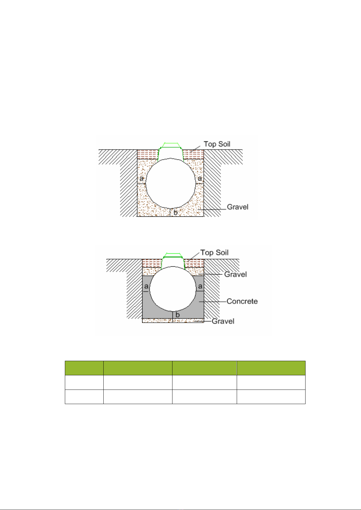
10.3.2 Excavation depth:
The excavation depth is determined by the inlet and outlet pipe, invert levels relative to the bottom of
the tank, and allowing for the minimum base thickness shown. Dimension details of the tank are shown
on the relevant drawing, given in section 6. Ground instability e.g. running sand may necessitate over-
excavation and stabilization with hard core or blinding concrete.
Dry
site
Wet
site
Tank Width. in mm
“a” minimum in mm
“b”minimum in mm
Dry Site
1650
250
250
Wet site
1650
250
300

21
10.3.3 Loadings:
If the tank is installed in an area where traffic or other superimposed loadings can be applied, consult a
structural engineer for the design of a reinforced concrete slab to prevent the load being transmitted to
the tank (or its concrete surround). If this slab is constructed immediately above the tank, it should
be separated from the concrete surrounding the tank by a compressible material. Installation guidelines
are available on www.ie.tricel.eu.
10.3.4 Control of groundwater:
During installation tanks must not be subjected to buoyant
forces.
Incorrectly installed tanks that are subject to movement, rotation or floatation may become damaged,
for which we cannot accept liability.
Contact a qualified engineer if there are difficulties on site due to adverse water
logging.
10.4 Gravel
i
n
s
t
a
ll
a
t
i
on:
A gravel surround can be used in dry site conditions if the inlet invert is less than 810mm (maximum
250mm riser).
A dry site is one where the water table never rises higher than the base of the Tricel Duos tank.
This manual suits for next models
9
Table of contents
Popular Tank Equipment manuals by other brands

JohnDow Industries
JohnDow Industries JDI-AFT106 Operator's manual

Regulus
Regulus PS 500 E Assembly, installation and operation instructions

RKI Instruments
RKI Instruments RI-215A Operator's manual

Micron
Micron Spraydome Series instruction manual

Alfalaval
Alfalaval HTC instruction manual

Kemper
Kemper FK-5 operating instructions


