Regulus RBC 200 User manual

www.regulus.eu
RBC 200 - 3000
RBC 200 - 3000
EN
Installation and Operation Manual
HOT WATER STORAGE TANKS
RBC 200, RBC 300, RBC 400, RBC 500, RBC 750,
RBC 1000, RBC 1500, RBC 2000, RBC 2500 a RBC 3000

│2
REGULUS - RBC Hot Water Storage Tanks - www.regulus.eu
CONTENTS
1 Description ....................................................................................................................................... 3
1.1 Models ................................................................................................................................. 3
1.2 Tank protection ..................................................................................................................... 3
1.3 Thermal insulation ................................................................................................................ 3
1.4 Connection points on the tank ............................................................................................. 3
1.5 Packaging ............................................................................................................................ 3
2 General Information ......................................................................................................................... 4
3 Operation .......................................................................................................................................... 4
4 Technical Data and Dimensions of RBC Models ......................................................................... 5
5 Typical Installation Examples ......................................................................................................... 7
6 Installation and Commissioning .................................................................................................... 9
6.1 Connection to heat sources ................................................................................................ 9
6.2 Connection to a solar thermal system ................................................................................. 9
6.3 Heating element installation ................................................................................................ 9
6.4 Connection to water mains ................................................................................................. 9
6.5 Electronic anode rod installation ......................................................................................... 9
6.6 Commissioning .................................................................................................................... 10
7 Tank Insulation ................................................................................................................................. 10
8 Maintenance, Replacement of Magnesium Anode Bar ................................................................. 11
9 Disposal ............................................................................................................................................ 11
10 Warranty ............................................................................................................................................ 11

3 │
REGULUS - RBC Hot Water Storage Tanks - www.regulus.eu
1 - Description
RBC Hot Water Storage Tank (further “tank“) with one enameled heat exchanger with a G 5/4” connection (e.g.
for connecting a solar thermal system), enabling installation of an electric heating element and also another el.
heating element or a finned tube heat exchanger into the flange of the lateral inspection hole.
In order to reach proper working of the tank, it is necessary to design optimum hydraulics of the whole system,
i.e. position of circulation pumps for sources and heating circuits, valves, non-return valves etc.
1.1 - Models
Ten models of 214, 297, 408, 515, 767, 887, 1492, 2006, 2509 a 2841 l capacity enabling installation of an
electric heating element or another heat source.
1.2 - Tank protection
Enameled inner surface and coil guarantee long service life. Enamel is done according to DIN 4753 standard.
Further qualitative improvement is reached thanks to a magnesium anode installed inside the tank (even more
anode rods are installed in tank of a bigger volume). From RBC 400 upwards each tank has 2 anode rods.
The RBC 3000 tank has 3 anodes.
1.3 - Thermal insulation
RBC 200 to 500 tanks are supplied with a hard polyurethane insulation 55 mm thick with a white PVC surface.
RBC 750 and 1000 tanks are supplied with a hard polyurethane insulation 75 mm thick with a white PU leather
surface. RBC 1500, 2000, 2500 and 3000 tanks have the insulation 100 mm thick. The insulation can be detached
for easier handling.
1.4 - Connection points on the tank
2× lateral with G 5/4“ inner thread, of the heating heat exchanger circuit
2× lateral with G 5/4“ inner thread (RBC 200, RBC 300 and RBC 400 with G 1“ inner thread, RBC 1500 - 3000
with G 2“ inner thread) for cold water inlet and hot water outlet
2× lateral with G 1/2“ inner thread, for a temperature sensor and thermometer
1× lateral with G 1“ inner thread (RBC 200, RBC 300 and RBC 400 with G 3/4“ inner thread), for circulation
1× top with G 5/4“ inner thread, for a magnesium anode rod
1× lateral with G 6/4“ inner thread, for an el. heating element
1× flange for the lateral inspection hole
1.5 - Packaging
Tanks are delivered standing, each screwed to its pallet, packed in bubble wrap. It is forbidden to transport and/
or store the storage tanks in a horizontal position.

│4
REGULUS - RBC Hot Water Storage Tanks - www.regulus.eu
3 - Operation
This tank is designed for operation in closed pressure circuits. Hot water is heated in the integrated hot-water
heat exchanger inside the tank by several possible heat sources like various kinds of heating boilers, renew-
able energy sources (heat pumps, solar collectors). An electric heating element can be installed into the tank for
DHW auxiliary heating.
Hot water temperature should be set to 60-65 °C. This temperature guarantees the best operation and at the
same time, it prevents formation of Legionella bacteria.
2 - General Information
The appliance shall be installed by a qualified person according to valid rules and Manufacturer‘s Instructions.
This Manual is an integral and important part of the product and must be handed over to the User. Read carefully
the instructions in this Manual as they contain important information concerning safety, installation, operation
and maintenance. Keep this Manual for later reference.
Using the tank for other purposes than stated in this Manual is forbidden and the manufacturer accepts no
responsibility for damage caused by improper or wrong use.

5 │
REGULUS - RBC Hot Water Storage Tanks - www.regulus.eu
4 - Technical Data and Dimensions of RBC
Models
Tank code ........................................................................................... a
Tank total volume ............................................................................... b
Heat exchanger volume ..................................................................... c
Heat exchanger surface area ............................................................. d
Empty weight (transport) .................................................................... e
Max. working temperature - tank ....................................................... 95 °C
Max. working temperature - heat exchanger ..................................... 110 °C
Max. working pressure - tank ............................................................. 10 bar
Max. working pressure - heat exchanger ........................................... 10 bar
DHW heating ∆t =35 °C (80/60 - 10/45) - heat exchanger ................. f
V
ø K
ø L

│6
REGULUS - RBC Hot Water Storage Tanks - www.regulus.eu
Model RBC200 RBC300 RBC400 RBC500 RBC750 RBC1000 RBC1500 RBC2000 RBC2500 RBC3000
Tank code a 3252 3253 6479 6480 4037 4038 16710 16711 12420 8477
Tank total volume [l] b 214 297 408 515 767 887 1492 2006 2509 2841
Volume of the heat
exchanger [l] c 10 11 12 15 19 19 26 29 30 32
Surface area of the heat
exchanger [m2]d 1.5 1.7 1.9 2.5 3.4 3.5 4.2 4.5 4.8 5.2
Empty weight [kg]
(transport) e 82 109 131 163 240 262 394 461 583 642
DHW heating ∆t=35 °C
(80/60 - 10/45) [l/h] ([kW]) f590
(24)
670
(27)
740
(30)
990
(40)
1340
(54)
1380
(56)
1660
(67)
1780
(72)
1900
(77)
2050
(83)
Static loss [W] 67 81 96 102 113 121 153 180 329 354
Dimensions [mm] V 1265 1710 1655 1785 1870 2120 2285 2550 2680 2980
ø K 610 610 710 760 950 950 1200 1300 1400 1400
ø L 500 500 600 650 790 790 1000 1100 1200 1200
Tipping height mm 1410 1820 1810 1950 2100 2330 2590 2870 3030 3300
Magnesium anode rod G5/4“
Code
A1 4025 448 4025 4025 464 3698 3698 3698 3698 3698
Magnesium anode rod G5/4“ A2 - - 4025 4025 448 448 448 464 464 464
Magnesium anode rod G5/4“ A3 - - - - - - - - - 464
Magnesium anode rod G5/4“,
chain type * - - - - 13112 13112 13112 13112 13112 13112
* Possible replacement of anode A1
CONNECTIONS
RBC200 RBC300 RBC400 RBC500 RBC750 RBC1000 RBC1500 RBC2000 RBC2500 RBC3000
pos. conn. height
[mm] conn. height
[mm] conn. height
[mm] conn. height
[mm] conn. height
[mm] conn. height
[mm] conn. height
[mm] conn. height
[mm] conn. height
[mm] conn. height
[mm]
DHW heating
W1 G 1“ F 67 G 1“ F 67 G 1“ F 79 G 5/4“ F 175 G 5/4“ F 220 G 5/4“ F 220 G 2“ F 315 G 2“ F 340 G 2“ F 430 G 2“ F 430
W2 G 1“ F 1164 G 1“ F 1609 G 1“ F 1541 G 5/4“ F 1595 G 5/4“ F 1590 G 5/4“ F 1840 G 2“ F 1935 G 2“ F 2210 G 2“ F 2250 G 2“ F 2550
W3 G 3/4“ F 915 G 3/4“ F 1140 G 3/4“ F 1204 G 1“ F 1315 G 1“ F 1350 G 1“ F 1545 G 1“ F 1460 G 1“ F 1650 G 1“ F 1740 G 1“ F 2040
El. heating elements
E1 G 6/4“ F 797 G 6/4“ F 986 G 6/4“ F 980 G 6/4“ F 1150 G 6/4“ F 1050 G 6/4“ F 1050 G 6/4“ F 1255 G 6/4“ F 1310 G 6/4“ F 1400 G 6/4“ F 1400
Control and safety
C1 G 1/2“ F 593 G 1/2“ F 653 G 1/2“ F 689 G 1/2“ F 825 G 1/2“ F 775 G 1/2“ F 870 G 1/2“ F 943 G 1/2“ F 985 G 1/2“ F 1075 G 1/2“ F 1075
TG 1/2“ F 997 G 1/2“ F 1431 G 1/2“ F 1385 G 1/2“ F 1400 G 1/2“ F 1430 G 1/2“ F 1680 G 1/2“ F 1825 G 1/2“ F 2090 G 1/2“ F 2130 G 1/2“ F 2430
Solar thermal system
X1 G 5/4“ F 758 G 5/4“ F 848 G 5/4“ F 874 G 5/4“ F 1075 G 5/4“ F 970 G 5/4“ F 970 G 5/4“ F 1180 G 5/4“ F 1160 G 5/4“ F 1250 G 5/4“ F 1300
X2 G 5/4“ F 263 G 5/4“ F 263 G 5/4“ F 314 G 5/4“ F 320 G 5/4“ F 385 G 5/4“ F 385 G 5/4“ F 470 G 5/4“ F 460 G 5/4“ F 550 G 5/4“ F 550
Flange
L1 8 x M10 257 8 x M10 257 8 x M10 268 8 x M10 335 8 x M10 400 8 x M10 400 8 x M10 520 8 x M10 550 8 x M10 640 8 x M10 640
Magnesium anode rod
A1 G 5/4“ F 1240 G 5/4“ F 1685 G 5/4“ F 1656 G 5/4“ F 1742 G 5/4“ F 1790 G 5/4“ F 2045 G 5/4“ F 2205 G 5/4“ F 2470 G 5/4“ F 2600 G 5/4“ F 2900
A2 - - - - G 5/4“ F 268- G 5/4“ F 335 G 5/4“ F 400 G 5/4“ F 400 G 5/4“ F 520 G 5/4“ F 550 G 5/4“ F 640 G 5/4“ F 640
A3 - - - - - - - - - - - - - - - - - - G 5/4“ F 1640

7 │
REGULUS - RBC Hot Water Storage Tanks - www.regulus.eu
Example I.
With solar thermal collectors
5 - Typical Installation Examples
KEY
1 – RBC hot water storage tank
2 – CSE SOL solar pump station
3 – solar expansion vessel
4 – solar collectors
5 – pump station for DHW recirculation – CSE TVMIX ZV
6 – safety kit for HW storage tank
7 – DHW expansion vessel
8 – el. heating element
SV – cold water
TV – hot water
CV – hot water recirculation
KK – ball valve
ZV – check valve
AOV – automatic air vent valve
PTR – pressure temperature relief valve
REDV – pressure reducing valve (optional)
VK – drain valve
SVE – expansion vessel service valve

│8
REGULUS - RBC Hot Water Storage Tanks - www.regulus.eu
Example II.
With a boiler.
KEY
1 – RBC hot water storage tank
2 – DHW expansion vessel
3 – boiler (natural gas, electric...)
4 – pump station for DHW recirculation – CSE TVMIX ZV
5 – safety kit for HW storage tank
6 – DHW expansion vessel
SV – cold water
TV – hot water
CV – hot water recirculation
ÚT – central heating (heating system)
KK – ball valve
ZV – check valve
AOV – automatic air vent valve
PTR – pressure temperature relief valve
REDV – pressure reducing valve (optional)
VK – drain valve
SVE – expansion vessel service valve
PV-ÚT – safety valve for heating system
MFB – Magnet Filterball

9 │
REGULUS - RBC Hot Water Storage Tanks - www.regulus.eu
6 - Installation and Commissioning
Installation must meet valid rules and may be done only by qualified staff. The tank shall be placed on the floor,
as close to the heat source as possible.
Warning: Defects caused by improper installation, use or handling are not covered by warranty.
6.1 - Connection to heat sources
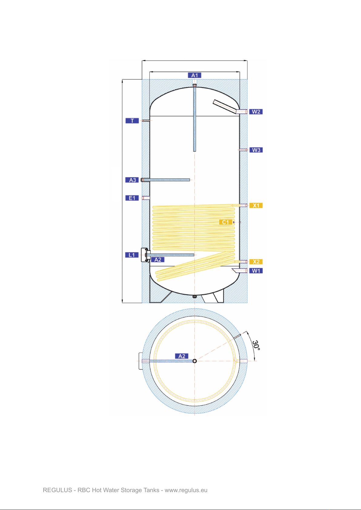
Connect the heat source to the inlets and outlets of X1 and X2 heat exchangers using G 5/4“ fittings.
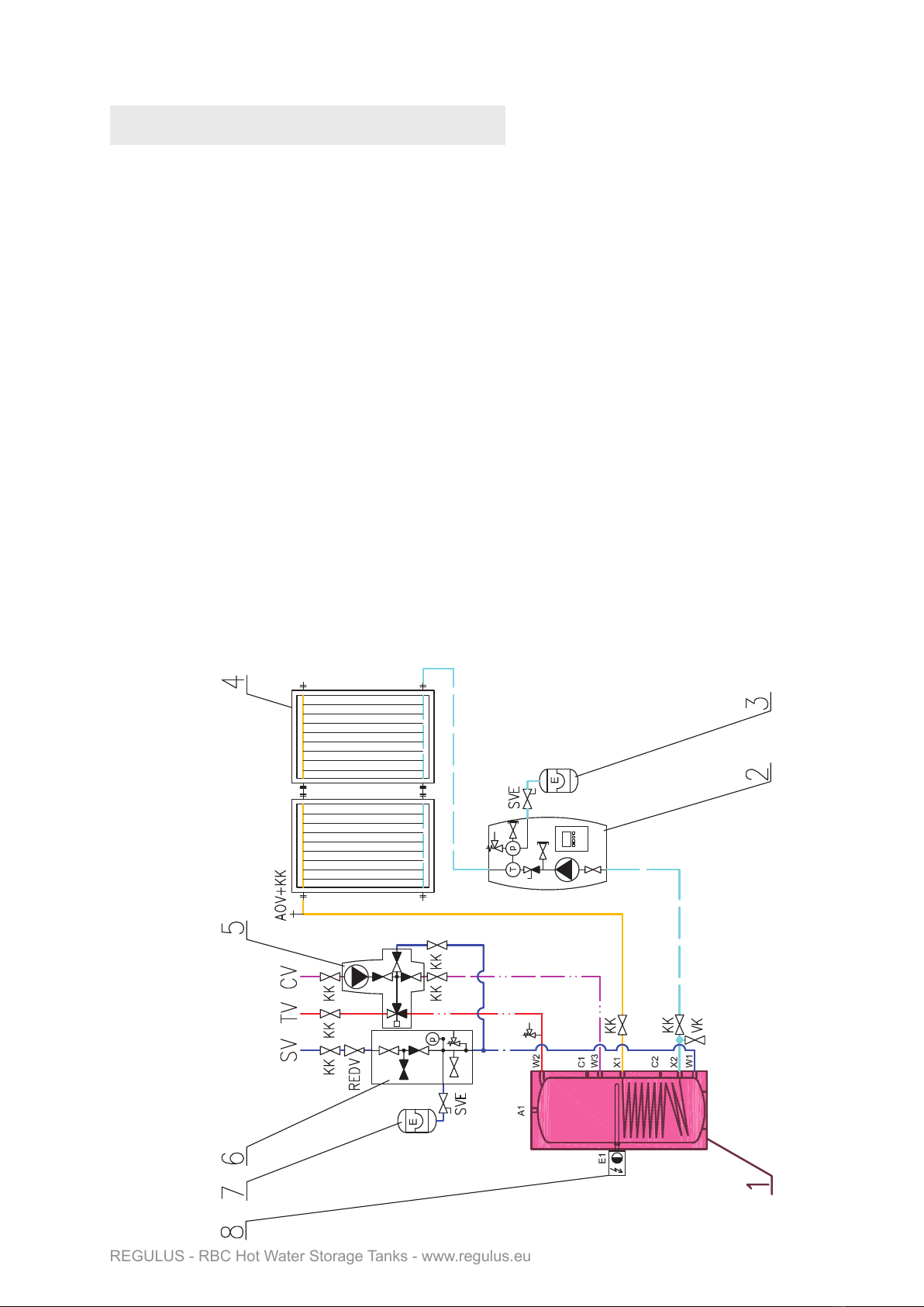
6.2 - Connection to a solar thermal system
This tank can also be used with a solar thermal system. In such a case, the inlet from a solar thermal system
connects to the upper G 5/4“sleeve of the heat exchanger marked X1, and the lower outlet X2 connects to the
return piping to the solar thermal system. Insulate all the piping between the tank and the solar thermal system
using insulation suitable for solar applications.
6.3 - Heating element installation
The G 6/4“ side connection marked E1 is designed to accommodate an electric heating element. Tanks of all
sizes can be retrofitted with another heating element installed in the L1 lower flange. The precondition for this is
replacing magnesium anode rods with an electronic one, and replacing the factory-supplied flange with a new
flange containing a G 6/4“ for the installatioon of an el. heatimg rod and a G 1/2“ connection for an electronic
anode rod. Codes of Electronic Anode Kits w. flanges needed for installation of another heating element can be
found in the table in Chap. 6.5. Heating elements of output up to 12 kW can be used (depending on the tank
diameter and element length), connected either directly to the mains (thermostat-equipped elements), or via a
heating system controller. The installation may be done by qualified staff only.
Warning: Electric heating elements shall be protected by a safety thermostat.
6.4 - Connection to water mains
DHW piping shall be done according to valid rules. Pipe fittings are used to connect the tank to a cold water inlet
and hot water outlet. Install a safety group that meets the requirements of ČSN 06 0830 - e.g. code 17387 or
18678 depending on the tank volume. Installation of a pressure reducing valve to the tank inlet is recommended.
If the pressure from water mains exceeds 6 bar, a pressure reducing valve is necessary. In order to prevent
water loss, an expansion vessel should be installed at the cold water inlet as well (8 l volume for RBC 200, 12 l
volume for RBC 300 and 400, 18 l volume for RBC 500, 24 l volume for RBC 750, 35 l volume for RBC 1000, 60
l volume for RBC 1500, 80 l volume for RBC 2000, 100 l volume for RBC 2500 and 2×60 l volume for RBC 3000).
Should the water be too hard, install a water softener before the tank. In case the water contains mechanical
impurities, install a filter.
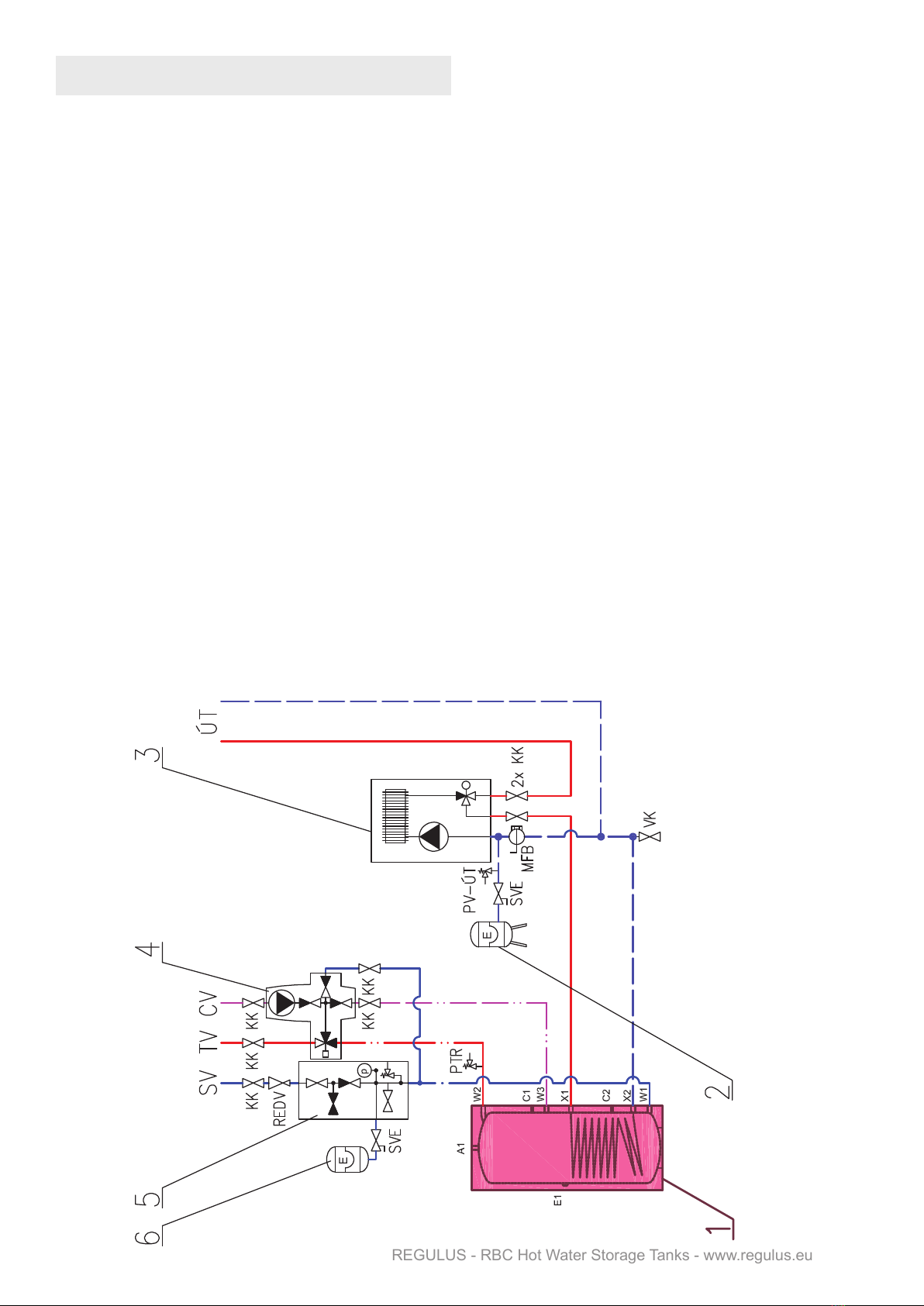
A pressure temperature relief valve (PTR) shall be installed at the hot-water outlet from the tank - e.g. code
17240 with a connection kit 17526. It is also recommended to install a corresponding anti-scald valve that
prevents too hot water from entering the taps.
Install a drain valve to the lowest point of the tank.
Complete DHW piping shall be properly insulated.
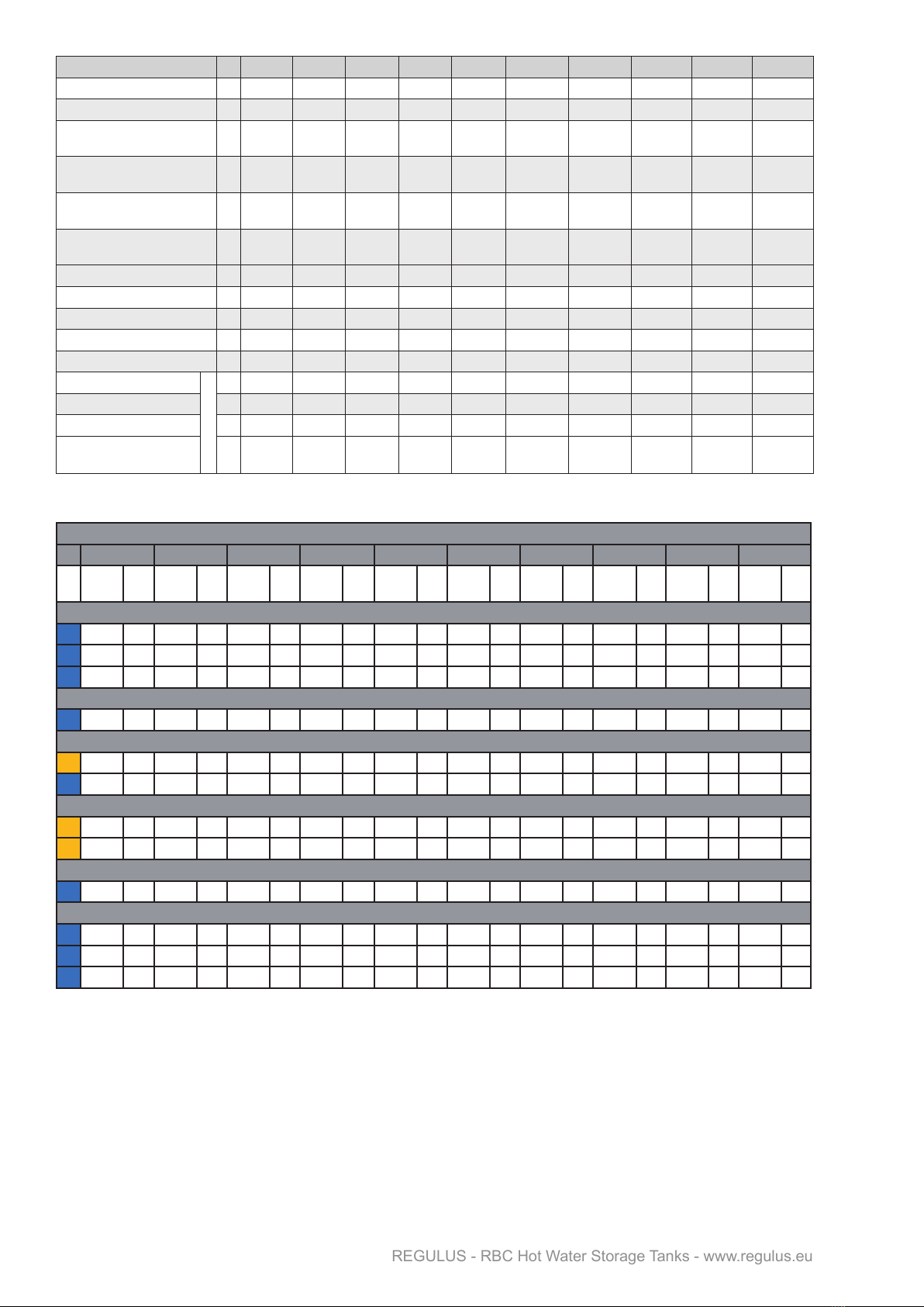
6.5 - Electronic anode rod installation
An electronic anode rod can be installed instead of the magnesium one. Its principle advantage is that it is
not necessary to dismantle it from the tank to determine its function. In such a case, just visual check of the
electronic anode rod is sufficient.
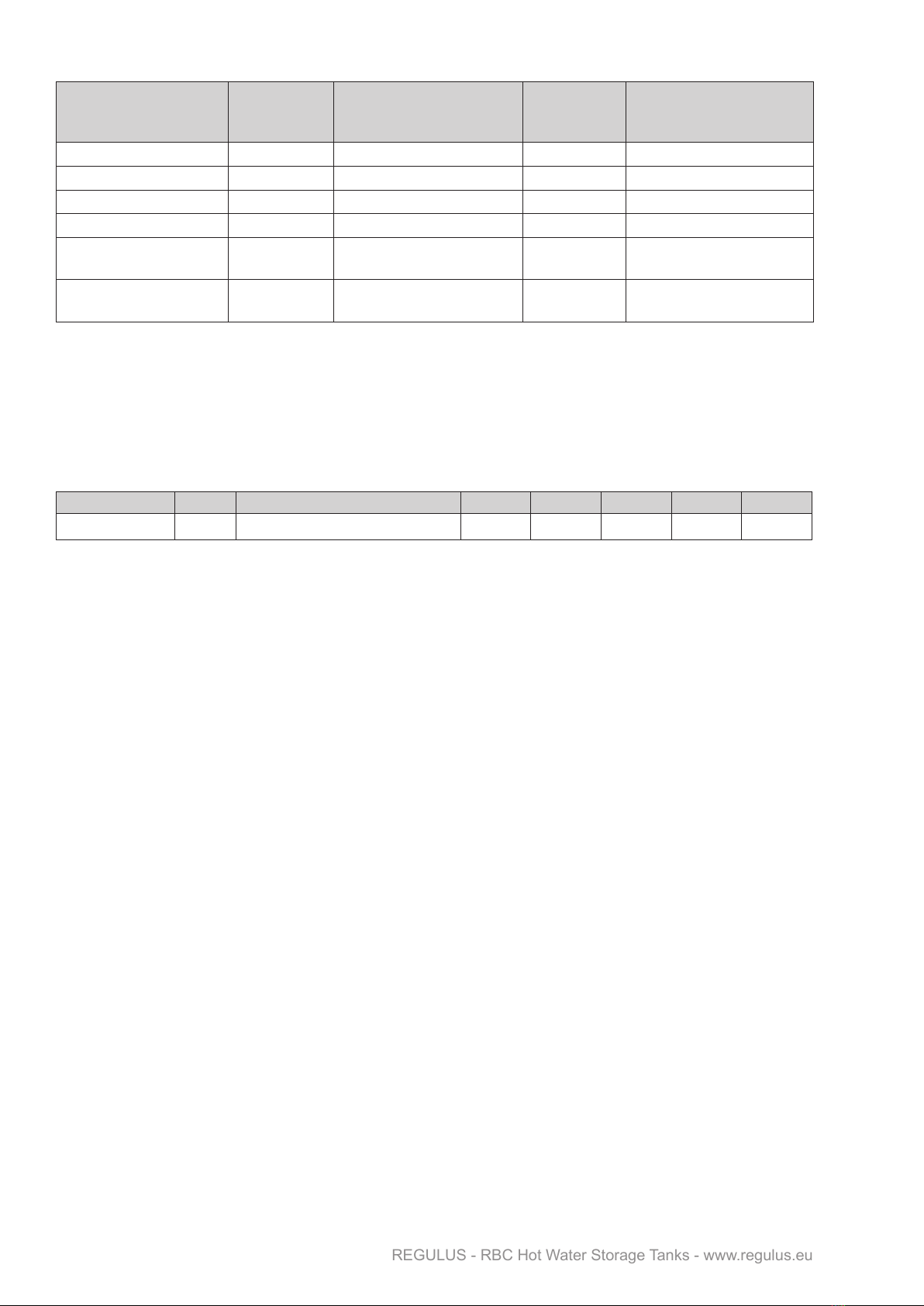
A space equal to the el. anode length is needed between the tank top and ceiling to install/replace the electronic
anode rod, see the table below. In order to protect the tank properly and meet its warranty conditions, select the
proper electronic anode rod from the table below.

│10
REGULUS - RBC Hot Water Storage Tanks - www.regulus.eu
Electronic Anode Kits for RBC Hot Water Storage Tanks
6.6 - Commissioning
Hot water quality must meet the conditions shown in the Table of limit values for total dissolved solids in
hot water.
Fill the heating circuits with the appropriate fluids and air-bleed the entire system. Check all connections for
leaks and verify the system pressure. Set the heating controller in compliance with the documentation and
manufacturer’s recommendations. Check regularly a proper function of all control and adjusting elements.
7 - Tank Insulation
Product description
Thermal insulation is a component of tanks that prevents heat losses. Thermal insulation of polyurethane foam
with zipped PVC layer is used.
Warning
Insulation dismantling and installation shall be done in two or three persons, depending on its size. The foam
insulation with zipper must not be dismantled/installed at temperatures below 20 °C. If this cannot be
avoided, the insulation shall be pre-warmed in another room to at least 20 °C. It is impossible to install insulation
of lower temperature, there is a risk of damage, esp. to the zipper.
Do not use any tools for installation.
Keep away from open fire.
Warranty on insulation
□ Warranty shall become null and void if:
○ the product was used for other purposes than intended.
□ Warranty does not cover:
○ usual wear and tear,
○ damage caused by fire, water, electricity or a natural disaster,
○ defects caused by failure to use the product in compliance with its intended purpose,
by improper use and insufficient maintenance,
○ defects caused by mechanical damage to the product,
○ defects caused by tampering or incompetent repair.
For tanks
El. Anode
Kit code -
replacement
Anode rod length
El. Anode
Kit code w.
lower ange*
Anode rod length
RBC 200 9173 350 (200/150) - -
RBC 300 9174 500 (350/150) - -
RBC 400, RBC 500 17368 500 (350/150) + 350 (200/150) 17432 500 (350/150) + 350 (200/150)
RBC 750, RBC 1000 17369 600 (350/250) + 450 (200/250) 17433 600 (350/250) + 450 (200/250)
RBC 1500, RBC 2000,
RBC 2500 14429 800 (550/250) + 600 (350/250) 17435 800 (550/250) + 600 (350/250)
RBC 3000 17371 800 (550/250) + 750 (550/200)
+ 800 (550/250) 17436 800 (550/250) + 750 (550/200)
+ 800 (550/250)
* The Kit shall be used when an electric heating element needs to be installed in the lower flange.
Table of limit values for total dissolved solids in hot water
Description pH Total dissolved solids (TDS) Ca Chlorides Mg Na Fe
Max. value 6.5 - 9.5 600 mg/l 40 mg/l 100 mg/l 20 mg/l 200 mg/l 0.2 mg/l

11 │
REGULUS - RBC Hot Water Storage Tanks - www.regulus.eu
8 - Maintenance, Replacement
of Magnesium Anode Rod
If the tank is fitted with a heating element, disconnect it from the mains first. Clean the exterior of the tank with
a soft cloth and a mild detergent. Never use abrasive cleaners or solvents
Check all connections for leaks. The tanks come equipped with an anti-corrosion sacrifice magnesium anode
rod as standard; it protects its inner parts against corrosion. The anode rod shall be checked within 12 months
after commissioning and subsequently always not later than 12 months after the last check. In locations where
water contains more ferrites or calcites, it is recommended to check the anode every 6 months. If more than 1/3
of its total volume is consumed, the anode shall be replaced with a new one. Disregarded of its state, the anode
rod shall be replaced with a new one within 24 months from commissioning. In case an electronic anode is used,
the above described procedures are not necessary. Then only a visual check of the indication lamp is necessary
every 3 months. Indication of the proper working of the electronic anode rod is described in its Installation and
Operation Manual.
If damage to a tank occurs due to neglected substitution of a magnesium anode rod or a non-working electronic
anode, the warranty cannot be claimed.
9 - Disposal
Packing shall be disposed of in compliance with the valid rules. When the product reaches the end of its life,
it shall not be disposed of as household waste. It shall be dropped off at a Local Waste Recycling Center.
Insulation shall be recycled as plastic and the steel vessel as scrap iron.
10 - Warranty
This product is covered by warranty according to the conditions described in this Manual and according to
the Warranty Certificate. A Warranty Certificate is an integral part of the supply. Tank transport or storing in
a horizontal position is considered a warranty violation!

REGULUS spol. s r.o.
E-mail: [email protected]
Web: www.regulus.eu
v2.0-05/2022
©2022 We reserve the right to errors, changes and improvements without prior notice.
This manual suits for next models
19
Table of contents
Other Regulus Tank Equipment manuals
Popular Tank Equipment manuals by other brands

Garnet
Garnet SeeLeveL II 709 Series Installation guide & user manual

TransTank
TransTank DieselPatrol Operator's handbook

Thomas
Thomas 7184 user guide

Genesis
Genesis KOCKON VX Series Installation

ENCON
ENCON SAF-T-TUB 01052539 Installation, operation and maintenance manual

Gardena
Gardena 4000/5 eco operating instructions