TriCom TCR-MBA-75 User manual

TRICOM RESEARCH, INC.
OPERATOR'S MANUAL
TCR-MBA-75
REMOTE MULT-IBAND AMPLIFIER
DOCUMENT # 90400-01050
Tricom Research, Inc. •http://www.tricomresearch.com
17981 Sky Park Circle, Suite M, Irvine, CA 92614
(949) 250-6024 ph •(949) 250-6023 fax

TCR-MBA-75 OPERATOR’S MANUAL
i
TABLE OF CONTENTS
1.0 INTRODUCTION
1.1 General Information.......................................................................................1-1
1.2 Abbreviations and Glossary...........................................................................1-2
1.3 Equipment Description ..................................................................................1-3
1.4 Features..........................................................................................................1-3
1.5 TCR-MBA-75 System ...................................................................................1-5
1.5.1 Amplifier........................................................................................................1-5
1.5.2 Bias Tee II......................................................................................................1-5
1.5.3 Power Cable ...................................................................................................1-5
1.6 Specifications.................................................................................................1-7
2.0 OPERATION
2.1 General Information.......................................................................................2-1
2.2 Controls, Indicators, and Connectors.............................................................2-1
2.3 Operational Procedures..................................................................................2-3
2.3.1 General Information.......................................................................................2-3
2.3.2 Equipment Set-up...........................................................................................2-3
2.3.3 Operating Procedures.....................................................................................2-4
2.3.3.1 Normal Operation ..........................................................................................2-4
2.3.3.2 MBITR Specific Operation............................................................................2-4
2.3.3.3 Bypass Operation...........................................................................................2-4
2.3.3.5 Improper Operation........................................................................................2-5
3.0 INSTALLATION
3.1 General Information.......................................................................................3-1
3.2 Preparation for Use ........................................................................................3-1
3.3 Cable Interconnections...................................................................................3-1
3.4 Software Installation ......................................................................................3-1
Revision History - Document 90400-01050
Revision Description Date
Rev A
Initial Release
15 may 2009

TCR-MBA-75 OPERATOR’S MANUAL
ii
LIST OF TABLES
Table 1-1 TCR-MBA-75 General Operating Parameters.........................................1-7
Table 1-2 TCR-MBA-75 Interconnect Characteristics ............................................1-9
Table 2-1 TCR-MBA-75 Controls, Indicators, and Connectors ..............................2-2
Table 2-2 BIAS TEE II Controls, Indicators, and Connectors.................................2-3
Table 2-3 TCR-MBA-75 System Troubleshooting Guide .......................................2-5
LIST OF FIGURES
Figure 1-1 TCR-MBA-75 System Components ........................................................1-1
Figure 1-2 TCR-MBA-75 Functional Block Diagram ..............................................1-6
Figure 2-1 TCR-MBA-75 Controls, Indicators, and Connectors ..............................2-1
Figure 2-2 BIAS TEE II Controls, Indicators, and Connectors.................................2-2
Note: The information contained herein is for reference only and does not constitute a
warranty of performance.
TCR-MBA-75 OPERATOR’S MANUAL
1-1
1.0 INTRODUCTION
1.1 GENERAL INFORMATION
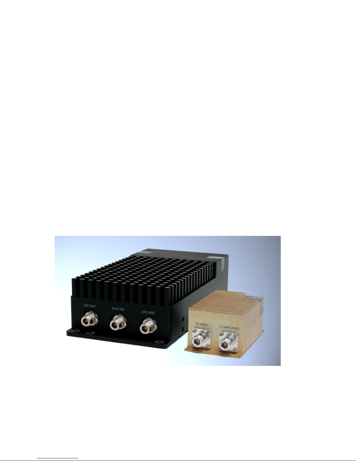
This manual provides operating instructions for the DAMA certified TCR-MBA-
75 Remote Amplifier Multiband Platform shown in Figure 1-1. The TCR-MBA-
75 is designed as a form and fit replacement for the AM-SAT-50 UHF SATCOM
Amplifier with enhanced functionality. The footprint and mounting provisions
for the AM-SAT-50 and TCR-MBA-75 are identical. The Bias Tee and Bias Tee
II have identical footprints and mounting, but the Bias Tee II has a slightly higher
profile to house the added remote control circuitry required for the TCR-MBA-75.
The TCR-MBA-75 is an amplifier/pre-amplifier designed to provide transmit and
receive gain for:
•Multiband line of sight (LOS) 30~512 MHz communications;
•SINCGARS frequency hopping 30~88 MHz operation; and,
•UHF Tactical SATCOM (242~268 MHz receive and 292~318 MHz
transmit) frequencies with cosite supression.
The TCR-MBA-75 is DAMA Certified with several UHF SATCOM terminals.
For a listing of the current certifications please see the Joint Interoperability Test
Command (JITC) website.
Figure 1-1. TCR-MBA-75 System Components

TCR-MBA-75 OPERATOR’S MANUAL
1-2
1.2 ABBREVIATIONS AND GLOSSARY
AGC Automatic gain control
ALC Automatic level control
AM Amplitude modulation
ANT Antenna
BPS Bits per second
CT Cipher text
CW Continuous wave
COMSEC Communications security
dB Decibel
dBm Decibel referenced to 1 milliwatt (0 dBm = 1 mW)
FM Frequency modulation
Hz Hertz
KHz Kilohertz
LED Light emitting diode
LOS Line of sight
MHz Megahertz
mW Milliwatt
PT Plain text
PTT Push to talk
RCV Receive
SATCOM Satellite communications
UHF Ultra-high frequency
VDC Volts, direct current
VSWR Voltage standing wave ratio
W Watt
X-MODE Connector for COMSEC equipment
XMT Transmit

TCR-MBA-75 OPERATOR’S MANUAL
1-3
1.3 EQUIPMENT DESCRIPTION
The TCR-MBA-75 Remote Amplifier Multiband Platform provides transmit and
receive amplification for the 30 MHz to 512 MHz Line-of Sight (LOS), 30 MHz to 88
MHz SINCGARS Frequency Hopping, and the UHF Tactical SATCOM bands. It is
suitable for man-pack, vehicular, airborne, or fixed-station applications and is compatible
with most military and commercial radios. The Amplifier is weather-resistant and may
be located outdoors with the antenna. The Bias Tee II is splashproof and is normally
located with the radio but may be placed anywhere between the radio and amplifier. The
Bias Tee II controls the operation of the amplifier via front panel switches and may be
connected to a PC serial port for remote control with the TCR-MBA-75 windows
application. The amplifier has a single connection to the Bias Tee II and two frequency
specific antenna ports. The LOS port is for frequency hopping and multiband operation
anywhere between 30 and 512 MHz. The SATCOM port is used with UHF SATCOM
antennas. The Bias Tee II connection to the amplifier carries the control signals for the
amplifier as well as the RF communications signal. The Bias Tee II provides for
selection of LOS, SATCOM, Frequency Hopping or Amplifier Bypass Modes, allows the
LNA to be enabled or disabled and also provides the amplifier output power selection.
Some equipment that is compatible with the TCR-MBA-75 includes:
•Directional and broadband antennas with a 50 Ohm impedance
•LOS, multiband and SATCOM radios, including the MBITR, the
AN/PSC-5, the AN/PRC-117, and the SINCGARS terminals.
•Conditioned power from a 28 VDC source.
1.4 FEATURES
The TCR-MBA-75 has the following features:
•JITC DAMA Compatible
•Coverage from 30 to 512 MHz, including SINCGARS Frequency
Hopping compatibility
•Connections for both a SATCOM and an LOS antenna
•Bias Tee II and PC remote control of amplifier functions
•Pre-amplification of received RF signals from antennas
•Power amplification of transmit signals to 35, 50 or 75 Watts

TCR-MBA-75 OPERATOR’S MANUAL
1-4
•Transmit and receive band filtering to supress interference from
co-located radios and amplifiers in SATCOM mode
•Bias Tee II and Amplifier front panel indication of system status

TCR-MBA-75 OPERATOR’S MANUAL
1-5
1.5 TCR-MBA-75 SYSTEM
The TCR-MBA-75 is pictured in Figure 1-1.
1.5.1 Amplifier
The Amplifier consists of several printed circuit assemblies, a filtering and
switching network, and RF connectors housed in a water resistant aluminum housing.
With normal care and maintenance, the assembly is highly resistant to corrosion from the
elements. The RF connections to the Bias Tee II and to the SATCOM and LOS antennas
are Female Type N. Power to operate the amplifier is sent over the RF cable connected
to the BIAS Tee II. There is no provision to power the amplifier on the amplifier housing
and operation without a Bias Tee II is not possible. The amplifier will not interoperate
with the bias tee used with the AM-SAT-50.
1.5.2 Bias Tee II
The Bias Tee II consists of several printed circuit assemblies and associated
connectors and switches housed in a water resistant aluminum housing. With normal
care and maintenance, the assembly is highly resistant to corrosion from the elements.
The Bias Tee II has three switches controlling: 1) Transmit power level, 2) LNA active,
LNA bypass and system bypass, and 3) SATCOM, LOS and Frequency Hopping
operation. Type N connections are provided for the radio and amplifier signals. A
female 9 pin D-subminiature connection is provided for optional remove control
operation from the serial port of a PC. The Bias Tee II will auto detect the connection to
a PC serial port and configure itself for remote control operation.
1.5.3 Power Cable
A multi-conductor cable connects the Bias Tee II with a 28 VDC power source.
A wiring diagram for the cable is shown in Section 3 of this manual. The cable is
identical to the power cable used for the AM-SAT-50 and AM-SAT-100 amplifiers.

TCR-MBA-75 OPERATOR’S MANUAL
1-6
1.6 Specifications
The operating parameters, physical characteristics, and environmental specifications are
shown in the following tables.
Table 1-1. TCR-MBA-75 Nominal Performance Specifications
TRANSMIT SECTION
SATCOM OPERATION
Frequency Range 292-318 MHz
Input Power 5 Watts typical (2-18 Watts)
Output Power 35/50/75 Watts
Switching Speed DAMA Certified
Modulation FM or multiphase, 5 or 25 KHz bandwidth
Filtering Cosite supression
Harmonics -60 dBc
LOS OPERATION
Frequency Range 30-512 MHz
Band Selection Fully automatic
Input Power 5 Watts typical (2-18 Watts)
Output Power 50 Watts
Modulation AM, FM or multiphase, 5 or 25 KHz bandwidth
Harmonics -60 dBc
FREQ HOP OPERATION
Frequency Range 30~88 MHz
Band Selection Fully automatic
Input Power 5 Watts typical (2-18 Watts)
Output Power 50 Watts
Modulation SINCGARS FM
Harmonics -60 dBc
General
Transmit Duty Cycle 100 % with sufficient natural convection
RECEIVE SECTION
SATCOM OPERATION
Frequency Range 242-268 MHz
Noise Figure 3.5 dB
Receive Gain 10 dB (or bypass LNA)
Filtering Cosite Supression

TCR-MBA-75 OPERATOR’S MANUAL
1-7
LOS OPERATION
Frequency Range 30-512 MHz
Insertion Loss 1.5 dB
ADDITIONAL SPECIFICATIONS
Input/Output VSWR 2.0:1
RF Connections Type N female
Protection VSWR, temperature
Indicators DC ON, LOS, SATCOM, XMT,
COMM FAULT, HI VSWR, HI TEMP
DC Power 28 VDC, 12 A XMT, 500 mA RCV
Operating Temperature -20 to +60 C
Bypass Operation Routes Radio signal to LOS port
Environmental IP-67
Dimensions 6 x 3 x 12 inches
Same as AM-SAT-50
Weight 10 lbs
BIAS TEE II SPECIFICATIONS
Input/Output VSWR 2.0:1
RF Connections Type N female
Protection Short circuit
Indicators RS-232 FAULT, COMM FAULT,
HI VSWR, HI TEMP, DC ON, XMT
Controls Power: 35/50/75 Watts
Bypass: LNA on, LNA bypass,
amplifier bypass
Mode: SATCOM, LOS, Freq Hopping
Operating Temperature -20 to +60 C
Remote Operation RS-232 serial PC communications
Environmental IP-67
Dimensions 3 x 5 x 2 inches
1/2 inch taller than standard Bias Tee
Weight 1 lbs

TCR-MBA-75 OPERATOR’S MANUAL
1-8
Table 1-2. TCR-MBA-75 Interconnect Characteristics
Connection
Signal/Pin
Connector Function
AMPLIFIER
BIAS TEE
RF and control to Bias Tee II
Type N female
SATCOM
RF to SATCOM antenna
Type N female
LOS
RF to LOS antenna
Type N female
Bias Tee II
DC IN
DC power input
PIN A
PIN B
PIN C
PIN D
PIN E
MS3102E-14S-5P on BIAS
TEE II
(mating connector for cable use
is MS3106F-14S-5S)
+28 VDC Input
+28 VDC Input
GND
GND
+28 VDC Input
RADIO
RF to radio
Type N female
AMPLIFIER
RF to amplifier
Type N female
COMM PORT
Remote control from PC serial port
1
2
3
4
5
6
7
8
9
D sub 9 position female
N/C
TXD
RXD
N/C
GND
N/C
CTS
RTS
N/C
TCR-MBA-75 OPERATOR’S MANUAL
2-1
2.0 OPERATION
2.1 General Information
This section provides information for operating the TCR-MBA-75.
WARNING
Electromagnetic radiation from the antenna can damage eyes and other body tissue
when the system is transmitting. DO NOT stand directly in front of the antenna or
in close proximity to the sides or back of the antenna when transmitting.
2.2 Controls, Indicators, and Connectors
The TCR-MBA-75’s BIAS TEE II has toggle switches to control:
•Transmit power selection (35, 50 or 75 Watts)
•Operational mode (LNA on, LNA bypass, or remote control)
•Frequency band (SATCOM, LOS or Amplifier bypass)
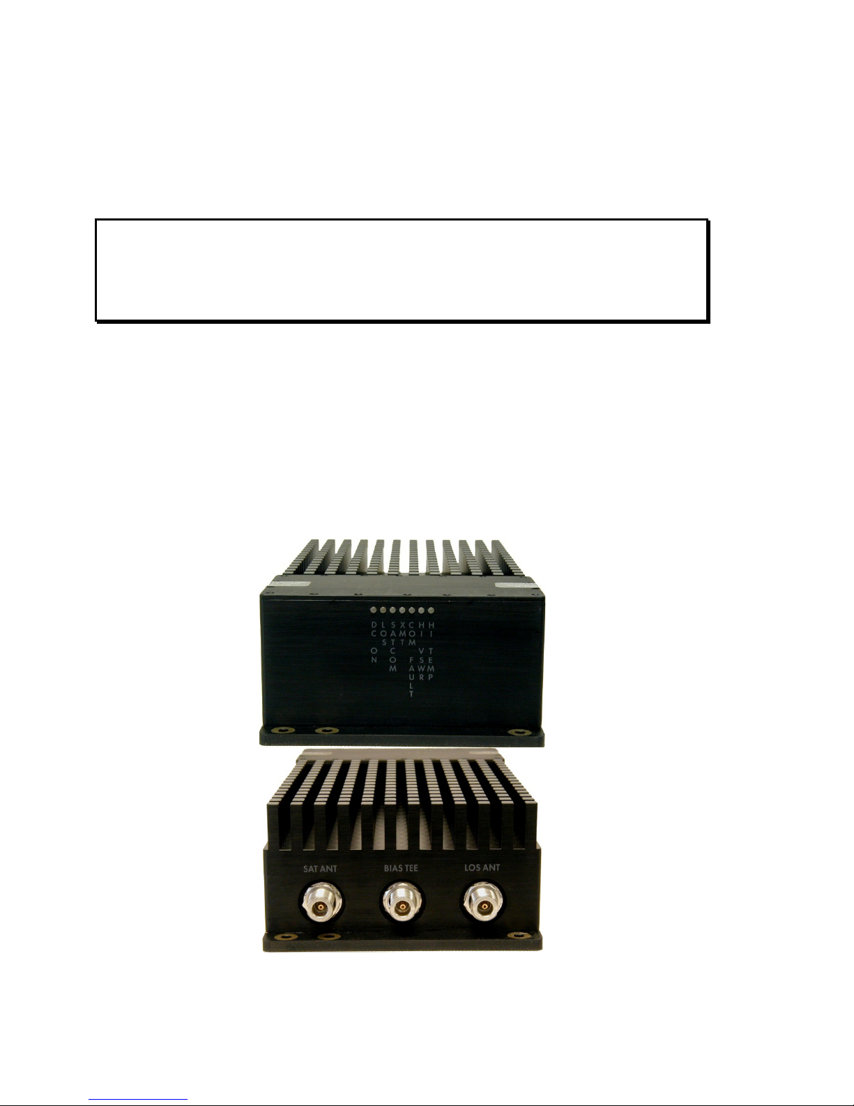
There are also several status indicators on the Amplifier's front panel as shown in Figures
2-1 and 2-2. The functions of these are specified in Tables 2-1 and 2-2.
Figure 2-1. TCR-MBA-75 Controls, Indicators, and Connectors

TCR-MBA-75 OPERATOR’S MANUAL
2-2
Table 2-1. TCR-MBA-75 Controls, Indicators, and Connectors
CONTROL, INDICATOR,
CONNECTOR
TYPE
FUNCTION
DC On
LED
Indicates that DC power is supplied to the
amplifier
LOS
LED
Indicates the Line of Sight connection has been
enabled
SATCOM
LED
Indicates the SATCOM connection has been
enabled
XMT
LED
Indicates that the amplifier is in the transmit
mode
COMM Fault
LED
Indicates a communications fault between the
amplifier and Bias Tee II
HI VSWR
LED
Indicates that the amplifier has sensed a high
VSWR condition
HI Temp
Indicates that the amplifier has sensed a high
temperature condition
SAT ANT
TYPE N
Connect to SATCOM antenna
BIAS TEE
TYPE N
Connect to the BIAS TEE II
LOS ANT
TYPE N
Connect to Line of sight antenna
Figure 2-2. BIAS TEE II Controls, Indicators, and Connectors

TCR-MBA-75 OPERATOR’S MANUAL
2-3
Table 2-2. BIAS TEE II Controls, Indicators, and Connectors
CONTROL, INDICATOR,
CONNECTOR
TYPE
FUNCTION
RS-232 Fault
LED
Indicates a problem with the RS-232 interface
when illuminated
Comm Fault
LED
Indicates a communications fault between the
amplifier and Bias Tee II
Hi VSWR
LED
Indicates a high VSWR condition on the
selected antenna port
Hi Temp
LED
Indicates a high temperature condition
DC On
LED
Indicates DC power to the Bias Tee II
XMT
LED
Indicates that the amplifier is in the transmit
mode
To Radio
TYPE N
Connect to SATCOM/LOS/Multiband radio
To Amplifier
TYPE N
Connect to the TCR-MBA-75 Amplifier
DC Power
MS3102E-14S-5P
Connect to 28 VDC power source
Comm Port
9 pos d-sub female
Connect to PC serial port (optional)
TX Power
3 position toggle
35, 50, 75 W SATCOM (50 W LOS only)
Mode
3 position toggle
LNA On, LNA Bypass, AMP Bypass
Antenna
3 position toggle
SATCOM, LOS, Frequency Hopping
2.3 Operational Procedures
2.3.1 General Information
The TCR-MBA-75 can be used for operation once it has been installed as
described in Section 3.
2.3.2 Equipment Set-up
Refer to Paragraph 2.2 for the locations and functional description of the controls
and indicators. Make sure that the TCR-MBA-75 has been installed according to the
instructions provided in Section 3.

TCR-MBA-75 OPERATOR’S MANUAL
2-4
2.3.3 Operating Procedures
2.3.3.1 Normal Operation
In operation, the TCR-MBA-75 provides receive gain and transmit power
amplification for radios operating in the UHF SATCOM band when the SATCOM
connector is selected using the SAT/LOS/BYPASS switch and the LNA option is
selected with the Mode switch. It provides a low loss RF path with no gain and transmit
power amplification for radios operating anywhere in the 30-512 MHz band when the
LOS connector is selected using the SAT/LOS/BYPASS switch.
Operating outside of the UHF SATCOM frequency bands with the SATCOM mode
selected will cause an alarm to occur. The equipment will not transmit correctly until the
amplifier power switch has been cycled off.
Operating on SATCOM frequencies while in the LOS mode with an antenna connected
to the LOS port will not cause an alarm and it will operate properly, however, the
amplifier will not comply with the timing requirements for DAMA operation.
The transmit power switch selects the power level for SATCOM operation. The default
transmit power for LOS operation is 50 Watts and is not controlled by the transmit power
switch.
The Mode switch selects the LNA On or Off condition for SATCOM operation. In LOS
operation the LNA is automatically disabled.
The antenna select switch provides selection for either the SATCOM or LOS antenna
connector. When the AMP BYPASS is selected the amplifier is powered off and the
BIAS TEE port is internally routed to the LOS port on the amplifier. If DC power is
removed from the Bias Tee II the BIAS TEE port is internally routed to the LOS port on
the amplifier.
2.3.3.2 MBITR Specific Operation
There may be an interoperability issue when operating the MBITR radio with
amplifiers that have a receive low noise amplifier (LNA). Using the LNA ON setting
with the MBITR may prevent the radio from operating properly
2.3.3.3 Bypass Operation
When DC power is removed or when the AMP Bypass position is selected the
radio port is directly connected to the LOS antenna port.

TCR-MBA-75 OPERATOR’S MANUAL
2-5
2.3.3.4 Improper Operation
If the communications system seems to be operating improperly, check to make
sure that the equipment is configured in accordance with Section 3. If the problem
persists follow the instructions below.
Table 2-2. TCR-MBA-75 System Troubleshooting Guide
SYMPTOM
PROBABLE CAUSE
SUGGESTED FIX
XMT light flashes
when transmitting
High Temp Light
COMM fault
Hi VSWR
Low output power
Incorrect operating
frequency for selected
mode
Excessive heat build-up
Bad connection from
Bias-Tee to Amplifier
Antenna problem or bad
cable
Low input voltage or
drive level
Change mode or frequency for
proper operation
Decrease duty cycle or provide
increased ventilation
Check cables, cycle DC power
Check antenna spec and cable
Check DC voltage while
transmitting and radio output
power setting

3.0 INSTALLATION
3.1 General Information
This section contains information necessary for preparing the TCR-MBA-75 for
use.
3.2 Preparation for Use
After unpacking the system and inspecting for physical damage, select an
appropriate location for the Amplifier. Although the Amplifier is weather-resistant,
placing it in a location where it is protected from direct salt spray, rain, and sunlight will
to increase its service life. Make sure that adequate air flow is available to keep the heat
sink of the amplifier cool.
3.3 Cable Interconnections
Attach the DC power source to the DC IN connector. Attach one or two antennas
to the antenna ports. Select the antenna and operating mode with the selector switches.
3.4 Software Installation
Remote control of the TCR-MBA-75 amplifier can be accomplished using a PC serial
port with the TCR-MBA-75 GUI installed. Run the setup file and follow the on-screen
prompts. When the Bias Tee is connected to an active serial port and the remote control
software will override the switches on the front panel of the Bias Tee.
Other manuals for TCR-MBA-75
1
Table of contents
Other TriCom Amplifier manuals


