TriCom TCR-MBA-75 User manual
OPERATOR'S MANUAL
TCR-MBA-75 NBT
MULTI-BAND RF AMPLIFIER
DAMA CERTIFIED
DOCUMENT # 90400-01076 REV D
Tricom Research, Inc. http://www.tricomresearch.com
17791 Sky Park Circle, Suite J, Irvine, CA 92614
Ph: (949) 250-6024 fax: (949) 250-6023

TCR-MBA-75 NBT OPERATOR’S MANUAL
i
TABLE OF CONTENTS
1.0 INTRODUCTION
1.1 General Information .......................................................................................1
1.2 Abbreviations and Glossary ...........................................................................2
1.3 Equipment Description ..................................................................................3
1.4 Features ..........................................................................................................3
1.5 TCR-MBA-75 NBT System ..........................................................................4
1.5.1 Amplifier Components...................................................................................4
1.5.2 Power Cable ...................................................................................................4
1.6 Specifications .................................................................................................4
2.0 OPERATION
2.1 General Information .......................................................................................6
2.2 Controls, Indicators, and Connectors .............................................................7
2.3 Operational Procedures ..................................................................................8
2.3.1 General Information .......................................................................................8
2.3.2 Equipment Set-up...........................................................................................8
2.3.3 Operating Procedures .....................................................................................8
2.3.3.1 Normal Operation ..........................................................................................8
2.3.3.2 MBITR Specific Operation ............................................................................9
2.3.3.3 Remote Operation…………………………………………………………...10
2.3.3.4 Out of Band Operation…………………………………………………... ....11
2.3.3.5 Bypass Operation ...........................................................................................11
2.3.3.6 Troubleshooting .............................................................................................11
2.3.3.7 Collocation……………………………………………. ................................11
3.0 INSTALLATION
3.1 General Information .......................................................................................12
3.2 Preparation for Use ........................................................................................12
3.3 Cable Interconnections ...................................................................................12

TCR-MBA-75 NBT OPERATOR’S MANUAL
ii
LIST OF TABLES
Table 1-1 TCR-MBA-75 General Operating Parameters .........................................4
Table 1-2 TCR-MBA-75 Interconnect Characteristics ............................................6
Table 2-1 TCR-MBA-75 Controls, Indicators, and Connectors ..............................8
Table 2-2 TCR-MBA-75 System Troubleshooting Guide………. ..........................12
Table 3-1 DC Input Power connector pin out…………………………………......13
LIST OF FIGURES
Figure 1-1 TCR-MBA-75 NBT System Components ...............................................1
Figure 2-1 TCR-MBA-75 NBT Controls and Indicators ..........................................7
Figure 2-2 TCR-MBA-75 NBT Connectors ..............................................................7
Figure 2-3 Mode, Power and LNA Flow Chart…………………………………… .9
Figure 2-4 Bias Tee I For Remote Operation………………………………………10
Figure 2-5 Remote Operation Setup…………………………………………….….11
Figure 3-1 TCR-MBA-75 NBT DC Input Connector pin location...……………… 13
Figure 3-2 Amplifier Mounting Dimensions……………………....……………… .14
Note: The information contained herein is for reference only and does not constitute a
warranty of performance.

TCR-MBA-75 NBT OPERATOR’S MANUAL
iii
Revision History - Document 90400-01076
Revision Description Date
Rev A Initial Release 22 JUNE 2010
Rev B Added Fi
g
ure 3-2 Amplifier Mountin
g
Dimensions 29 MAY 2013
Rev C Reconcile technical data and data sheets 02 APR 2018
Rev D Revise 2.3.3.3 Remote Operatio
n
31 OCT 2018
1 | Page
1.0 INTRODUCTION
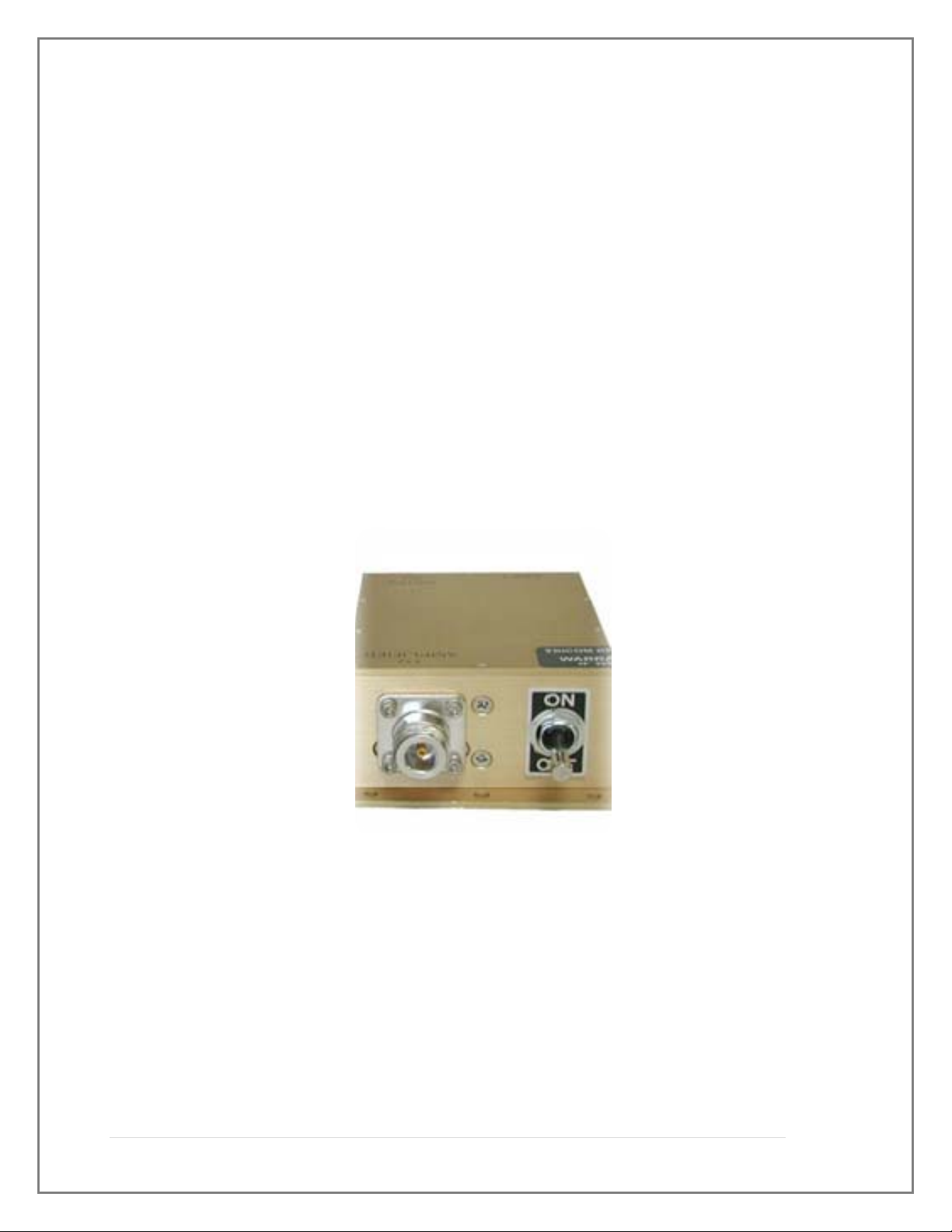
1.1 GENERAL INFORMATION
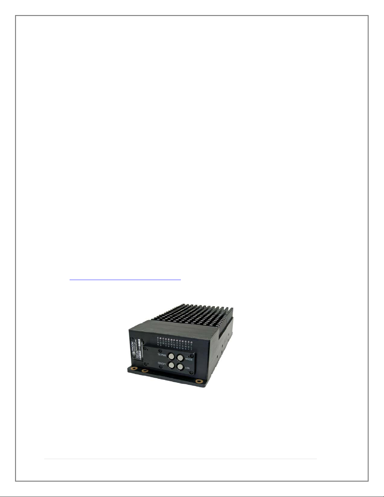
This manual provides operating instructions for the DAMA certified TCR-MBA-
75 NBT Multiband Amplifier shown in Figure 1-1. The designation NBT (non-
bias tee) simply indicates the ability to use the amplifier without the need for a
bias tee by using the front panel DC connector. The TCR-MBA-75 NBT is
designed as a form and fit replacement for the AM-SAT-50 UHF SATCOM or
TCR-MBA-75 Amplifier with enhanced functionality. The footprint and
mounting provisions for the AM-SAT-50, TCR-MBA-75 and TCR-MBT-75 NBT
are identical. The TCR-MBA-75 NBT is an amplifier/pre-amplifier designed to
provide transmit and receive gain for:
Multiband line of sight (LOS) 30~512 MHz communications;
HAVEQUICK 225-400 MHz and SINCGARS frequency hopping 30~88
MHz operation; and,
UHF Tactical SATCOM (242~268 MHz receive and 292~318 MHz
transmit) frequencies with Low Noise Amplifier (LNA) and Cosite
suppression.
Part number: 11000-00678
The TCR-MBA-75 NBT is DAMA Certified with several UHF SATCOM
terminals. For a listing of the current certifications please see the Joint
Interoperability Test Command (JITC) Website:
http://jitc.fhu.disa.mil/reg/dama.html
Figure 1-1. TCR-MBA-75 NBT Amplifier

2 | Page
1.2 ABBREVIATIONS AND GLOSSARY
AGC Automatic gain control
ALC Automatic level control
AM Amplitude modulation
ANT Antenna
BPS Bits per second
CT Cipher text
CW Continuous wave
COMSEC Communications security
dB Decibel
dBm Decibel referenced to 1 milliwatt (0 dBm = 1 mW)
FM Frequency modulation
Hz Hertz
IW Integrated Waveform
JITC Joint Interoperability Test Center (DISA)
KHz Kilohertz
LED Light emitting diode
LNA Low Noise Amplifier
LOS Line of sight
MHz Megahertz
mW Milliwatt
PT Plain text
PTT Push to Talk
RCV Receive
SATCOM Satellite Communications
UHF Ultra-high frequency
VDC Volts, direct current
VSWR Voltage standing wave ratio
W Watt
X-MODE Connector for COMSEC equipment
XMT Transmit

3 | Page
1.3 EQUIPMENT DESCRIPTION
The TCR-MBA-75 NBT Multi-band RF Amplifier operates in 30 MHz to 512
MHz AM and FM Line-of Sight (LOS), 30 MHz to 88 MHz SINCGARS Frequency
Hopping, 225 MHz to 400 MHz HAVEQUICK, and UHF Tactical SATCOM modes. It
is suitable for vehicular, airborne, or fixed-station applications and is compatible with
most military and commercial radios operating in the 30-512Mhz frequency spectrum.
The amplifier is weather-resistant and may be located outdoors with the antenna via Bias
Tee I (for information on this see Para. 2.3.3.1 Normal Operations). The operation of the
amplifier is controlled via front panel push button switches. The amplifier has a single
power connection, an RF input port and two frequency specific output antenna ports. The
LOS port is for frequency hopping and multiband Line of Site operation anywhere
between 30 and 512 MHz. The SATCOM port is used with UHF SATCOM antennas in
the 292-318 MHz uplink and 242-268 MHz downlink bands. The Mode push button
switch provides for selection of LOS AM or FM, SATCOM, Frequency Hopping
(SINCGARS), and Frequency Hopping AM (Have Quick). The LNA push button switch
allows the LNA to be enabled or disabled in SATCOM. The TX power push button
switch provides the amplifier output power selection in SATCOM mode. Some
equipment that is compatible with the TCR-MBA-75 NBT includes but is not limited to:
LOS, multiband and SATCOM radios, including the AN/PRC-148 JEM and
MBITR, the AN/PSC-5 series, AN/PRC-117F, AN/PRC-117G AN/PRC-152
Falcon III Handheld, and the AN/PRC-119 SINCGARS terminals.
Directional and broadband antennas with 50 Ohm impedance
Conditioned power from a 28 VDC nominal source.
1.4 FEATURES
The TCR-MBA-75 NBT has the following features:
JITC DAMA Certified
Coverage from 30 to 512 MHz, including SINCGARS FM and HAVEQUICK
AM Frequency Hopping compatibility
IW Compatibility
Connections for both a SATCOM and an LOS antenna
Pre-amplification of received RF signals from antennas in SATCOM mode
Power amplification of transmit signals to 35, 50 or 75 Watts in SATCOM
mode

4 | Page
Transmit and receive band filtering to suppress interference from
co-located radios and amplifiers in SATCOM mode
Amplifier front panel indication of system status
1.5 TCR-MBA-75 NBT SYSTEM
The TCR-MBA-75 NBT is pictured in Figure 1-1.
1.5.1 Amplifier Components
The Amplifier consists of several printed circuit assemblies, a filtering and
switching network, and RF connectors housed in an environmentally sealed aluminum
housing. With normal care and maintenance, the assembly is highly resistant to corrosion
from the elements. The RF connections to the RF input, SATCOM and LOS antennas
are Female Type N. Power to operate the amplifier is applied via a cable connected to
the 5 pin circular Mil DC input connector. A 3ft Power cable is supplied with each
system.
1.5.2 Power Cable
A multi-conductor cable connects the amplifier with a 28 VDC power source. A
wiring diagram for the cable is shown in Section 3 of this manual. The cable is identical
to the power cable used for the AM-SAT-50 and AM-SAT-100 amplifiers.
1.5.2.3 Optional components
An optional Bias Tee I may be used to remotely power the TCR-MBA-75 NBT
and allow it to be placed closer to the antenna to over come system transmit and receive
losses and improve receive signal strength utilizing the built in Satcom Low Noise
Amplifier (LNA) in the TCR-MBA-75 NBT.
1.6 Specifications
The operating parameters, physical characteristics, and environmental specifications are
shown in the following tables.
Table 1-1. TCR-MBA-75 Nominal Performance Specifications
TRANSMIT SECTION
SATCOM OPERATION
Frequency Range 292-318 MHz
Input Power 5 Watts typical (2-20 Watts)
Output Power 35/50/75 Watts
Switching Speed DAMA Certified/IW compatible
Modulation FM or multiphase, 5 or 25 KHz bandwidth

5 | Page
Filtering Cosite suppression
Harmonics -60 dBc
LOS OPERATION
Frequency Range 30-512 MHz
Band Selection Fully automatic
Input Power 5 Watts typical (2-20 Watts)
Output Power 50 Watts FM, 25 Watts CW AM
Modulation AM, FM or multiphase, 5 or 25 KHz bandwidth
Harmonics -60 dBc
FREQ HOP OPERATION
Frequency Range 30-88 MHz FM (SINCGARS)
225-400 AM (HAVEQUICK)
Band Selection Fully automatic
Input Power 5 Watts typical (2-20 Watts)
Output Power 50 Watts FM, 25 Watts CW AM
Harmonics -60 dBc
RECEIVE SECTION
SATCOM OPERATION
Frequency Range 242-268 MHz
Noise Figure 3.5 dB
Receive Gain 10 dB (or bypass LNA)
Filtering Cosite Suppression
LOS OPERATION
Frequency Range 30-512 MHz
Insertion Loss 1.5 dB
ADDITIONAL SPECIFICATIONS
Input/Output VSWR 2.0:1
RF Connections Type N female
Protection VSWR, temperature
Indicators DC PWR, LOS, SATCOM, F HOP, TX,
LNA, TX PWR Level, TEMP, Fault
DC Power 24-32 VDC
Operating Temperature -30 to +60 C
Bypass Operation Routes Radio signal to LOS port
Dimensions 3” H x 6” W x 12” L
Weight 12 lbs.
Controls Mode: SATCOM, LOS, FREQ HOP, AM
Transmit Power Level
LNA on/off
6 | Page
DC on/off
Environmental IP-67
Table 1-2. TCR-MBA-75 Interconnect Characteristics
Connection Signal/Pin
Connector Function
AMPLIFIE
R
DC IN DC power input
PIN A
PIN B
PIN C
PIN D
PIN E
MS3102E-14S-5P
(mating connector for cable use
is MS3106F-14S-5S)
+28 VDC Input
+28 VDC Input
Electrical GND
Electrical GND
+28 VDC Input
RADIO RF fro
m
radio T
y
pe N female
LOS
SAT
To LOS Antenna
To SATCOM Antenn
a
Type N female
T
y
pe N female
2.0 OPERATION
2.1 General
This section provides information for operating the TCR-MBA-75.
WARNING
Electromagnetic radiation from the antenna can damage eyes and other body tissue
when the system is transmitting. DO NOT stand directly in front of the antenna or
in close proximity to the sides or back of the antenna when transmitting.
7 | Page
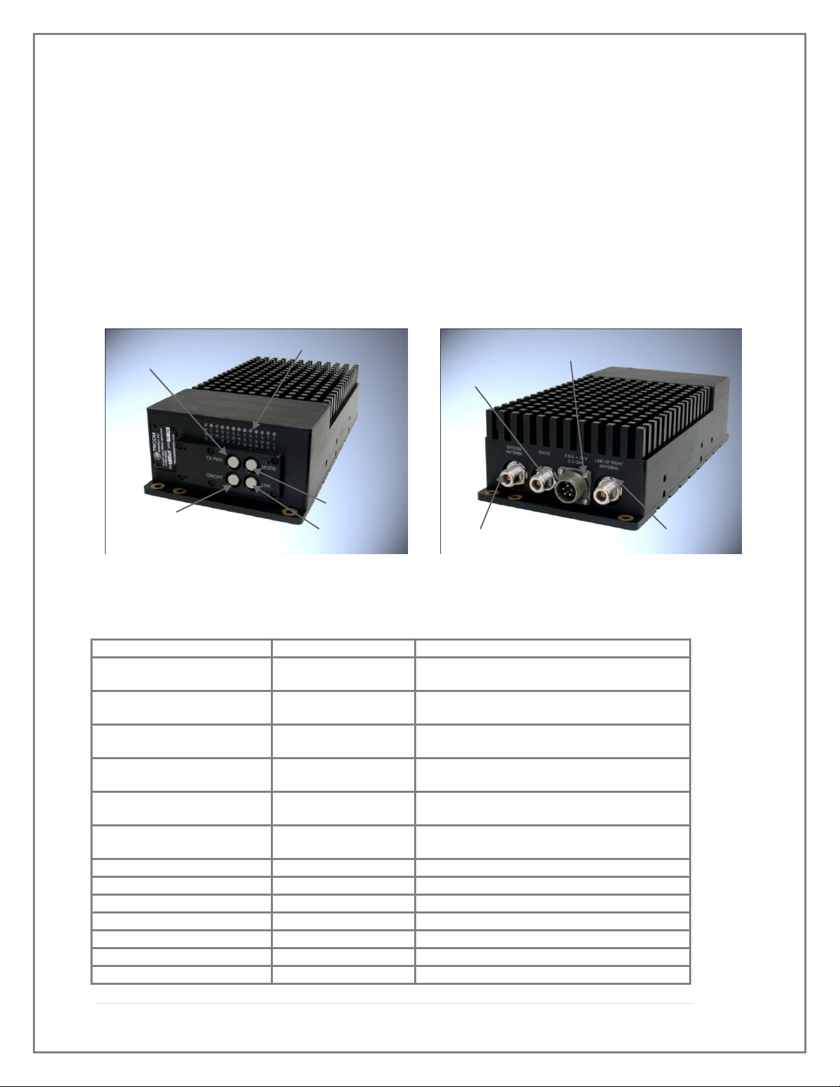
2.2 Controls, Indicators, and Connectors
The TCR-MBA-75 NBT has push Button switches to control:
On/ Off (Bypass)
Transmit power selection (35, 50 or 75 Watts – SATCOM only)
Operational mode (SATCOM, LOS, LOS AM, FHOP, FHOP AM)
DC Power (amplifier bypass to LOS power in off)
There are also several status indicators on the Amplifier's front panel as shown in Figures
2-1. The functions of these are specified in Tables 2-1 and 2-2.
Figure 2-1. Amplifier Controls & Indicators Figure 2-2. Amplifier Connections
INDICATOR TYPE FUNCTION
PWR LED Indicates that DC power is supplied to the
amplifie
r
and the amplifier is powered on
LOS
LED Indicates the Line of Sight connection has been
enable
d
AM LED Indicates the amplifier AM mode of operation
has been enable
d
SAT LED Indicates the SATCOM connection has been
enable
d
HOP LED Indicates the amplifier frequency hopping
mode of operation has been enable
d
XMT LED Indicates that the amplifier is in the transmit
mode
LNA LED Indicates tha
t
the Low Noise Amplifier is on
35W LED Indicates the amplifier is in 35Watt mode
50W LED Indicates the amplifier is in 50Watt mode
75W LED Indicates the amplifier is in 75Watt mode
TMP LED Indicates a hi
g
h temperature condition exists
FLT LED Indicates a fault condition exists
SAT ANT Output
Mode
On/Of
f
RF PWR ADJ
LNA on/off
LNA on/off
LED Indicators
Radio RF In
p
ut
DC Input
LOS Ant Output
8 | Page
Table 2-1. TCR-MBA-75 NBT Controls, Indicators, and Connectors
2.3 Operational Procedures
2.3.1 General Information
The TCR-MBA-75 NBT can be used for operation once it has been installed as
described in Section 3.
2.3.2 Equipment Set-up
Refer to Paragraph 2.2 for the locations and functional description of the controls
and indicators. Make sure that the TCR-MBA-75 NBT has been installed according to
the instructions provided in Section 3.
2.3.3 Operating Procedures
2.3.3.1 Normal Operation
In Normal operation, the TCR-MBA-75 NBT provides transmit power amplification for
radios operating in the 30-512 MHz VHF and UHF bands. It also provides for receive
gain amplification in SATCOM Mode. The Mode switch provides selection for either the
SATCOM, LOS (Line of Sight), Frequency Hopping and AM or FM modes (Refer to
Table 2.1 Controls, Connectors and Indicators and Figure 2-3. flow chart for
information). RF output to the SATCOM or LOS antenna ports is automatically selected
and determined by the mode selected.
2.3.3.1.1 Switch Operation
Mode- When SATCOM is selected using the Mode Push Button Switch; RF is routed to
the SATCOM RF port. This allows selectable RF output power using the TX PWR
adjust push button switch. When in SATCOM mode the user can select to turn on the
Low Noise Amplifier on to increase Receive gain sensitivity. The LNA option is enabled
or disabled using the LNA Push Button Switch to provide an average 10dB receive gain
for use in disadvantaged installations where either Omni-directional SATCOM antennas
are used or when there are long runs of RF cable loss to overcome.
CONNECTION TYPE FUNCTION
SATCOM ANTENNA
N
T
y
pe RF connecto
r
Used to attach SATCOM Antenna
RADIO
N
T
y
pe RF Connecto
r
Used to attach to Transceive
r
Line Of Si
g
ht Antenna
N
T
y
pe RF Connecto
r
Used to attach Line of Si
g
ht Antenna
DC Power input connection Circular Mil connecto
r
Used to attach DC power input to amplifie
r
CONTROLS TYPE FUNCTION
TX Powe
r
Push to selec
t
Selects RF power output in SATCOM Mode
ON/OFF Hold to turn on/off Selects ON or Off (B
y
pass) mode of operation
MODE Push to selec
t
Selects the mode of operation
LNA Push to selec
t
Turns LNA ON and OFF

9 | Page
TX PWR- The transmit power switch selects the power level for SATCOM operation.
The default transmit power for LOS operation is 50 Watts FM and 25 W CW AM and is
not controlled by the transmit power switch.
LNA-The LNA push button switch selects whether the LNA is On or Off when in the
SATCOM mode of operation. In LOS operation the LNA is automatically disabled.
ON/OFF- To power on or power off the TCR-MBA-75 NBT the ON/Off push button
switch must be held down for approximately 2 seconds. The ON/OFF push button switch
cycles the TCR-MBA-75 NBT from power On to power Off Bypass mode. In Power Off
Bypass the RF is automatically routed to the LOS antenna port directly from the
transceiver. The Amplifier returns to the previous operational mode when power is
cycled.
2.3.3.2 MBITR Specific Operation
There may be an interoperability issue when operating the MBITR radio with
amplifiers that have a receive Low Noise Amplifier (LNA). Using the LNA ON setting
with the MBITR may cause intermittent Squelch break on the radio. To resolve this
Fi
g
ure 2-3. Mode, RF
p
ower and LNA flow Chart
10 | Page
possible issue simply turn the LNA operation off via front panel LNA Push Button
Switch selection.
2.3.3.3 Remote Operation
The TCR-MBA-75 NBT can be powered remotely using the Bias Tee I, the same
Bias Tee used with the AM-SAT-50 and AM-SAT 100 (See Figure 2-4). When DC
power is supplied from a conditioned 24-28 Volt source to the Bias Tee (circular Mil
connector), and the On/Off switch is in the On position, power will be routed to the TCR-
MBA-75 NBT via the RF cable that is attached between the Bias Tee (To Amplifier) and
Radio input connector on the amplifier (refer to figure 2-5).
To power on the TCR-MBA-75 NBT the ON/Off switch on the Bias Tee must be
in the On position and then the user must also press the ON/OFF button on the TCR-
MBA-75 NBT for approximately 2 seconds.
The Amplifier will power down if the RF cable (to the amplifier) is removed or if
the power at the Bias Tee input is interrupted. The unit will not automatically power on
when the RF cable (to the amplifier) or the DC at the Bias tee power is restored without
also pressing the ON/OFF button at the amplifier.
Figure 2-4. Bias Tee I for remote operation

11 | Page
2.3.3.4 Out of Band Operation
Operating outside of the UHF SATCOM frequency bands with the SATCOM
mode selected will cause an alarm to occur. Returning to the receive mode will clear the
transmit frequency fault alarm.
Operating on SATCOM frequencies while in the LOS mode with an antenna
connected to the LOS port will not cause an alarm and it will operate properly, however,
the amplifier will not comply with the timing requirements for DAMA operation.
2.3.3.5 Bypass Operation
When DC power is removed or when the AMP Bypass position is selected the
radio port is directly connected to the LOS antenna port.
2.3.3.6 Troubleshooting
If the communications system seems to be operating improperly, check to make
sure that the equipment is configured in accordance with Section 2 Operation and section
3 Installation. If the problem persists follow the instructions below.
2.3.3.7 Collocation
Figure 2-5. Remote Operation Setup

12 | Page
Collocation with other transmitters or ECM/ECCM equipment. The TCR-MBA-
75 attempts to prevent high levels of RF energy present in dense antenna or jamming
environments from inadvertently keying the amplifier. If this condition exists there may
be intermittent keying or chattering of the equipment and its TX indicator. Increased
isolation from the offending RF power source will help to reduce the condition, if
present.
Table 2-2. TCR-MBA-75 NBT System Troubleshooting Guide
SYMPTOM PROBABLE CAUSE SUGGESTED FIX
XMT light flashes
when transmitting
TMP Led Lite
Low output power
Incorrect operating
frequency for selected
mode
Excessive heat build-up
Low input voltage or
drive level
Change mode or frequency for
proper operation
Decrease duty cycle or provide
increased ventilation
Check DC voltage while
transmitting and radio output
power setting
FLT LED Lit Internal Processor error Cycle power to clear. If persists
return to manufacture for
dia
g
nosis
3.0 INSTALLATION
3.1 General Information
This section contains information necessary for preparing the TCR-MBA-75 NBT
for use.
3.2 Preparation for Use
After unpacking the system and inspecting for physical damage, select an
appropriate location for the Amplifier. Although the Amplifier is weather-resistant,
placing it in a location where it is protected from direct salt spray, rain, and sunlight will
increase its service life. Make sure that adequate air flow is available to keep the heat
sink of the amplifier cool.
3.3 Cable Interconnections
Attach the DC power source to the DC IN connector located on the rear or the amplifier (See
Fig 3-1 and Table 3-1 for connector pinout and location). Attach an RF cable to the input
from the transceiver to the Radio input Connector. Attach RF cables/antennas to either one or
both of the antenna connections located on the rear of the amplifier. Select the operating

13 | Page
mode with the push button Mode switch. RF output is routed to the appropriate Antenna
connection determined by the mode selected.
Figure 3-1 Amplifier DC input connector
Table 3-1. DC Input Power
Connector Pin Out
Pin # Connection
Pin
A
+28V DC
(
positive
)
Pin B +28V DC
(
positive
)
Pin C Ground
(
ne
g
ative return
)
Pin D Ground
(
ne
g
ative return
)
Pin E +28V DC
(
positive
)
14 | Page
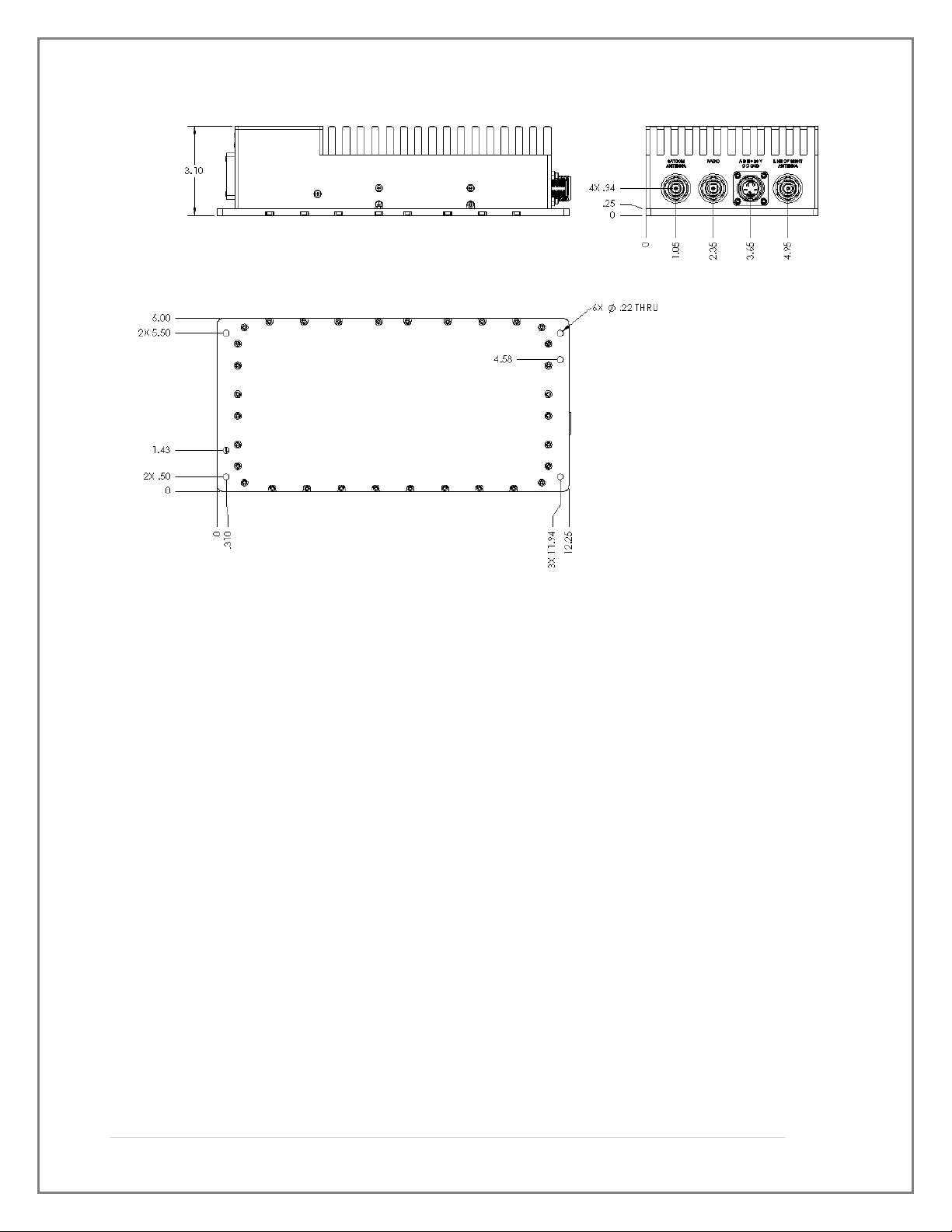
Figure 3-2 Amplifier Mounting Dimensions
Other manuals for TCR-MBA-75
1
Table of contents
Other TriCom Amplifier manuals


Popular Amplifier manuals by other brands


K-array
K-array Kommander-KA user guide

Acoustic Image
Acoustic Image Ten2 EX owner's manual

Roksan Audio
Roksan Audio Attessa Set Up Guide and Product Manual

Lab.gruppen
Lab.gruppen fP Series FP 2400Q Service manual

Stage Accompany
Stage Accompany EFFICIENCY SERIES ES 20 user manual

Soundstream
Soundstream Reference Series 200 Owner's manual and installation guide


