FMS EMGZ421 User manual

Operating Manual EMGZ421
Digital microprocessor controlled
Double Channel Tension Measuring Amplifier
Version 2.05 05/04 sd
This operation manual is also available in german, french and italian.
Please contact your local representative.
Diese Bedienungsanleitung ist auch in deutsch, französisch und italienisch erhältlich.
Bitte kontaktieren Sie die Vertretung im zuständigen Land.
Ce mode d'emploi est également disponible en français, en italien et en allemand.
Veuillez contacter la représentation locale.
Queste manuale d’installazione è disponibile anche in lingua italiano, francese e tedesco.
Vogliate cortesemente contattare la locale rappresentanza.
© by FMS Force Measuring Systems AG, CH-8154 Oberglatt – All rights reserved.

Operating Manual EMGZ421
2
1Safety Instructions
1.1 Description conditions
a) High danger of health injury or loss of life
Danger
This symbol refers to high risk for persons to get health injury or loss life. It has to be
followed strictly.
b) Risk of damage of machines
Caution
This symbol refers to informations, that, if ignored, could cause heavy mecanical damage.
This warning has to be followed absolutely.
c) Note for proper function
Note
This symbol refers to an important information about proper use. If not followed,
malfunction can be the result.
1.2 List of safety instructions
Proper function of the tension measuring amplifier is only guaranteed with the
recommended application of the components. In case of other arrangement, heavy
malfunction can be the result. Therefore, the installation instructions on the
following pages must be followed strictly.
Local installation regulations are to preserve safety of electric equipment. They are not
taken into consideration by this operating manual. However, they have to be followed
strictly.
Bad earth connection may cause electric shock to persons, malfunction of the total
system or damage of the measuring amplifier! It is vital to ensure that proper earth
connection is done.
The processor board is mounted directly behind the operation panel. Improper
handling may damage the fragile electronic equipment! Don’t use rough tools as
screwdrivers or pliers! Don’t touch processor board! Touch earthed metal part to
discharge static electricity before removing operation panel!
Some contacts on the power supply are under 110V resp. 230V tension! Mortal
danger! Disconnect power supply before open the housing!

Operating Manual EMGZ421
3
Table of contents
1Safety Instructions ....................................................................................2
1.1 Description conditions 2
1.2 List of safety instructions 2
2Definitions..................................................................................................4
3System components...................................................................................4
4System Description....................................................................................5
4.1 Functional description 5
4.2 Force sensors 5
4.3 Electronic unit EMGZ421 5
5Quick installation guide............................................................................7
6Dimensions.................................................................................................8
6.1 Dimensions: Variant for insert card support block (EMGZ421) 8
6.2 Dimensions: Variant with separate housing (EMGZ421.E) 8
7Installation and wiring..............................................................................9
7.1 Mounting and wiring of the measuring amplifier 9
7.2 Mounting the force sensors 9
7.3 Wiringdiagram:Variant forinsert cardsupport block (EMGZ421) 10
7.4 Wiring diagram: Variant with separate housing (EMGZ421.E) 10
8Operation .................................................................................................12
8.1 View of the operating panel 12
8.2 Calibrating the measuring amplifier 13
8.3 Additional settings 15
9Serial interface (RS232)..........................................................................16
9.1 Wiring diagram: RS232 interface 16
9.2 Command list 16
9.3 Read parameter 17
9.4 Write parameter 18
10 Parametrization.......................................................................................19
10.1 Parameter list 19
10.2 Schematic diagram of parametrization 20
10.3 Description of the parameters 21
11 Trouble shooting......................................................................................28
12 Technical data EMGZ421 ......................................................................30

Operating Manual EMGZ421
4
2Definitions
Offset: Correction value for compensation of the zero point difference. Thanks to the
offset, it is ensured that a force of 0N will generate a signal of 0V exactly.
Gain: Amplification factor for the measuring signal. Use of proper value will set the
measuring range of the sensor exactly corresponding to the signal output range (0...10V).
Strain gauge: Electronic component that will change its resistance while its length has
changed. Strain gauges are used in the FMS force sensors for acquisition of the feedback
value.
3System components
The EMGZ421 consists of the following components (refer also to fig. 1):
Force sensors
•For mechanical/electrical conversion of the tension force
•Force measuring bearing
•Force measuring roller
•Force measuring journal
•Force measuring bearing block
Electronic unit EMGZ421
•For supplying of the force sensors and amplifying of the mV signal
•Two separated analogue inputs for the sensors of a single measuring point
•With operation panel for parametrization
•Interface RS232
•Interface CAN-Bus
•For mounting into insert card support block EMGZ555959 (by mounting into control
cabinet)
•Mounted in separate housing (EMGZ421.E)
•Integrated power supply (by using separate housing)
•Supports connection of an external feedback display
(Italic text indicates variant or option)

Operating Manual EMGZ421
5
4System Description
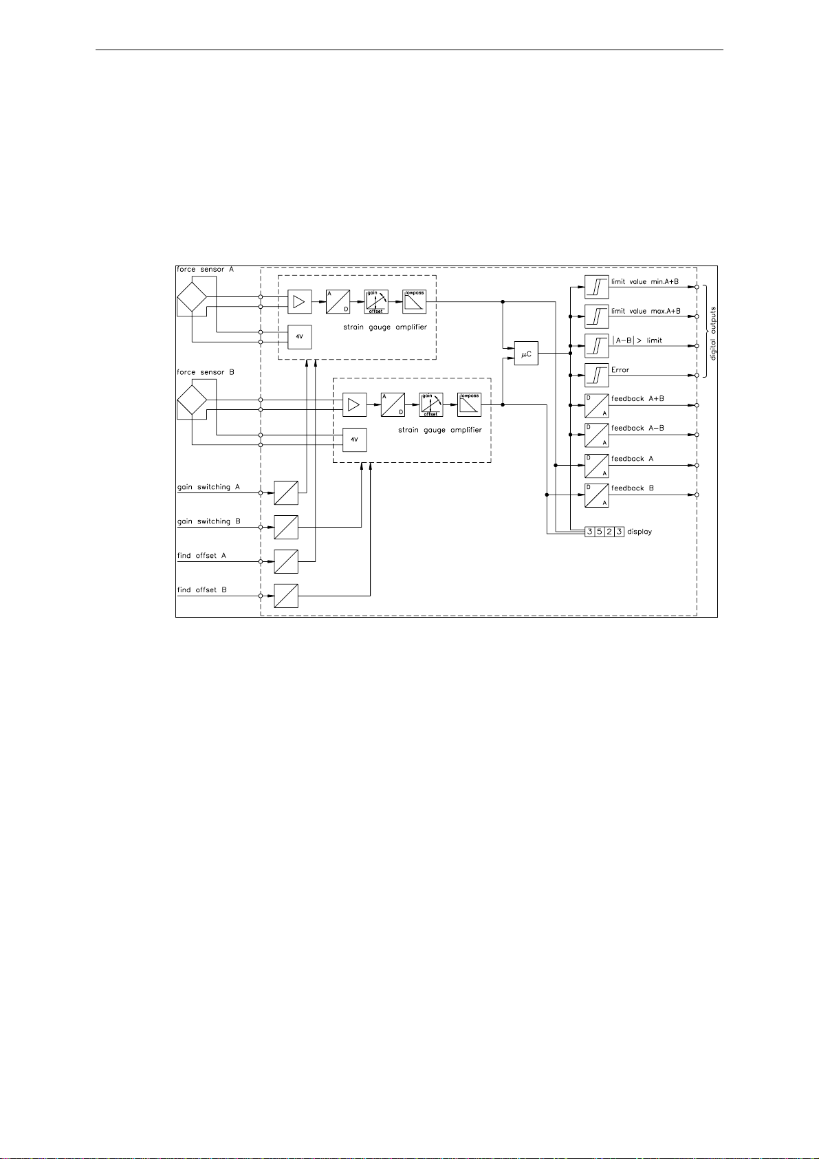
fig. 1: Basic structure of the EMGZ421 tension measuring amplifier E421001e
4.1 Functional description
The EMGZ421 is a double channel strain gauge amplifier for a single measuring point.
The material tension can be measured on both sides of the measuring roller
independently.
The 2 force sensors of the measuring point measure the tension force in the material and
transmit the measuring value as a mV signal to the electronic unit EMGZ421. The
electronic unit amplifies the mV signal of each force sensor independently. A sum value
(A+B) and a difference value (A–B) is calculated from the force values of the sensors A
and B. The resulting feedback values are shown in the display in [N]. In addition, the
feedback values are provided at the analogue outputs and can be evaluated by analogue
instruments, a PLC or equivalent devices.
4.2 Force sensors
The force sensors are based on the flexion beam principle. The flexion is measured by
strain gauges and transmitted to the electronic unit as mV signal. Due to the wheatstone
wiring of the strain gauges, the measured value is according also to the power supply. So,
the force sensors are supplied from the EMGZ421 by a very accurate power supply.
4.3 Electronic unit EMGZ421
Common
The electronic unit contains a microprocessor to handle all calculations and
communications, the highly accurate sensor power supply and the signal amplifier for the
measuring value. As operation interface it provides 4 keys, 4 LED’s and a 2x16
characters display in the front of the electronic unit. All inputs are saved in an EEPROM.
The electronic unit has no jumpers or trimmers to keep most accurate long-time and
temperature stability.
Strain gauge amplifier
The strain gauge amplifier provides the highly accurate 4V power supply. A highly
accurate, fixed difference amplifier rises the mV signal up to 10V. This signal will be fed
to the A/D converter. The microprocessor then does all application-specific calculations
with the digitized measuring value (such as offset, gain, low-pass filter, limit switches,
etc).

Operating Manual EMGZ421
6
Using digital inputs, the amplifier can be switched easily between 2 different gain
parameters (for ex. to process different operating conditions). There is no reconfiguration
required to switch the gain parameters.
The strain gauge amplifier section written above is integrated twice to provide
independent evaluation of each force sensor.
Interface
As standard, the electronic unit supports an RS232 interface. As an option, there is an
additional board with CAN-Bus interface available.
fig. 2: Block diagram of the electronic unit EMGZ421 E421002e

Operating Manual EMGZ421
7
5Quick installation guide
•Check all your requirements such as:
– configuration of the analogue outputs (signal level)?
– gain switching required?
– linking by serial interface etc.?
•Draw your final wiring diagram according to the wiring diagrams (refer to „7.3 Wiring
diagram variant for insert card support block“ / „7.4 Wiring diagram variant with
separate housing“)
•Install and wire all your components (refer to „7. Installation and wiring“)
•Parametrize and calibrate the measuring amplifier (refer to „8.2 Calibrating the
measuring amplifier“)
•Put system into operation; proceed a test run with low speed
•If required, do additional settings (refer to „8.3 Additional settings“)

Operating Manual EMGZ421
8
6Dimensions
6.1 Dimensions: Variant for insert card support block (EMGZ421)
fig. 3: Dimensions of the variant using insert card support block (EMGZ400 series).
The support block EMGZ555959 has to be ordered separately. E411004us
If the electronic unit should be mounted into a 19“ rack, a multipoint plug is used instead
of the support block.
6.2 Dimensions: Variant with separate housing (EMGZ421.E)
fig. 4: Dimensions of the variant using separate housing (option, EMGZ400.E series)
E411005e

Operating Manual EMGZ421
9
7Installation and wiring
Caution
Proper function of the tension measuring amplifier is only guaranteed with the
recommended application of the components. In case of other arrangement, heavy
malfunction can be the result. Therefore, the installation instructions on the following
pages must be followed strictly.
Caution
Local installation regulations are to preserve safety of electric equipment. They are not taken
into consideration by this operating manual. However, they have to be followed strictly.
7.1 Mounting and wiring of the measuring amplifier
Variant for insert card support block (EMGZ421)
The insert card support block can be mounted in a control cabinet. Wiring to the terminals
is done according to „7.3 Wiring diagram: Variant for insert card support block“ (fig. 5).
The electronic unit then will be inserted into the insert block. It will be locked by a stop
hook (fig. 3).
Variant with separate housing (EMGZ421.E)
The housing can be mounted in a control cabinet or directly beside the machine. All
connections are led through glands to the screw terminals and connected according to
„7.4 Wiring diagram: Variant with separate housing“ (fig. 6 and 7).
7.2 Mounting the force sensors
Mounting of the force sensors is done referring to the FMS Installation manual which is
delivered together with the force sensors.
Wiring to the terminals of the electronic unit is done according to wiring diagram (fig. 5
resp. 6).
Note
Connecting the shield of the signal cable to the measuring amplifier and to the force
sensor may cause ground circuits which may interfere the measuring signal massively.
Malfunction can be the result. The shield should be connected only to the measuring
amplifier. On the „force sensor side“, the shield should stay open.

Operating Manual EMGZ421
10
7.3 Wiring diagram: Variant for insert card support block (EMGZ421)
fig. 5: Wiring diagram: Variant for insert card suppor block E421005e
Caution
Bad earth connection may cause electric shock to persons, malfunction of the total system
or damage of the measuring amplifier! It is vital to ensure that proper earth connection is
done.
7.4 Wiring diagram: Variant with separate housing (EMGZ421.E)
The housing of the electronic unit will be opened by unscrewing the 4 philips screws on
the operation panel and swinging out the operation panel to the right side.
Caution
The processor board is mounted directly behind the operation panel. Improper handling
may damage the fragile electronic equipment! Don’t use rough tools as screwdrivers or
pliers! Don’t touch processor board! Touch earthed metal part to discharge static
electricity before removing operation panel!
Danger
Some contacts on the power supply are under 110V resp. 230V tension! Mortal danger!
Disconnect power supply before open the housing!

Operating Manual EMGZ421
11
fig. 6: Wiring diagram: Variant with separate housing E421010e
fig. 7: Screw terminal arrangement on terminal board E411001e

Operating Manual EMGZ421
12
8Operation
8.1 View of the operating panel
fig. 8: Operating panel: Variant for insert card support block (EMGZ421) E421006e
fig. 9: Operating panel: Variant with separate housing (EMGZ421.E) E421007e

Operating Manual EMGZ421
13
8.2 Calibrating the measuring amplifier
Parametrizing the measuring amplifier
The following parameters have to be set resp. to be checked before the first calibration is
done (ref. to „10. Parametrisation“):
•Nominal force sensor A
•Nominal force sensor B
•Unit of force
•Sensitivity sensor A
•Sensitivity sensor B
•Scale output 1
•Scale output 2
•Scale output 3
•Scale output 4
Simulating Method (recommended)
The following instructions are referring to
a setup and calibration on-site. The
material tension will be simulated by a
weight (fig. 10).
•Connect both force sensors (A and B).
•Check, if a positive value is displayed
when loading the sensor A in
measuring direction. If not, exchange
terminals z6 / z8 (resp. 2 / 3)
•Check, if a positive value is displayed
when loading the sensor B in
measuring direction. If not, exchange
terminals d6 / d8 (resp. 7 / 8)
•Insert material or a rope loosely to the
machine
•Adjust offset A by activating the
parameter function find offset A and
pressing the ↵key for 3 seconds (ref.
to „10. Parametrisation“). The electronic unit calculates automatically the new offset
A value.
•Adjust offset B by activating the parameter function find offset B and pressing the ↵
key for 3 seconds (ref. to „10. Parametrisation“). The electronic unit calculates
automatically the new offset B value.
•Load material or rope with a defined weight (fig. 10)
•Activate parameter function Calibration A. Input the force referring to half of the
applied weight (refer to „10. Parametrization“). The electronic unit calculates
automatically the new gain A value.
•Activate parameter function Calibration B. Input the force referring to half of the
applied weight (refer to „10. Parametrization“). The electronic unit calculates
automatically the new gain B value.
•Quit calibration with Home key.
fig. 10: Calibrating the measuring
amplifier C431011e

Operating Manual EMGZ421
14
Mathematical method
If the material tension cannot be simulated, calibration has to be done by calculation. This
way of calibrating is less accurate because the exact angles are often unknown and the
effective mounting conditions, which usually deviate from the ideal, are not taken into
account.
•Offset adjustment has to be done as described under „Simulating method“.
•The Gain value will be calculated by the following formula and then inputted in the
parameters gain channel A / gain channel B (refer to „10. Parametrization“).
fig. 11: Force vectors in the FMS force measuring bearing C431012e
Definition of symbols:
αangle between vertical and measuring
web axis FBmaterial tension
βangle between vertical and FMF
Groller weight
γmaterial wrap angle FMmeasuring force resulting from FB
γ1entry angle of material FMeff effective measuring force
γ2exit angle of material
δAngle between measuring web axis and FM
()
22/sinsin 1
⋅⋅
==
γδ
ckBGainFeedbackAGainFeedba

Operating Manual EMGZ421
15
8.3 Additional settings
Setting of the lowpass filters
The measuring amplifier provides 5 lowpass filters independently adjustable from each
other. They are used to prevent noise which is added to the signals. Signal variations
which are faster than the cut-off frequency are then suppressed. The lower the cut-off
frequency, the more sluggish the output signal will be.
The lowpass filters are configured by setting its cut-off frequency to an appropriate value.
The cut-off frequency is set in the parameter Lowpass display resp. Lowpass output 1...4
(ref. to „10. Parametrisation“).
Note
If the cut-off frequency is set to a value too low, the output signal will become sluggish.
It may be that the feedback value is no longer suitable for control loop applications. You
have to pay attention that the cut-off frequency is set to a suitable value.
Setting of the limit switches
The measuring amplifier provides 3 limit switches which can be tapped at the digital
outputs (terminals b10 / b12 / b14 resp. 27 / 28 / 29). The limit switches are actuated
when the feedback value exceeds (Limit value max.A+B) resp. undershoots (Limit value
min.A+B) the force values stored in parameters Minimum limit A+B resp. Maximum limit
A+B. The limit switch |A–B| > limit is actuated if the difference of the 2 measuring values
is higher than the force stored in parameter |A–B| > limit.
Tapping of the limit switches is done according to wiring diagram (fig. 5 or 6).
Scaling of the analogue outputs
With default setting, the analogue outputs give the maximum signal (10V resp. 5V) when
the nominal force of the sensors is reached. The output signal level can be customized
with the parameters Scale output 1...4.
Gain switching
If a measuring point is operated with varying measuring conditions (for ex. different
material paths), the gain factor of each channel may be switched between 2 values
depending on the material path. Switching is done using the digital inputs „Gain switching
A“ resp. „Gain switching B“. Therefore, the extra gain values have to be calibrated during
setup too (ref. to parameters Cal. gain 1 A / Cal. gain 1 B / Gain 1 channel A / Gain 1
channel B).
Tare function
If parameter Config. of key is set to TareA, TareB or TareA+B, pressing the ↓key will set
the display and the feedback value of the specified output channel to zero. Therefore,
variations of the display during retooling may be compensated.
The original offset value remains in the measuring amplifier. If the ↓key is pressed
again, the original offset value is restored; display and output signal show the original
feedback value.

Operating Manual EMGZ421
16
9Serial interface (RS232)
The serial interface is operated for example by a personal computer as a kind of „question
and answer“ game: The PC sends a question resp. a command; the measuring amplifier
will send an answer back. If the answer is missing, the measuring amplifier or the
connection cable may fail.
9.1 Wiring diagram: RS232 interface
fig. 12: Wiring diagram RS232 interface E400001e
Reliable connection using maximum baudrate (9600) is guaranteed up to wire length of
10m. If the baudrate is reduced and/or good conditions prevail, considerably greater
distances can be bridged in some cases.
Connection to a PC etc. is done with a 9- or 25-pole Sub-D connector.
9.2 Command list
command answer purpose
ERR?<CR> XXXXXX<CR> read actual errors
Pos. 1...6 : Err1...Err6
Value of Pos. = 0 : No Err;
Value of Pos. = 1 : Err active
IDNT<CR> EMGZ421 V2.01 1198 10 characters type, fix
< Type > <Version> <S > 10 characters version, fix
4 characters serial number, fix
INRS<CR> PACC<CR> / FAIL<CR> initialize interface
(for ex. after loading of new
interface parameters)
REMR<CR> PACC<CR> / FAIL<CR> turn off remote mode
(enabling the keys on the
operating panel)
REMS<CR> PACC<CR> / FAIL<CR> turn on remote mode
(disabling the keys on the
operating panel)
VALS<CR> XXXXXX<CR> read feedback value A+B
VALD<CR> XXXXXX<CR> read feedback value A–B
VALA<CR> XXXXXX<CR> read feedback value A
VALB<CR> XXXXXX<CR> read feedback value B

Operating Manual EMGZ421
17
9.3 Read parameter
command answer purpose
RP01<CR> XXXXX<CR> Offset channel A
RP02<CR> X.XXX<CR> Gain channel A
RP03<CR> XXXXX<CR> Offset channel B
RP04<CR> X.XXX<CR> Gain channel B
RP05<CR> X.XXX<CR> Gain1 channel A
RP06<CR> X.XXX<CR> Gain1 channel B
RP07<CR> XXXX<CR> Nominal force sensor A
RP08<CR> XXXX<CR> Nominal force sensor B
RP09<CR> X<CR> Unit of force
RP10<CR> X.X<CR> Sensitivity sensor A
RP11<CR> X.X<CR> Sensitivity sensor B
RP13<CR> XXXXX<CR> Min. limit value A+B
RP14<CR> XXXXX<CR> Max. limit value A+B
RP15<CR> XXXXX<CR> |A–B| > limit
RP18<CR> XX.X<CR> Lowpass display
RP19<CR> XXX.X<CR> Lowpass output 1 (A–B)
RP20<CR> XXX.X<CR> Lowpass output 2 (A+B)
RP21<CR> XXX.X<CR> Lowpass output 3 (A)
RP22<CR> XXX.X<CR> Lowpass output 4 (B)
RP23<CR> XX.XX<CR> Scale output 1 (A–B)
RP24<CR> XX.XX<CR> Scale output 2 (A+B)
RP25<CR> XX.XX<CR> Scale output 3 (A)
RP26<CR> XX.XX<CR> Scale output 4 (B)
RP28<CR> X<CR> Language
RP29<CR> X<CR> Config. of key
RP39<CR> XXX<CR> Identifier
RP40<CR> X<CR> Baud rate RS232
RP41<CR> X<CR> 7 or 8 data bit
RP42<CR> X<CR> 1 or 2 stop bit
RP43<CR> X<CR> Parity bit RS232
All parameter numbers and input ranges refer to the parameter list.

Operating Manual EMGZ421
18
9.4 Write parameter
command answer purpose
WP01XXXXX<CR> PACC<CR> / FAIL<CR> Offset channel A
WP02X.XXX<CR> PACC<CR> / FAIL<CR> Gain channel A
WP03XXXXX<CR> PACC<CR> / FAIL<CR> Offset channel B
WP04X.XXX<CR> PACC<CR> / FAIL<CR> Gain channel B
WP05X.XXX<CR> PACC<CR> / FAIL<CR> Gain1 channel A
WP06X.XXX<CR> PACC<CR> / FAIL<CR> Gain1 channel B
WP07XXXX<CR> PACC<CR> / FAIL<CR> Nominal force sensor A
WP08XXXX<CR> PACC<CR> / FAIL<CR> Nominal force sensor B
WP09X<CR> PACC<CR> / FAIL<CR> Unit of force
WP10X.X<CR> PACC<CR> / FAIL<CR> Sensitivity sensor A
WP11X.X<CR> PACC<CR> / FAIL<CR> Sensitivity sensor B
WP13XXXXX<CR> PACC<CR> / FAIL<CR> Min. limit value A+B
WP14XXXXX<CR> PACC<CR> / FAIL<CR> Max. limit value A+B
WP15XXXXX<CR> PACC<CR> / FAIL<CR> |A–B| > limit
WP18XX.X<CR> PACC<CR> / FAIL<CR> Lowpass display
WP19XXX.X<CR> PACC<CR> / FAIL<CR> Lowpass output 1 (A–B)
WP20XXX.X<CR> PACC<CR> / FAIL<CR> Lowpass output 2 (A+B)
WP21XXX.X<CR> PACC<CR> / FAIL<CR> Lowpass output 3 (A)
WP22XXX.X<CR> PACC<CR> / FAIL<CR> Lowpass output 4 (B)
WP23XX.XX<CR> PACC<CR> / FAIL<CR> Scale output 1 (A–B)
WP24XX.XX<CR> PACC<CR> / FAIL<CR> Scale output 2 (A+B)
WP25XX.XX<CR> PACC<CR> / FAIL<CR> Scale output 3 (A)
WP26XX.XX<CR> PACC<CR> / FAIL<CR> Scale output 4 (B)
WP28X<CR> PACC<CR> / FAIL<CR> Language
WP29X<CR> PACC<CR> / FAIL<CR> Config. of key
WP39XXX<CR> PACC<CR> / FAIL<CR> Identifier
WP40X<CR> PACC<CR> / FAIL<CR> Baud rate RS232
WP41X<CR> PACC<CR> / FAIL<CR> 7 or 8 data bit
WP42X<CR> PACC<CR> / FAIL<CR> 1 or 2 stop bit
WP43X<CR> PACC<CR> / FAIL<CR> Parity bit RS232
All parameter numbers and input ranges refer to the parameter list. Depending on the
value being ok or not, the electronic unit replys PACC<CR> (value accepted) or
FAIL<CR> (value not accepted).

Operating Manual EMGZ421
19
10 Parametrization
10.1 Parameter list
Parameter Unit Default Min Max Selected
Find offset A (Parameter function)
Calibration A (Parameter function) _______
Find offset B (Parameter function)
Calibration B (Parameter function) _______
Cal. gain 1 A (Parameter function) _______
Cal. gain 1 B (Parameter function) _______
Offset channel A [Digit] 0 –4000 4000 _______
Gain channel A [-] 1.000 0.100 9.000 _______
Offset channel B [Digit] 0 –4000 4000 _______
Gain channel B [-] 1.000 0.100 9.000 _______
Gain 1 channel A [-] 1.000 0.100 9.000 _______
Gain 1 channel B [-] 1.000 0.100 9.000 _______
Nominal force sensor A [N,kN] 1000 1 9999 _______
Nominal force sensor B [N,kN] 1000 1 9999 _______
Unit of force N, kN N _______
Sensitivity sensor A [mV/V] 1.8 0.1 3.0 _______
Sensitivity sensor B [mV/V] 1.8 0.1 3.0 _______
Min. limit A+B [N, kN] 0 –9999 9999 _______
Max. limit A+B [N, kN] 0 –9999 9999 _______
|A–B| > limit [N, kN] 0 –9999 9999 _______
Lowpass display [Hz] 1.0 0.1 10.0 _______
Lowpass output 1 (A–B) [Hz] 10.0 0.1 200.0 _______
Lowpass output 2 (A+B) [Hz] 10.0 0.1 200.0 _______
Lowpass output 3 (A) [Hz] 10.0 0.1 200.0 _______
Lowpass output 4 (B) [Hz] 10.0 0.1 200.0 _______
Scale output 1 (A–B) [-] 0.50 0.01 10.00 _______
Scale output 2 (A+B) [-] 0.50 0.01 10.00 _______
Scale output 3 (A) [-] 1.00 0.01 10.00 _______
Scale output 4 (B) [-] 1.00 0.01 10.00 _______
Language German, English, French, Italian _______
Config. of key None, TareA, TareB, TareA+B _______
Identifier [-] 0 0 127 _______
Baud rate RS232 300, 600, 1200, 2400, 4800, 9600 _______
7 or 8 data bit [-] 8 7 8 _______
1 or 2 stop bit [-] 1 1 2 _______
Parity bit RS232 None, Odd, Even _______

Operating Manual EMGZ421
20
10.2 Schematic diagram of parametrization
fig. 13 State Diagram EMGZ421 E421009e
This manual suits for next models
1
Table of contents
Other FMS Amplifier manuals