Trident 78 Owners Manual7
Trident 78 Input Channel The Equaliser
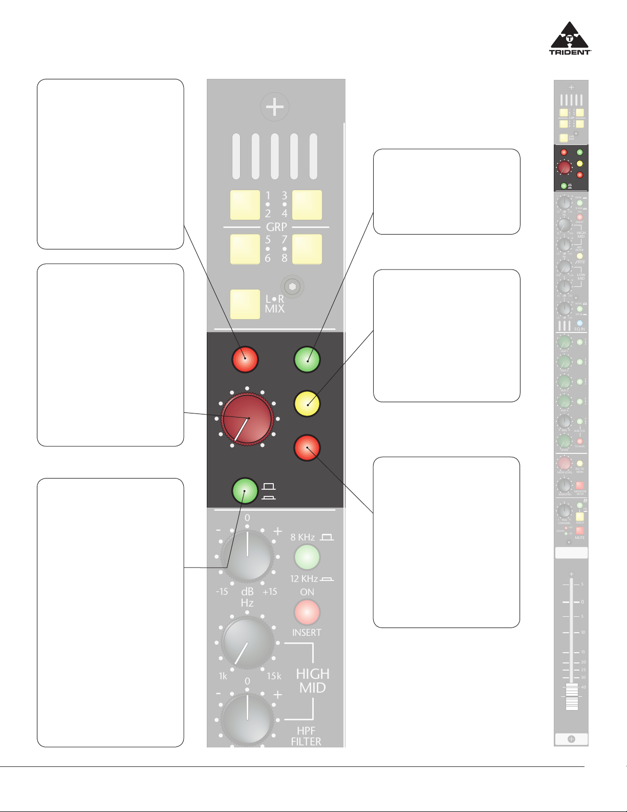
HIGH Frequency
Section – Shelving
Adjusts the high frequency shelving
EQ response. The Level control ad-
justs the cut/boost between +/- 15dB
of the selected “knee” frequency,
this frequency is selectable between
8KHz or 12KHz. The centre “0” posi-
tion of the Level control has a detent
to indicate that it is having no eect
on the associated channel signal. Cut
or boost of the high frequency level
control is usually used for minor tonal
adjustments.
LOW – MID
Frequency Section
Adjusts the low-mid frequency EQ
response. The Frequency control
selects the centre frequency of the
filter (between 100Hz and 1.5kHz)
and the Level control adjusts the cut/
boost between +/- 15dB. The centre
“0” position of the Level control has
a detent to indicate that it is having
no eect on this frequency band. The
bandwidth of this filter is approxi-
mately one octave. The high-mid fre-
quency controls are used for minor
tonal adjustment or repair of a specif-
ic band of frequencies.
LOW Frequency
Section – Shelving
Adjusts the low frequency shelv-
ing EQ response. The Level con-
trol adjusts the cut/boost between
+/- 15dB of the selected “knee” fre-
quency, this frequency is selectable
between 60Hz or 120Hz. The centre
“0” position of the Level control has
a detent to indicate that it is having
no eect on the associated channel
signal. Cut or boost of the low fre-
quency level control is usually used
for minor tonal adjustments.
HIGH – MID
Frequency Section
Adjusts the high-mid frequency EQ
response. The Frequency control
selects the centre frequency of the
filter (between 1KHz and 15kHz) and
the Level control adjusts the cut/
boost between +/- 15dB. The centre
“0” position of the Level control has
a detent to indicate that it is having
no eect on this frequency band. The
bandwidth of this filter is approxi-
mately one octave. The high-mid fre-
quency controls are used for minor
tonal adjustment or repair of a specif-
ic band of frequencies.
INSERT ON
When depressed, this switch places the
rear panel channel insert path to the
Insert Send and back from the Insert
Return in line with the signal path. This
insert point by default is after the chan-
nel EQ. By routing the signal through
this connector, the insert may be used
for applications such as an eect that
can be switched in/out. In the event the
user wants to patch in his/her favourite
external EQ, it can be connected with
its input fed from the Insert Send and
its output feeding the Insert Return,
this path being activated with this
switch, it could be used in conjunction
with/without the Trident EQ.
Channel Equaliser
A four band Trident EQ with overlapping
ranges is provided with a switchable
high pass filter. The HIGH and LOW sections
of the equaliser have a shelving response
(switchable between two frequencies) and the
mids have a peaking (bell) response.
HPF
When selected inserts a high-pass (or
Low- Cut) filter with a corner frequen-
cy 50Hz and a roll o rate of 18dB per
octave into the signal path. This con-
trol is used to remove unwanted sig-
nal content below 50Hz. The result is
usually improved signal quality of the
associated input signal while decreas-
ing the low frequency amplification
demand of the audio systems amplifier
and speaker combination. Mainly for
use with microphones, this helps re-
move low frequency rumble and han-
dling noise.
EQ IN
This switch inserts the 4-band EQ
and High Pass Filter into the channel/
monitor (see EQ TO MON switch de-
scription below) signal path. When not
in use, it is suggested that the EQ be
kept in the OUT position for best phase
performance.