TRILECTRON 90T400SLN User manual
Property of American Airlines
Operator

iE90T400sLN
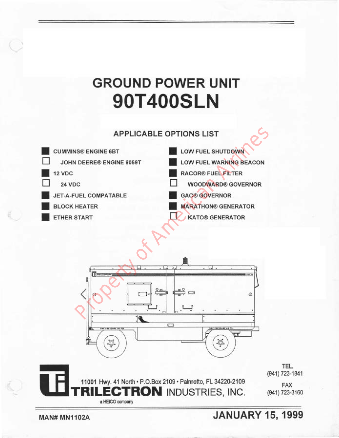
lIIGROUND POWER
UNIT
CHAPTER
1
SECTION
2
OPERATION
1. CONTROLS
ANDINDICATORS
Priortooperating
the
GPU,
personnel
must
become
thoroughly
familiar
withtheoperating
controls,indicatorsand
procedures
described
inthissection.
Refer
tofigure1forillustrated
controllocationand
functionaldescription.
2. OPERATINGPROCEDURES
A. Pre-Operationallnspection:
CAUTION
A PRIOR.TO.USEINSPECTION
MUSTBE
PERFORMEDBEFORE
EACH
OPER,ATION
TOENSURESAFE
AND
RELIABLE
OPERATION
OFTHE
GPU.FAILURETO
PERFORM
THE
PROCEDURES
LISTEDBELOWMAY
RESULTIN
SEVEREDAMAGE
TOTHEEQUIP-
MENT. (1) Enclosure:
Inspect
for
obvious
defects,i.e.,security
ofcommon
hardware.
(2) Towbar:Excessivemovement.
(3) Brakes:Checkbrakesfor
proper
operation.
(4) Tires:Inspecttreadwear,andcheck
tireinflation
(60
psig).
(5) Enginehoses
andclamps:
Inspectforleaks
andsecurity.
(6) RadiatorCoolant:Openforwardcanopy.
Observelevelofcoolantinoverflow
container.
Coolant
shouldbe
nearthe
full
line.
Serviceasrequired
(Refer
to
Section2-2,Servicing).
(7) Oil
level:Openleftfront
accessdoor.
Checkthatoil
levelisatthefullmark
on
thedipstick,
(Refer
tosection2-2,
Servicing).
(8) Fuel
level:SetIGNITION
switchto
ON
position,
observereadingonfuel
gauge.
Service
withfuelasnecessary.
(9) EngineAssembly:
Visually
inspectfuellinesand
fittings
for
evidence
offuel
leakage.lnspectvalve
cover,oil
pan,
andcylinder
blockfor
evidenceofoil
leakage.
(10)FanBelt:Visuallyinspect
forwearandcracking.
Check
beltfor
proper
tension.
(11)AirFilter
(Minder):
Check
FilterMinder@Indicatorlocatedtotheleft
oftheright
front
accessdoor,under
theairfilterassembly.
Replace
airfilterif
areading
of
25orhigher
is
noted
(engine
running).Recheckwhenunitisrunningunder
load.
(12)
EtherStart
(Optional):
Check
etherstartsupplycylinder
installationfor
operationalreadiness.
January
15,1999
Original 1-2
Page1
Property of American Airlines

iE90T400sLN
IJIGROUND POWERUNIT
s-t ///1 \\ ///r \\ \wz i
Fi ir., ll t
lli'lilll,l'lil,
i:
fl
ti
i
il
Iil'
f,:i
ilii
Hi
ilis
ir
Hi iHil
r;
Hlgiiriiiii
Figure1.Engine/Generator
Control
Panel
(Typical)
-SingleAC
UnitShown
January15,
1999
Original
1-2
Page2
Property of American Airlines

it90T400SLN
lIIGROUND POWER
UNIT
2. OPERATINGPROCEDURES(Continued)
B. EngineStartProcedures:
Thefollowingsteps
mustbe
performed
inthe
sequence
in
which
they
are
presented
(See
Figure1):
WARNING
DONOT
CONNECTLIVEPOWER
CABLETOAIRCRAFT.
SEVERE
ELECTRICAL
ARCING
MAYCAUSE
SERIOUS
INJURY,DEATHAND
OR
DAMAGE
TO
THE
EQUIPMENT.
January
15,1999
Original 1-2
Page
3
Figure
1. Control
Panel
Gomponent
tdentification
Item Description
,| CONTROL
PANEL
ASSEMBLY:
Mounted
atfront
ofelectronic
boxassembly
2ACVOLTMETER:
Shows
generator
(L-N)
output
voltage
(0-150
volts).
3FAULTINDICATORS
-GENERATOR:
Fault
indicatorswillilluminate
red
whenafault
hasoccuned.
Each
faultremoves
voltagefom the
aircraft.Overvolts
&Overload
stops
allvoltaoe
oeneration.
4AMMETER:Indicates
generator
(L-N)
output
cunent.
5FUEL
LEVELGAUGE:Indicates
amountoffuel
remaining
infuel
tank.
6OILPRESSURE
GAUGE:lndicatesengine
oil
pressure.
7FAULTINDICATORS
-ENGINE
(Red):
lndicates
tooperatorthe
protective
system
that
caused
theengine
shutdown,i.e.,
Low
oil
pressure
(10
psi
min.);
EngineOverspeed
(2550
RPM);
Engine
Over
Temperature
(225"F).
8IGNITION
ONINDICATOR
(Yellow):
Lights
whenthe
ENGINECONTROL
PO\/ERswitchisturnedon.
IWATER
TEMPERATUREGAUGE:
Indicatesengine
watertemperature
(225"F
max.).
10 BATTERYVOLTMETER:
lndicatesbatteryvoltage
condition.
Donot
startunitifvoltage
islessthan:10V
on
12V
units
and20Von24Vunits.
11 HOURMETER:
Indicatestotalenginerun
time.
12 START
S\MTCH:Startsengine.Pushbutton,
momentarycontact
switch.
13 FAULT
LAMP
TEST
(Pushbutton):\Mren
pressed
while
unitisin
theRUNmode,itlightsallfaultslamps.
When
pressed
whiletheiqnitionswitchisintheON
position.
itwill
liohtonlvtheenqinefaultlamps.
14 IGNITIONSWTCH
(ON/OFD:
On
position
suppliesstartino
andcontrollinovoltaqes
to
enoinecircuits.
15 PANEL
LIGHTSSWTCH:
Tums
panel
liohts
Onforniohttimeooeration.
16 RUN/IDLESWTCH:Two
position
switch.Controlsengine
speed.
IDLE
position
forstarting.
RUN
position
for
oeneratorooeration.
17 AMMETERSWTCH
(Rotary):
Measurescunent
of
phases
'1.2
or3.
18 FREQUENCYMETER:Shows
qenerator
outputfrequencv
(360-440H2).
19 AC
LOAD
CABLEON
(Push-button):
Supplies
AC
powerto
output
Cable1
(single
and
dualAC
outputunits).
Used
inconjunctionwithINTERLOCI(BY-PASSswitch.\Mren
ONispushed
withINTERLOCK
setting,
GPU
provides
momentary28Y DCtoaircraftconnector
pins
E&F.
AC
LOAD
CABLE
2
ON:SuppliesAC
powerto
outputCable
2.Onlyonunits
withdualACoutput
(See
figure
4,Sect.1-1)
20 ACLOADCABLEOFF
(Pushbutton):
Removesoutput
powerfrom
cablel
(single
anddualAC
outputunits).
AC
LOAD
CABLE
2
OFF(Push-button)
Removesoutput
power
fromcable
2.
OnlyonunitswithdualAC
out-
put.(See
figure
2,
Sect.1-l)
21 VOLTMETERS\MTCH:Selectseither
LinetoLineorLinetoNeutralvoltage
measurements
toshowonthe
voltmeter.
Property of American Airlines

ffigOTAOOSLN
IIIGROUND POWER
UNlr
Figure
2.Control
Panel,Shown
inthe
Open
Position.
Figure
28.
Control
Panel,
Top
Center.
NOTE: Gauge
lights
automatically
comeON
when
lgnition
switch
isON.
TurnPanel
Lights
on
using
the
PanelLight
switch.
1-2
Page
4January
15,1999
Original
-^^
rtd) \
w$-c
Figure2A.Control Panel,Top Left.
Property of American Airlines

iHe0T400sLN
.EI GROUND
POWER
UNIT
ffi:;* #,
W
W.
@"
'rtt'
w
W
Figure2C.Control
Panel,
Right
Side.
WARNING
PROLONGED
EXPOSURE
TOHAZARDOUS
NOISE
LEVELS
MAY
RESULTIN
PERMANENTHEARINGLOSS.
EARPROTECTION
DEVICES
MUST
BEWORN
WHENWORKING
INCLOSE
PROXIMITYTOTHIS
EQUIPMENT.
(1) Set
ENGINEIGNITION
SWTCH
(14)
to
ON.IGNITION
ON
indicator
(8),
and
canopy
mounted
yellow
flashing
beaconwillbe
illuminated.
(2) SetIDLE/RUNswitch
(16)
toIDLE.
CAUTION
BATTERYMUSTBE
FULLY
CHARGED
TO
SUPPLYVOLTAGE
FORENGINE
STARTINGAND
CONTROL.
(3) ObservetheVOLTMETER
gauge
(10)
onthe
Engine
ControlPanel,charge
batteryifalowvoltageisindicated.
CAUTION
DONOTHOLD
START
BUTTON
DEPRESSEDFORLONG
PERIODS
OF
TIME,AS
THISDEPLETESTHE
BATTERYANDCOULDDAMAGE
THE
STARTER.
(4) Press
START
pushbutton
(12)
for1-2seconds
tostartengine.
Engine
will
comeuptoidlespeed. CAUTION
IFLOWORNO
OIL
PRESSUREISINDICATED
AFTER10.15
SECONDSOF
OPERATION,
IMMEDIATELY
STOP
ENGINEBY
SETTINGENGINEIGNITION
swrTcH (13)
TO
OFF.
FATLURETOCOMPLYCAN
RESULTrN
SEVERE
ENGINEDAMAGE.
(5) OIL
PRESSURE
gauge
(6)
shouldread
10
psi
minimum
pressure
atidle
speed,
30
psi
minimumatrunspeed.
January
15,1999
Original 1-2
Page5
Property of American Airlines

=.HgOT4OOSLN
lJf cRouNDPowER
uNtr
(6) WATER
TEMPERATURE
gauge
(9)
indicates170
to195'F
whenengine
has
warmed.
(7) VOLTMETER
gauge
(5):
Voltageshould
beatleast
12VDC
(12V
units)or
20
VDC
(24
VDC
units)
.CAUTION
DO
NOT
ALLOWTHE
ENGINE
TOIDLEFORLONGPERIODS
OFTIME.FAILURE
TO
COMPLY
COULD
RESULTINENGINE
DAMAGE.
(8) Let
theengineidlefor
2-3
minutestowarmengine.
1-2
Page
6January
15,1999
Original
Property of American Airlines
Table of contents


 manual")


