Trillium M125 User manual

97-00020-000
Trillium US Inc.
Model 125 Cryogenic Helium Compressor
User’s Manual
Rev B / February 2021

User's Manual Rev B / February 2021 / M125 Helium Compressor
97-00020-000
ii
For information about Trillium US Inc., visit the Trillium US Inc. Web site at:
http://www.trilliumus.com
How to Contact Trillium US Inc. Support:
support@trilliumus.com
For contact information and a complete listing of Direct Sales, Distributor, and Sales Representative contacts, visit the Trillium US Inc.
Web site at:
http://www.trilliumus.com
Trillium US Inc. has made its best effort to ensure that the information contained in this document is accurate and reliable. However, the
information is subject to change without notice and is provided “AS IS” without warranty of any kind (express or implied). Before placing
orders, customers are advised to obtain the latest version of relevant information to verify that information being relied upon is current
and complete. All products are sold subject to the terms and conditions of sale supplied at the time of order acknowledgment, including
those pertaining to warranty, patent infringement, and limitation of liability. No responsibility is assumed by Trillium US Inc. for the use
of this information, including use of this information as the basis for manufacture or sale of any items, nor for infringements of patents or
other rights of third parties. This document is the property of Trillium US Inc. and by furnishing this information, Trillium US Inc. grants no
license, expressed or implied, under any patents, copyrights, trademarks, trade secrets, or other intellectual property rights of Trillium US
Inc. Trillium US Inc., copyright owner of the information contained herein, gives consent for copies to be made of the information only
for use within the customer’s organization as related to the use of Trillium US Inc. products. The same consent is given for similar
information contained on any Trillium US Inc. Web site or disk used to distribute information to a customer. Trillium US Inc. does give
consent to the copying or reproduction by any means of the information contained herein for general distribution, advertising or
promotional purposes, or for creating any work for resale. The names of products of Trillium US Inc. or other vendors and suppliers
appearing in this document may be trademarks or service marks of their respective owners that may be registered in some jurisdictions.
A list of Trillium US Inc. trademarks and service marks can be found at:
http://www.trilliumus.com/
Trillium US Inc.
1340 Airport Commerce Dr.
Bldg. 1 Suite 175
Austin, Texas 78741 USA
TEL. +1 512 441 6893
FAX +1 512 443 6665
Email: cryo-sales@trilliumus.com
Copyright (©) 2015 by Trillium US Inc., All rights reserved.

User's Manual Rev B / February 2021 / M125 Helium Compressor
97-00020-000
iii
Table of Contents
1Revision History .................................................................................................................................. v
2Preface ................................................................................................................................................1
2.1 About Trillium US Inc....................................................................................................................1
2.2 Other Services from Trillium US Inc. ............................................................................................1
2.3 About this Manual........................................................................................................................1
2.4 Compatibility ................................................................................................................................1
3Safety Warnings ..................................................................................................................................2
3.1 Standards for the Use of Warnings and Cautions........................................................................2
3.2 Warnings Applicable to All Aspects of M125 Operation..............................................................2
3.2.1 High Voltage and Electrical Shock Warnings ........................................................................2
3.2.2 High Pressure Related Warnings ..........................................................................................3
3.2.3 Helium Gas-Related Warnings..............................................................................................3
3.2.4 Heat-Related Warnings.........................................................................................................3
3.3 Operator Instructions...................................................................................................................3
4Introduction ........................................................................................................................................4
4.1 General Information about the Model 125 Compressor.............................................................4
4.1.1 Model 125 Features..............................................................................................................4
4.1.2 Overview of Model 125 Compressor Design & Operation ...................................................4
4.1.3 Description of Subsystems....................................................................................................4
4.1.4 Operational Flow...................................................................................................................5
4.2 Specifications................................................................................................................................8
4.3 Ordering Information ...................................................................................................................9
5Installation ........................................................................................................................................10
5.1 Safety Warnings .........................................................................................................................10
5.2 Installation Steps........................................................................................................................10
5.2.1 Unpacking and Inspection...................................................................................................10
5.2.2 Mounting the Compressor..................................................................................................10
5.2.3 Preparing the Compressor for Operation...........................................................................10
5.2.4 Ambient Conditions and Coolant Connection ....................................................................11
5.2.5 Connecting the Helium Flex lines........................................................................................11
5.2.6 Filling the Compressor with Helium Gas.............................................................................12
5.2.7 Adjusting Helium Gas Pressure...........................................................................................12

User's Manual Rev B / February 2021 / M125 Helium Compressor
97-00020-000
iv
5.2.8 Electrical Connection ..........................................................................................................13
6Operations ........................................................................................................................................15
6.1 Before Switching ON the System ...............................................................................................15
6.2 Normal Operation ......................................................................................................................15
7Troubleshooting................................................................................................................................15
7.1 Troubleshooting Activities .........................................................................................................15
8Maintenance .....................................................................................................................................16
8.1 Maintenance Personnel Requirements .....................................................................................16
8.2 Removing the Compressor from Service: Removal, Transport and Storage .............................16
8.3 Scheduled Preventative Maintenance Activity..........................................................................17
8.3.1 Remove the Compressor Adsorber.....................................................................................17
8.3.2 Install Replacement Adsorber.............................................................................................17
8.4 Unscheduled Maintenance ........................................................................................................19
8.4.1 Adding Helium Gas..............................................................................................................19
8.4.2 Removing Helium Gas.........................................................................................................19
8.5 Cleaning Equipment ...................................................................................................................19
8.6 Returning Equipment .................................................................................................................19
List of Figures
Figure 1 – Flow Diagram for Water-Cooled Model 125 compressor ........................................................................ 6
Figure 2 – Flow Diagram for Air-Cooled Model 125 compressor.............................................................................. 7
Figure 3 – Model 125 Dimensions............................................................................................................................. 9
Figure 4 – Model 125 Electrical Schematic.............................................................................................................. 13
Figure 5 – Model 125 Electrical Chassis Components (Inside View) ....................................................................... 14
Figure 6 – Location of Adsorber in Model 125 Compressors ..................................................................................18
Figure 7 – Self Sealing Coupling In Closed Position................................................................................................. 18
List of Tables
Table 2-1: Compatible Configurations....................................................................................................................... 2
Table 4-1: Model M125 Helium Compressor Subsystems ........................................................................................ 5
Table 4-2: Power Requirements for Model 125 Compressor.................................................................................... 8
Table 4-3: Model 125 Compressor Specifications ..................................................................................................... 8
Table 4-4: Model 125 Compressor Unit Ordering Information................................................................................. 9
Table 4-5: Optional Accessories and Replacement Parts .......................................................................................... 9
Table 5-1: Figure 5 Legend ......................................................................................................................................14
Table 7-1: Trouble Shooting Procedures .................................................................................................................15

User's Manual Rev B / February 2021 / M125 Helium Compressor
97-00020-000
v
1Revision History
Date
Revision
ECR #
Description of Change
August 2006
1.0.1
Conversion to new format
December 2007
1.0.2
Remove caution on 5.2. Review and revise document
September 2010 1.1
Conversion to new format. Update figures. Change adsorber
change interval.
June 2011 1.2
Correct minor typographical errors. Add maximum inlet water
pressure specification.
August 2012
1.3
Update format
November 2015
A
2794
Rebranding, amperage changed Table 4-2
February 2021 B 3189
Add OB-CH drive information. Add metric secs. Update figures
and P&IDs. Update format.
Document Part Number: 97-00020-000

User's Manual Rev B / February 2021 / M125 Helium Compressor
97-00020-000
1
2Preface
2.1 About Trillium US Inc.
Trillium US Inc., an Oregon based company, specializes in the manufacture and repair of cryogenic vacuum pumps,
cryocoolers (refrigerators) and helium compressors for semiconductor, optical coating, linear accelerators, medical
equipment, and R&D applications.
You can find just what you need from our range of products and support services:
•New Equipment - cryopumps, compressors, cryocoolers, and cryopump controllers such as the Model 125 Helium
Compressor described in this manual.
•Comprehensive range of accessories for the installation of whole systems and a complete range of spare parts to repair
cryopumps and compressors.
2.2 Other Services from Trillium US Inc.
Trillium US Inc. offers comprehensive refurbishment services for its own equipment as well as for that of most of our
competitors. Our products and services are available through our global network of agents and dealers.
•Repair and refurbishment services - We offer our own quality products, as well as most other manufactures models,
often with off-the-shelf availability.
•Exchanges - We offer our own quality products, as well as most makes of cryopumps and helium compressors, which
are refurbished and fully warranted.
•Technical Support - Our support engineers will help determine if your cryopump system is operating correctly so that
you can get your system back to optimum efficiency as soon as possible.
oTo contact Trillium US Inc. Technical Support:
oE-mail: support@trilliumus.com
oTelephone: 1-512-441-9258 or Toll Free: 1-800-404-1055
•Installation - On-site installation services are available to guarantee performance and save you time.
•Training - We offer on-site training to help you and your staff to know more about your cryopump and compressor
systems. Our training will give you confidence and the ability to maintain a highest possible uptime for your system.
2.3 About this Manual
The purpose of this manual is to provide our customers using the Model 125 Helium Compressor with the information
needed to safely and efficiently operate the compressor when operating as part of a cryogenic refrigeration system. Such a
system is often comprised of the following equipment:
•Model 125 helium compressor unit
•Cold head(s) or cryopump(s)
•Connecting helium lines
This manual describes the design, operation and maintenance of the Model 125 helium compressor unit.
2.4 Compatibility
The Model 125 Helium Compressor is compatible with the cryopumps and cold heads described in Table 1-1. Each Model
125 Helium Compressor can be used to run one such cryopump or cold head.
User's Manual Rev B / February 2021 / M125 Helium Compressor
97-00020-000
2
Table 2-1: Compatible Configurations
Compressor Drive Circuit Configuration
RC
Cold Heads
350CS
CTI 350 CP
Cryopumps
Cryo-Plex 8
Cryo-Plex 8LP
CT-8
CT-8F
OB-8
OB-8F
3Safety Warnings
3.1 Standards for the Use of Warnings and Cautions
Warnings are noted when there is a possibility of injury or death to persons operating the equipment or performing specific
tasks or procedures noted in this manual. Cautions are noted when there is a possibility of damage to equipment if the
caution is ignored.
3.2 Warnings Applicable to All Aspects of M125 Operation
3.2.1 High Voltage and Electrical Shock Warnings
Potentially fatal voltages are present in the compressor unit. Before beginning any work on the
compressor unit, the compressor needs to be switched off then isolated from the power supply.
Connect or disconnect the flex lines joining the compressor and its load (cryopump, cold head, etc.)
only after the compressor and its load are switched off and separated from the power source.
Otherwise, electrical shock hazards may exist, potentially causing damage to the compressor unit, its
load, or the operator.
Always provide proper grounding to the compressor unit and its load. All electrical power connection
and disconnection of the unit should be done by a qualified electrician.
High voltage is present within the compressor unit and can cause severe injury from electrical shock.
Permit only qualified electrical technicians to open the compressor enclosure to perform electrical
troubleshooting.
Disconnect the compressor from its power source before carrying out any troubleshooting or
maintenance activities.
User's Manual Rev B / February 2021 / M125 Helium Compressor
97-00020-000
3
3.2.2 High Pressure Related Warnings
High gas pressure is present within the system and may cause severe injury if a safe pressure level is
exceeded.
Do not charge the compressor without using a pressure regulator. Do not charge the compressor to a
pressure level that exceeds limit set by the manufacturer.
The static pressure of a compressor is predetermined by the manufacturer based on operational safety
and performance considerations. Do not exceed this level when charging a compressor.
3.2.3 Helium Gas-Related Warnings
Helium gas can cause rapid asphyxiation and death if released in a confined and un-ventilated area.
Use a pressure reducing regulator when withdrawing helium gas from a high-pressure gas cylinder.
Detaching the helium flex lines when the compressor load is at low temperature may cause the
pressure to rise in the system beyond the permissible level therefore creating a safety hazard.
3.2.4 Heat-Related Warnings
The compressor motor may become hot during operation. Wait for the motor to cool down before
working inside the compressor.
3.3 Operator Instructions
Follow standard Model 125 Helium Compressor operating procedures as described in this manual. If you still have
questions regarding the safe operation of the Model 125 Helium Compressor, please contact Trillium US Inc. Technical
Support using the contact information found in Section Error! Reference source not found..
If the equipment is used in any manner not specified by the manufacturer, the protection provided by
the equipment may be impaired.
Maintenance personnel must verify safe state of equipment after all repairs.

User's Manual Rev B / February 2021 / M125 Helium Compressor
97-00020-000
4
4Introduction
4.1 General Information about the Model 125 Compressor
Trillium US Inc. offers industry-proven compressors such as the Model 125 Compressor described in this manual, at highly
competitive prices, and with flexible configurations. Model 125 compressors are available in low-voltage and in either air or
water-cooled model.
4.1.1 Model 125 Features
The Model 125 compressor is designed for tens of thousands of hours of continuous operation. The main features of the
Model 125 compressor are:
•Minimal maintenance requirements
•Removable top cover for easy maintenance
•No front or rear panels with which to struggle
•Rack mounting available, which is ideal for ion implanters, cat scanners, and sputtering system applications.
4.1.2 Overview of Model 125 Compressor Design & Operation
Model 125 Helium Compressor is specifically designed to run a single CP-8, CP-8F (low profile), OB-8, or OB-8F cryopump
for 208/230 VAC and 60/50 Hz single phase operation.
The compressor itself consists of four main components:
• Compressor capsule
• Heat exchanger
• Oil mist (vapor) separator
• Adsorber
The compressor unit and the cold head are connected by way of helium gas flex lines. The compressor unit, cold head and
helium lines are fitted with self-sealing couplings and are charged with ultra-high-purity (99.999%) helium gas.
The heat exchanger removes the heat generated from the process of compressing helium in the capsule. The heat
generated by the capsule must be removed from the oil and the helium gas.
To remove heat from the compressor capsule, oil is used as lubrication and cooling medium. The helium gas as well as oil is
then pumped by way of differential pressure, out of the capsule through the water-cooled or air-cooled heat exchanger.
The cooled oil returns to the capsule to lubricate and cool the capsule.
The helium gas purifying occurs after the heat removal and cooling process. Helium gas purification must occur because the
heat exchanger still has a small amount of oil vapor mixed with it. If this helium gas gets to the cryopump with oil vapor in
it, the oil will freeze and foul the cryopump. The function of the oil mist (vapor) separator is to rid the helium gas stream of
this oil vapor. The condensate from the oil is then returned to the capsule. The helium gas still contains a small quantity of
oil vapor at this point.
The adsorber then filters out the remaining oil vapor from the helium gas stream. Overtime, the adsorber may become
saturated from the oil vapor. Thus, it is important the adsorber be replaced according to the recommended replacement
interval.
4.1.3 Description of Subsystems
Along with the four main components, Table 3-1 describes the subsystems that serve to monitor the operating condition of
the compressor unit and to ensure its safe operation.

User's Manual Rev B / February 2021 / M125 Helium Compressor
97-00020-000
5
Table 4-1: Model M125 Helium Compressor Subsystems
Subsystem Name
Function
Thermal switch (TS1)
Purpose: Monitors helium temperature upstream of the
heat exchanger
Safety Function:
Will turn OFF the compressor if the
temperature gets too high
Thermal switch (TS2)
Purpose: Monitors helium temperature downstream of the
heat exchanger
Safety Function:
Will turn OFF the compressor if the
temperature gets too high
Unloading valve
Purpose and Safety Function: Equalizes pressure within the
compressor upon power interruption
Fuses:
•Fuses for the main input power
•Fuses for cold head drive circuit
•Fuses for the 24V control circuit
•Fuses for the cold head heater circuit
•Fuses for the fan motor (air cooled only)
•Fuses for the oil pump motor (air cooled only)
Safety Function: Over current protection
Internal relief valve
Purpose: Opens a shunt between the high and low-
pressure helium gas circuits
Safety Function:
If the differential pressure exceeds a
preset value, this valve opens to allow safe operation
External relief valve
Purpose and Safety Function: Opens the helium gas circuit
to atmosphere if the helium gas pressure exceeds 350 PSI
(24.1 Bar)
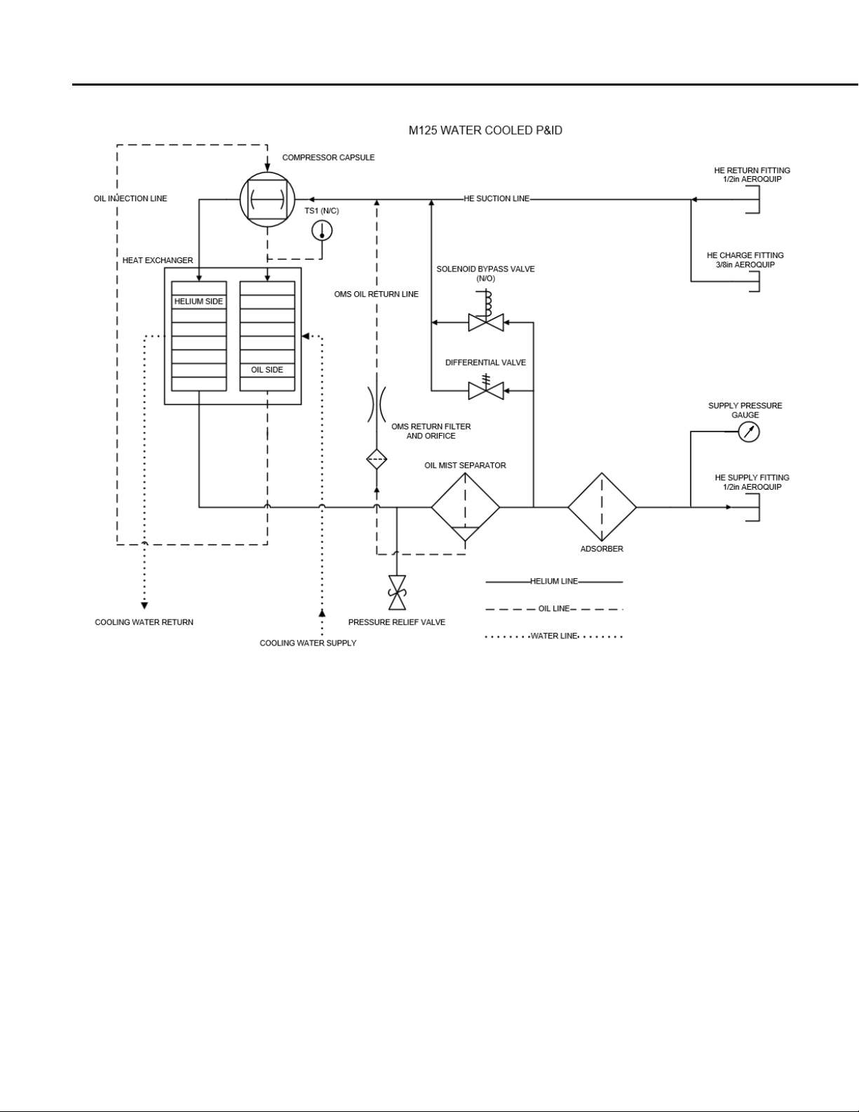
4.1.4 Operational Flow
The workflow of helium gas within the compressor follows these steps:
1. High-pressure helium gas is delivered from the compressor to the cold head through the "Supply" helium flex
line at 250-260 PSI (17.24 – 17.93 Bar).
2. The helium gas is then compressed during the compression stroke of the cryopump.
3. The cryopump then expands the helium gas to expand during its expansion stroke. During this cycle of
compression and expansion of the cryopump, the helium gas is forced through regeneration materials to
increase the thermodynamic efficiency of the cycle.
4. With each successive cycle, the regeneration material becomes colder and colder.
5. Eventually, the cryopump temperatures come down to cryogenic range.
6. After expansion, the helium gas returns to the compressor through the "Return" helium flex line at 50-100 PSI
(3.45 – 6.90 Bar) to begin the cycle again.
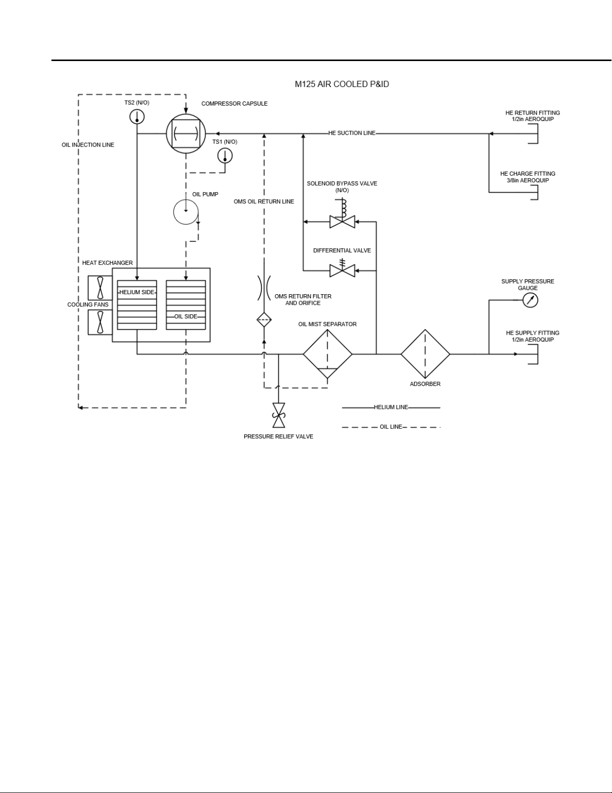
The helium flow between the Model 125 compressor’s components is illustrated in
Figure 1and Figure 2, for the water-cooled and air-cooled version of the Model 125 compressor, respectively.
User's Manual Rev B / February 2021 / M125 Helium Compressor
97-00020-000
6
Figure 1 – Flow Diagram for Water-Cooled Model 125 compressor
User's Manual Rev B / February 2021 / M125 Helium Compressor
97-00020-000
7
Figure 2 – Flow Diagram for Air-Cooled Model 125 compressor

User's Manual Rev B / February 2021 / M125 Helium Compressor
97-00020-000 8
4.2 Specifications
The Model 125 Helium Compressor specifications are listed in Table 4-2 and Table 4-3. Figure 3shows the Model 125
compressor dimensions.
Table 4-2: Power Requirements for Model 125 Compressor
P/N
Model
Voltage (AC)
Hz
Phase
Avg.
AMPs
Recommended
Circuit Breaker
91-00003-0LW
Model 125 Water-cooled
208/230
50/60
1
5-9
15
91-00003-1LA
Model 125 Air-cooled
208/230
50/60
1
6-10
15
Table 4-3: Model 125 Compressor Specifications
Feature/Component
Specification Description
Physical Dimensions
•Length 19.00 inches (483 mm)
•Height 16.00 inches (406 mm)
•
Width 19.50 inches (495 mm)
Weight
150 lb. (68 kg)
Helium Pressure
•Static: 190 ± 5 PSIG (13.1 ± .35 Bar)
•Operating: 250 ± 10 PSIG (17.24 ± .69 Bar) (supply)
Interface
•Cold head power connector mates with ASC and CTI drive
cables
•Compressor power cord is equipped with a Hubbell No.
5G66C plug
•
Helium connections: 1/2-inch Male Aeroquip couplings
Adsorber Replacement Schedule
15,000 Hours (per elapsed time meter on the compressor) or 3
years, whichever comes first
Cooling Water
•0.4 GPM (1.5 liters/min) minimum flow rate
•80°F (26.7°C) maximum inlet water temperature
•100°F (37.8°C) maximum outlet temperature
•Recommended chiller capacity: 1 ton/per unit
•
Water line connector: 3/8” Swagelok
Air Cooling
•
Air-cooled units must maintain a minimum clearance of at
least 12” (305 mm) at both the front and rear grills
•Maximum ambient temperature should not exceed 104°F
(40°C)

User's Manual Rev B / February 2021 / M125 Helium Compressor
97-00020-000 9
Figure 3 – Model 125 Dimensions
4.3 Ordering Information
Table 4-4 contains the ordering information for the Model 125 compressor unit. Customers can also order the optional
accessories and replacement parts listed in Table 4-5
Table 4-4: Model 125 Compressor Unit Ordering Information
Compressor Unit
Part Number
M125 Water-cooled, Low Voltage, Standard Drive Circuit
91-00003-0LW
M125 Air-cooled, Low Voltage, Standard Drive Circuit
91-00003-1LA
Table 4-5: Optional Accessories and Replacement Parts
Accessories/Replacement Parts
Part Number
Adsorber (Water-cooled model)
80034
Adsorber (Air-cooled model)
80111
Helium Lines (10ft.*)
10418-10
Helium Regulator
HR-580
Maintenance Manifold, for helium clean-up process on compressors and
cryopumps
10134
Cryopump Drive Cable (10ft.*), sends power to the cryopump motor from
the compressor
10144-10
Cryopump patch cable (3”), (onboard 10 pin to standard 6 pin)
81-00053-002
On-Board drive cable (10ft.*), sends power to the On-Board Cyropump
motor from the compressor
81-00005-006
*Custom length available.

User's Manual Rev B / February 2021 / M125 Helium Compressor
97-00020-000 10
5Installation
5.1 Safety Warnings
Review the safety warnings in Section 3before beginning any installation activities.
5.2 Installation Steps
5.2.1 Unpacking and Inspection
Once the equipment is received, inspect the exterior of the shipping carton for any signs of damage. Report any damage to
the shipping company immediately.
In addition, at least two “Tip-n-Tell” or “TiltWatch” labels are mounted on the exterior of the shipping carton. Inspect
these labels carefully before accepting the shipment. Any sign that the package has been mishandled during transit may
indicate that the compressor may be damaged due to oil migration within the system. This could cause the unit to
overheat and ultimately fail after a short period of operation. The compressor must be returned to the factory for service.
Report the mishandling of the package and file a damage claim with the shipping company immediately. Failure to do so
will void the warranty on the compressor. Please also contact Trillium US Inc. Technical Support using the contact
information found in Section 2.2.
Remove the straps and packaging materials on the compressor unit, then lift or roll the unit out of the carton carefully.
Inspect the exterior of the unit. If any damage is observed, inform the shipping company. Keep the original packaging
materials in case the unit needs to be returned to the factory for service or other reasons.
Most shipping companies have a certain grace period for reporting damages due to shipping in order to process the
insurance information in a timely manner. Therefore, it is highly recommended that shipping carton be opened and the
unit inspected whether or not it will be put into operation right away.
Caution: When transporting or storing the compressor unit, make certain it is not tilted by more than 45 degrees
to avoid the unit been tipped over.
5.2.2 Mounting the Compressor
It is highly recommended that the compressor unit be installed on a level and steady surface.
If the unit must be installed in a tilted manner, the maximum tilting angle is 10 degrees. Tilting the unit more than this
maximum allowable angle could result in damage and contamination in the system and may void the warranty on the unit.
5.2.3 Preparing the Compressor for Operation
1. Check the voltage of the power source before connecting the main power cable to a suitable connector or
disconnect box, making sure that the compressor switch is off.
2. For water-cooled Model 125 units, connect the cooling water:
a. Typical municipal drinking water is acceptable; however, a closed loop chilled water source is
recommended.
b. 0.4 to 0.5 GPM (1.5 – 1.9 liters/min) is required to achieve a maximum discharge temperature of 100°F
(38°C) (with 80°F (26.7°C) considered ideal)
c. Maximum inlet water pressure should not exceed 150 PSIG (10.3 Bar) (with less than 100 PSIG (6.9 Bar)
considered ideal).
3. For air-cooled Model 125 units, make sure the front and rear grills have at least 12” (305 mm) of clearance from
the nearest objects.
4. Verify that helium pressure is between 190 ± 5 PSIG (13.1 ± .35). If pressure is low, refer to Section 8.4.1 for
charging procedures.
5. Start the compressor and run for about 15 minutes to stabilize the compressor oil inventory.
6. The compressor is now ready to be connected to the cryopump.

User's Manual Rev B / February 2021 / M125 Helium Compressor
97-00020-000 11
5.2.4 Ambient Conditions and Coolant Connection
Ambient Conditions:
When the compressor is in operation, the ambient temperature should be between40°F to 104°F (5°C to 40°C). The
compressor unit should be set up in a non-condensing environment. An optimal location would be in a well ventilated (or
temperature controlled) location.
Coolant Connection:
Caution: For water-cooled compressor models, the water used in the unit operation must meet the
specifications indicated in Section 4.2.
Caution: Failure to comply with the coolant specifications may result in serious damage to the compressor and
may void the warranty on the unit.
Identify the inlet and outlet connection ports first before connecting the hoses. The water supply line should be connected
to the inlet port on the compressor.
Periodically check the coolant flow rate and temperature to ensure the proper operation of the compressor unit.
5.2.5 Connecting the Helium Flex lines
Caution: Attach or detach the helium flex lines only when the power to the compressor unit is switched off.
Never twist the helium flex lines during the installation process.
Before connecting the helium flex lines, follow these steps:
1. Identify the helium “Return” (low pressure) and “Supply” (high pressure) ports on the compressor front panel.
2. Clearly mark the helium flex line that will be used to connect to the corresponding “Supply” and “Return” port on
the cryopump or cold head,
Note: The helium flex lines are equipped with self-sealing couplings which can be attached and detached without helium
escaping.
Follow these steps to connect the helium flex lines:
1. Unscrew the protective caps from the couplings and keep the caps for future use.
2. Check the connectors for cleanness. When necessary, use lint-free clean cloth or soft brush to clean the
connectors.
3. Check the flat seals on the male couplings and make sure they are properly placed. Replace any missing or
defective seals.
4. Use only the open wrenches supplied with the installation kit. For a 1/2" coupling, tighten with a 1-3/16" wrench
and stabilize with a 1" wrench.
5. Tighten down all couplings as far as possible and then back off by one quarter turn to relieve strain.
If the flex lines need to be bent to a radius of less than 8" (203 mm), then a 90-degree helium elbow needs to be installed
(see Section 3.3 for the part number).

User's Manual Rev B / February 2021 / M125 Helium Compressor
97-00020-000 12
5.2.6 Filling the Compressor with Helium Gas
Caution: All safety regulations related to handling pressurized gas cylinders must be observed. Only use helium
with 99.999% or better purity when performing refill operation.
Follow these steps:
1. Connect a pressure reducer and a helium flex line to a helium supply gas cylinder
2. Connect the open end of the helium flex line to the helium gas charge/vent valve on the rear panel of the unit; do
not tighten the 1/4” flare connector on the end of the flex line
3. Open the valve at the cylinder
4. Set the pressure of the helium supply cylinder to the value specified in Table 4-3. Tighten the 1/4” flare connector
on the end of the helium flex line to the gas charge/vent valve of the compressor
5. Open the pressure regulator valve slightly so that the helium flex lines are purged with helium gas for at least 15
seconds.
6. Open the helium gas charge/vent valve and fill the compressor unit to the desired pressure value
7. Detach the coupling of the helium flex line from the helium charge/vent valve
8. Close the helium gas regulator on the supply cylinder
9. Seal the helium gas charge/vent valve on the compressor unit by properly securing with a protective cap.
5.2.7 Adjusting Helium Gas Pressure
Refer to Table 4-3 for the required pressure specification of the compressor unit. If the pressure falls below that level, the
helium gas refill procedure described in Section 5.2.6 needs to be performed. On the other hand, if the pressure is too high,
then the helium gas needs to be released in order to maintain the proper level.
Caution: If the compressor pressure drops over a period of time, either when not in operation or without the
lines being connected/disconnected, this may be an indication that there is a leak along the helium
circuit (i.e., compressor, lines or cold head/cryopump). If that is the case, do not just keep refilling the
system with helium gas. Such leaks will introduce ambient air/moisture and cause contamination in
the helium stream. This will result in catastrophic failure of the whole cryogenic system if not properly
addressed. Contact and report the leak to Trillium US Inc. immediately using the contact information
found in Section 2.2.

User's Manual Rev B / February 2021 / M125 Helium Compressor
97-00020-000 13
5.2.8 Electrical Connection
Caution: Before connecting power to the compressor unit, make sure the factory setting of the frequency switch
on the front panel matches the frequency of the power supply where the unit is being installed. Failure
to do so will result in performance degradation of the system.
Electrical connections are to be made in accordance with the diagram in Figure 4. Figure 5shows the Electrical Control
Chassis and the components within.
Figure 4 – Model 125 Electrical Schematic

User's Manual Rev B / February 2021 / M125 Helium Compressor
97-00020-000 14
Figure 5 – Model 125 Electrical Chassis Components (Inside View)
Table 5-1: Figure 5 Legend
Item
Description
Ref. Desig.
P/N
1
Capacitor, Run
C1
30016
2
Capacitor, Start
C2
30015
3
Capacitor, 60Hz
C3
30014
4
Capacitor, 50Hz
C4
30017
5
Fuse, 1 AMP (Not Shown)
F1,F2,F3,F4
50081
6
Fuse, 3 AMP (Not Shown)
F5,F6
31-00012-018
7
Relay, Start
K1
50085
8
Meter, Elapsed Time
ETM1
50089
9
Connector, 15 Pin Chassis
J1
50087
10
Connector, Housing, Mate-N-Lok
J2, J3
33-00138-000
11
Resistor, 150Ω, 100W
R1
30-00036-001
12
Resistor, 15Ω, 2W
R2
20056
13
Resistor, 68Ω, 1W
R3
30-00055-001
14
Switch, Compressor "ON-OFF"
SW1
50083
15
Switch, Safety Interlock
SW2
50155
16
Cold Head Power Transformer
T1
50082
17
24V Transformer
T2
31-00251-000
18
Terminal Block
TB1
50125

User's Manual Rev B / February 2021 / M125 Helium Compressor
97-00020-000 15
6Operations
6.1 Before Switching ON the System
After the compressor unit and its load (cryopump, cold head, etc.) are installed and connected, check the helium gas
pressure as indicated by the pressure gauge mounted on the rear panel of the compressor unit. Refer to Table 4-3, for the
proper static pressure readings for the compressor.
If the helium pressure needs to be adjusted, refer to Sections 8.4.1 and 8.4.2 for procedures to release helium gas in order
to reduce the pressure or to fill the compressor with more helium gas to increase the pressure.
Do not remove the top cover of the compressor unit. Doing so will disable the unit due to the built-in safety interlock
mechanism.
6.2 Normal Operation
The load of the compressor can be powered through the power connectors located on the front panel of the compressor.
To start operation of the compressor and its load, do the following:
1. Open the coolant supply (water-cooled compressor model only).
2. Switch on the main power source.
3. Press the ON button to start the compressor. Both the compressor and its load should start simultaneously.
During operation, check the coolant flow rate (water-cooled compressor) and the operating pressure frequently. Refer to
Table 4-3 for required coolant flow rate. If it is too slow, make sure any problems associated with water supply or water
outlet are resolved. Refer to Table 4-3 for proper helium pressure level for the compressor unit. If the helium pressure is
too low, switch off the compressor unit. It may be necessary to perform a helium "topping-up" maintenance procedure as
described in Section 8.4.1. If pressure drop-off happens frequently, there may be a substantial leak in the helium circuit of
the compressor. In this case, contact Trillium US Inc. customer service immediately (see Section 2.2).
To shut down the compressor unit, press the OFF button on the front panel. After that, allow coolant to continue to
circulate for at least 10 more minutes before shutting off flow.
7Troubleshooting
7.1 Troubleshooting Activities
Table 6-1 describes some problems that users might encounter while operating the Model 125 Cryopump Compressor and
provides solutions to those problems.
If a compressor problem still persists after performing the corrective actions described in this section, please contact
Trillium US Inc. Technical Support for further assistance (see Section 2.2).
Table 7-1: Trouble Shooting Procedures
Problem
Possible Cause
Corrective Action
The compressors On/Off
switch (SW1) remains in
the
On position when switched
on, but the pump does not
run.
1No power is coming from the power
source.
2Incorrect or disconnected wiring
within the compressor
1Check service fuses, circuit breakers,
and wiring associated with the power
source. Repair as needed.
2Check the compressor against the wiring
schematic. See Figure 5.
This manual suits for next models
2
Table of contents
Popular Air Compressor manuals by other brands


Gardner Denver
Gardner Denver L Series Operating and service manual

Sparmax
Sparmax ARISM mini user manual

Quincy Compressor
Quincy Compressor DEFENDER 7-2716 SCFH Installation, operation & maintenance manual

Corken
Corken D Series Installation, operation & maintenance manual

DENAIR
DENAIR DA Series Operation manual

Eagle
Eagle Portable Electric/Gas Compressor operating instructions


