Trimax Snake Parts list manual

1
SPARE PARTS
INSTRUCTIONS # 49
Date Created: 09/05/2017
Product: Snake
Title: Road Kit Option Fitment
SAFETY! Before attempting to make any adjustments or carry out maintenance on the mower, review
the hazard identification table (section 3a of your Operator Manual) and take all necessary precautions.
Collect the following parts:
2 x Mudguard Mounts
(410-000-247)
2 x Rolled Mudguards
(410-000-245)
2 x Mudguard Clamp Plated
(410-000-246)
8 x M8 x 25 Bolts
8 x M8 Nyloc Nuts
Position the Rolled Mudguards
(410-000-245) as shown.
Insert the M8 x 25 Bolts through the
Mudguard Mounts (410-000-247) and
the Rolled Mudguards
(410-000-245)
Note:
The orientation of the Guards must be
as shown to make a Left and Right-
Hand Assembly.
Position the Mudguard Clamp Plate
(410-000-246) as shown.
Secure with M8 Nyloc nuts.
Fully tighten.
Repeat for the second Mudguard.
Mudguard Mounts

2
Position the Guards as shown with the
LONG side of the Rolled Mudguards
facing you.
Note:
The orientation of the Guards MUST
be as shown, this will position the
LED Tail Lights in the correct
position.
Remove the Washers and Nuts fitted
to the LED Tail Lights (421-000-056)
Fit an LED Tail Light to each
Mudguard Mount as shown.
Refit the Flat Washers, Spring
Washers and Nuts to secure the LED
Tail Lights.
Tighten to secure.
Feed the LED Tail Light Wiring
through the holes shown.
Position the Right-Hand Mudguard
Assembly over the Right-Hand Tyre
on the Snake Chassis as shown.
Note:
See next picture for Bolt Setup detail.
LONG side of
Mudguards
LED Tail Lights in place
LED Tail Light Wiring
through here
Fasteners refitted
3
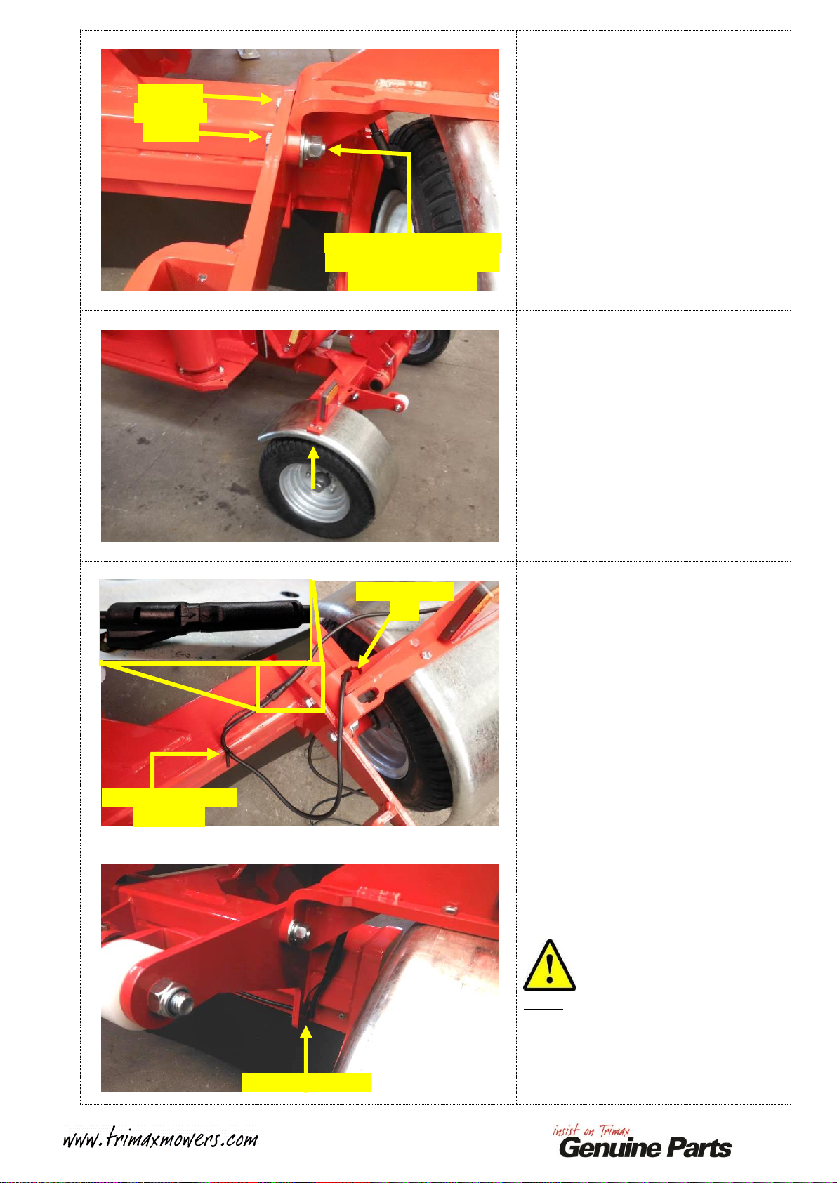
Insert two M12 x 40 Bolts with
MEDIUM STRENGTH THREAD
LOCKING COMPOUND applied
through the holes in the Chassis and
through the Mudguard Mount.
These are fitted from the INSIDE of
the Chassis.
Secure using M12 heavy flat washers,
M12 spring washers and M12 plain
nuts.
Fully tighten.
Repeat the above fitment to secure the
Left-Hand Mudguard Assembly to the
Snake Chassis.
The parts used are IDENTICAL.
Plug the Trailer Loom Ext. Cable
3.2m (421-000-055) into the
Right-Hand LED Light Cable.
Align the arrows to plug together.
Using a Cable Tie (210-900-010)
secure the Auxiliary Cable to the
Trailer Loom Ext. Cable.
Trim the tail off the Cable Tie.
Insert the Loom through the
Mudguard Mount (410-000-247)
Insert the Loom through the Rear
Roller Mount Plate as shown.
Note:
This is UNDERNEATH the Chassis
Rear Axle.
M12 x 40
Bolts from
this side
M12 Heavy Flat Washers,
Spring Washers and Plain
Nuts from this side
Loom through
here
Cable Tie Auxiliary
Cable here
Loom through here
4
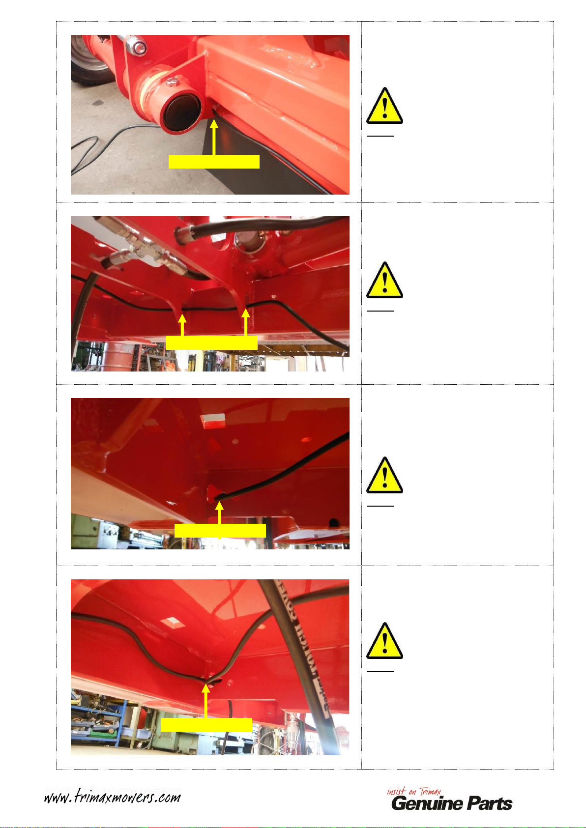
Insert the Loom through the Rear
Outrigger Mount Plate as shown.
Note:
This is UNDERNEATH the Chassis
Rear Axle.
Insert the Loom through the Front and
Rear Lift Frame Plates.
Note:
This is UNDERNEATH the Left and
Right-Hand Hydraulic Rams.
Insert the Loom through the hole in
the Left-Hand side of the Gearbox
Mount Plate.
Note:
This is UNDERNEATH the Chassis
4-Way Gearbox.
Repeat the above for the Left-Hand
LED Tail Light Loom.
Note:
The parts used are IDENTICAL.
The Cable Routing is IDENTICAL,
just fitted to the other side of the
Chassis.
Loom through here
Loom through here
Loom through here
Loom through here
5
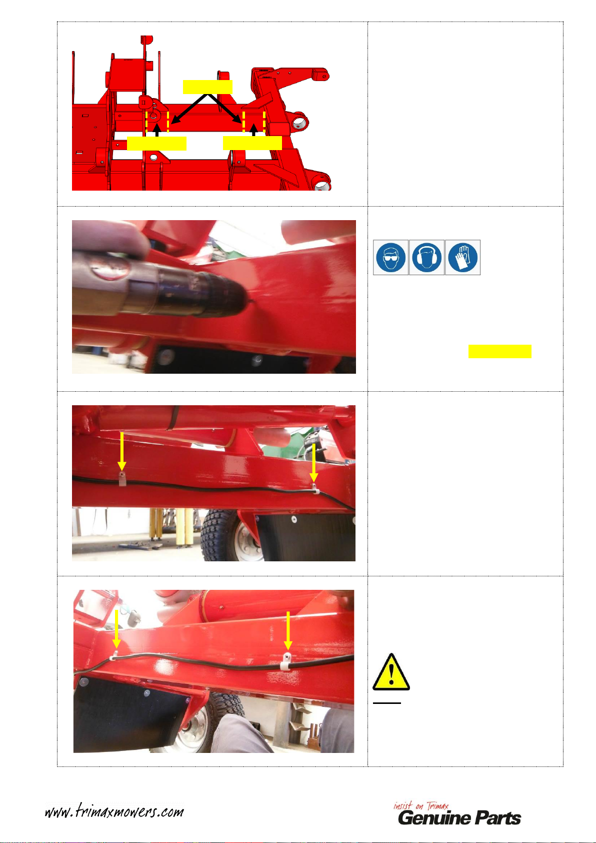
Mark out the two positions shown on
the Right-Hand Chassis Rail.
These will need to be drilled to rivet
the P-Clips in place to secure the
Loom.
Each position is central between the
TOP and Bottom of the Chassis Rail.
Repeat this step for the other side.
Once marked out as detailed above,
Centre Punch ALL four marks and
drill through the INSIDE surface of
each Chassis Rail.
Drill bit required: 4mm / 3/16”
Secure the Right-Hand Loom with
two P-Clips (210-900-008) and two
5-5 Rivets (213-443-260) fitted into
the drilled holes.
Repeat the above for the Left-Hand
Loom.
Note:
The parts used are IDENTICAL.
100mm / 4”
100mm / 4”
Mark here

6
Pull all excess Loom through towards
the FRONT of the Chassis.
Using two Cable Ties (210-900-010)
secure the Looms to the REAR of the
4-Way Gearbox Mount as shown.
Trim the tails off the Cable Ties.
Note:
This is UNDERNEATH the Chassis
4-Way Gearbox.
Using a Cable Tie (210-900-010)
secure the Looms together as shown.
Trim the tail off the Cable Tie.
Note:
This is UNDERNEATH the Chassis
4-Way Gearbox.
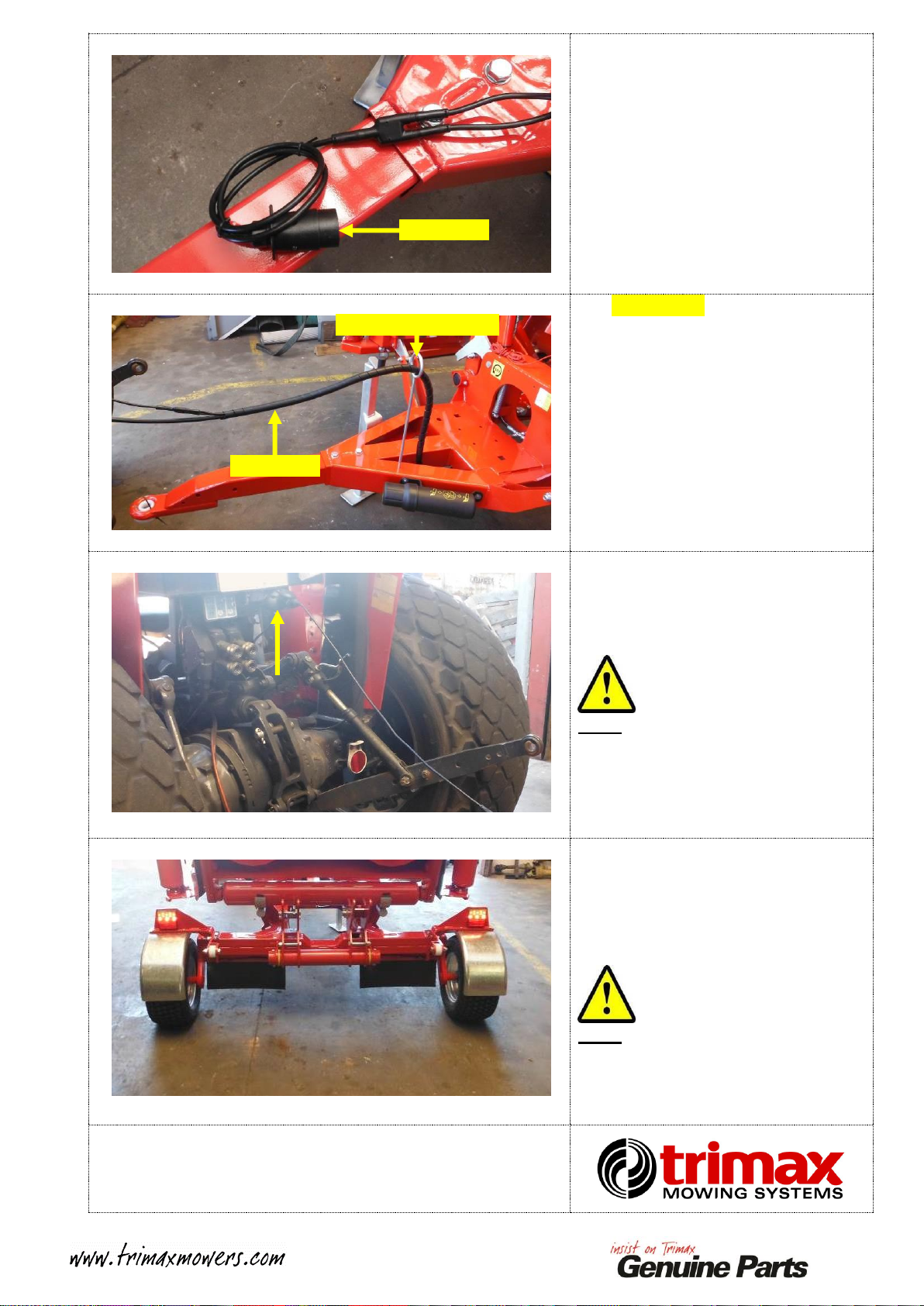
Collect the Trailer Loom
Y-Connector (421-000-054)
Note:
The connector has R and L marked on
it, this determines where the two
Loom Cables attach to.
Connect the Y-connector
(421-000-054) to both the Loom
Cables.
Note:
Ensure the RH Guard is connected to
the Ron the Y-connector!
Ensure the LH Guard is connected to
the L on the Y-connector!
L
R
R
L
7
Align the arrows and attach the
Trailer Plug Inc. 1m Cable
(421-000-053) to the Y-connector
(421-000-054)
Use 1.3m/ 4’ 1/4" of Spiral Wrap
(450-900-014) secure the Looms and
Main Hydraulic Hose together.
Start the Spiral Wrap from just under
the 4-Way Gearbox Mount Plate
(418-000-484) to the Y-Connector
(421-000-05)
Feed this Bundle through the Rope
and Hose Guide attached to the
FRONT of the Chassis A-Frame.
Connect the Trailer Plug Inc. 1m
Cable (421-000-053) to the Tractor.
Note:
A 7-pin Round Plug or Adaptor is
required.
Test the following functions:
-Indicator Left
-Indicator Right
-Tail Lights
-Brake Lights
Note:
If the Indicators work opposite to
what is intended, swap the two cables
that run to the Y connector!
This process is now complete.
Trailer Plug
Rope and Hose Guide
Spiral Wrap
Other manuals for Snake
1
Table of contents


