RVR Solar VJ10000-TR User manual

Date: 25/07/03 R.V.R. Elettronica S.r.l. (BO) VJ10000-TR - R.F. Tube Amplifier
1
TECHNICAL AND MANTEINANCE MANUAL
VJ10000-TR
10KW Power Triode Amplifier 87.5-108 MHz

Date: 25/07/03 R.V.R. Elettronica S.r.l. (BO) VJ10000-TR - R.F. Tube Amplifier
2
Manufactured by R.V.R. Elettronica - Italy

Date: 25/07/03 R.V.R. Elettronica S.r.l. (BO) VJ10000-TR - R.F. Tube Amplifier
3
INDEX
I - PRELIMINARY INSTRUCTIONS AND WARRANTY INFORMATION.......................................................... 6
II - TUBE WARRANTY INSTRUCTIONS................................................................................................................... 8
VARIAN POWER GRID PRODUCT LIMITED WARRANTY..................................................................................8
III – SAFETY REGULAMENT! .................................................................................................................................... 9
WARNING! ................................................................................................................................................................. 9
TREATMET OF ELECTRICAL SHOCK ................................................................................................................... 10
FIRST-AID................................................................................................................................................................... 12
TREATMENT OF ENECTRICAL BURNS................................................................................................................ 12
NOTE........................................................................................................................................................................ 12
CHAPTER 1.................................................................................................................................................................... 13
VJ10000-TR GENERAL DESCRIPTION................................................................................................................... 13
1.1 MECHANICAL DESCRIPTION ................................................................................................................... 13
1.2 ELECTRICAL DESCRIPTION ..................................................................................................................... 13
1.3 TECHNICAL SPECIFICATIONS ................................................................................................................. 13
CHAPTER 2.................................................................................................................................................................... 14
ELECTRICAL DESCRIPTION................................................................................................................................... 14
2.1 INTRODUCTION ......................................................................................................................................... 14
CHAPTER 3.................................................................................................................................................................... 33
EQUIPMENT INSTALLATION ................................................................................................................................. 33
3.1 INTRODUCTION ......................................................................................................................................... 33
3.2 UNPACKING................................................................................................................................................ 33
3.3 TUBE INSTALLATION................................................................................................................................. 35
3.4 EQUIPMENT SETTING AT WORK ............................................................................................................. 44
CHAPTER 4.................................................................................................................................................................... 46
TUBE MEASURES CARD CALIBRATION ............................................................................................................. 46
4.1 NOTICE ........................................................................................................................................................ 46
4.2 INTRODUCTION ......................................................................................................................................... 46
4.3 MEASURES CARD ADJUSTING OPERATIONS ........................................................................................ 50
CHAPTER 5.................................................................................................................................................................... 60
MAINTENANCE......................................................................................................................................................... 60
5.1 SAFETY RULES............................................................................................................................................ 60
MAINTENANCE FIRST LEVEL ............................................................................................................................... 60
5.2 SAFETY RULES............................................................................................................................................ 60
MAINTENANCE SECOND LEVEL .......................................................................................................................... 60
5.3 MODULES REPLACING ............................................................................................................................. 60
5.4 TUBE REPLACING...................................................................................................................................... 61
5.5 AIR FILTER REPLACING............................................................................................................................ 61
CHAPTER 6.................................................................................................................................................................... 62
ADJUSTMENTS.......................................................................................................................................................... 62
6.1 FREQUENCY CHANGE .............................................................................................................................. 62
APPENDIX A.................................................................................................................................................................. 62
CIRCUIT DIAGRAMS AND LAYOUTS................................................................................................................... 62

Date: 25/07/03 R.V.R. Elettronica S.r.l. (BO) VJ10000-TR - R.F. Tube Amplifier
4
PICTURES
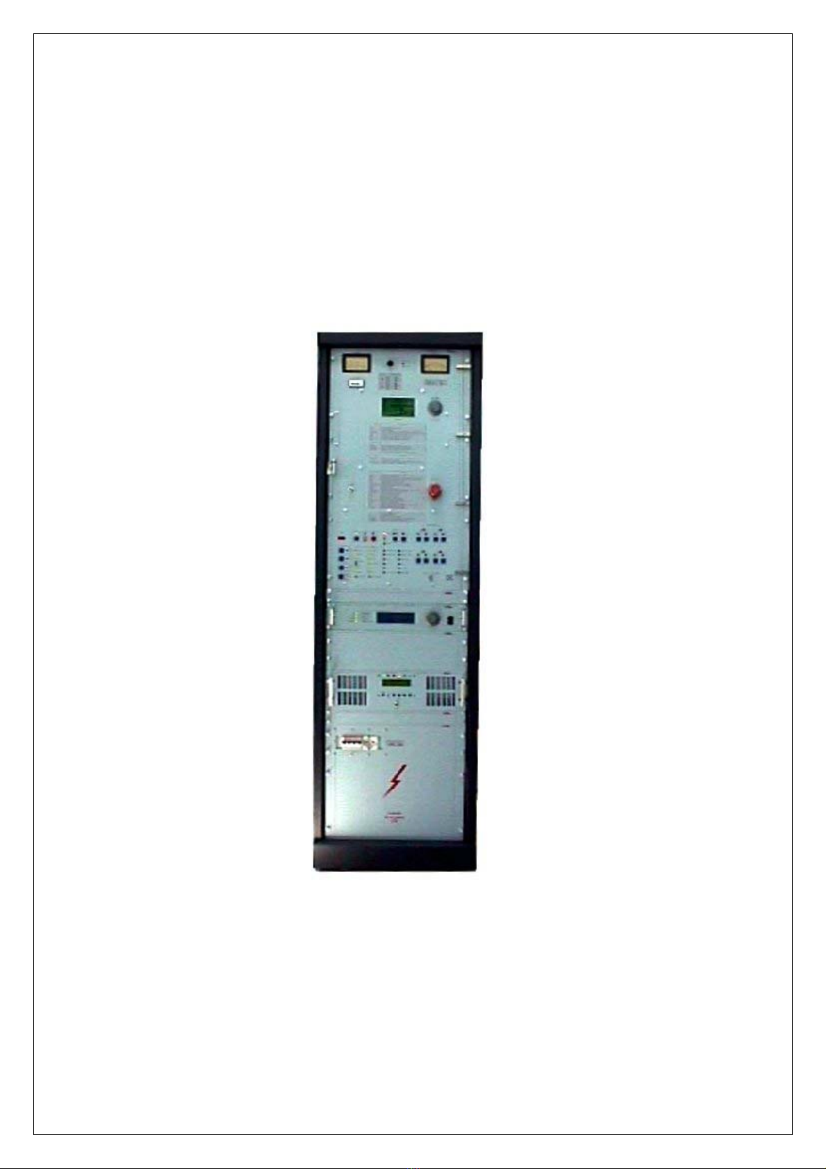
FIG. 1 FRONTAL VIEW ........................................................................................................................................... 15
FIG. 2 REAR VIEW ................................................................................................................................................... 16
FIG. 3 UPPER VIEW ................................................................................................................................................. 17
FIG. 4 HINGED FRONTAL PANEL WITH TELEMETRY..................................................................................... 18
FIG. 5 HINGED FRONTAL PANEL WITHOUT TELEMETRY ............................................................................ 20
FIG. 6 HIGH VOLTAGE PANEL.............................................................................................................................. 21
FIG. 7 P1 POWER SUPPLY SECTION VIEW......................................................................................................... 22
FIG. 8 P2 POWER SUPPLY SECTION VIEW......................................................................................................... 23
FIG. 9 R.F. CAVITY FRONTAL VIEW ................................................................................................................... 25
FIG. 10 R.F. CAVITY FRONTAL VIEW................................................................................................................ 27
FIG. 11 TUNING MOTORIZED MECHANISM VIEW.........................................................................................28
FIG. 12 R.F. CAVITY TOP VIEW .......................................................................................................................... 29
FIG. 13 R.F. CAVITY LEFT LATERAL VIEW ..................................................................................................... 30
FIG. 14 R.F. CAVITY RIGHT LATERAL VIEW................................................................................................... 31
FIG. 15 REAR VIEW ............................................................................................................................................... 32
FIG. 16 TUBE INSTALLATION DIAGRAM N°1 ................................................................................................. 36
FIG. 17 TUBE INSTALLATION DIAGRAM N°2 ................................................................................................ 37
FIG. 18 TUBE INSTALLATION REFERENCE VIEW N°2 .................................................................................. 38
FIG. 19 TUBE INSTALLATION DIAGRAM N°3 ................................................................................................ 39
FIG. 20 TUBE INSTALLATION REFERENCE VIEW N°3 ................................................................................. 40
FIG. 21 TUBE INSTALLATION REFERENCE VIEW N°4 ................................................................................. 41
FIG. 22 TUBE INSTALLATION REFERENCE VIEW N°4 ................................................................................. 42
FIG. 23 REGOLAZIONE RF - MHZ ........................................................................................................................ 43
FIG. 24 MEASURES CARD REFERENCE VIEW................................................................................................ 47
FIG. 25 MEASURES CARD REPLACING DIAGRAM N°1 ................................................................................. 48
FIG. 26 MEASURES CARD REPLACING DIAGRAM N°2 ................................................................................. 49
FIG. 27 POWER SUPPLIES CONNECTION FOR THE CALIBRATION OF TEST POINT VOLTAGES......... 53
FIG. 28 REPORT MEASURE................................................................................................................................... 58
FIG. 29 POWER SUPPLY SOCKET........................................................................................................................ 63
FIG. 30 ANODE TENSION TRANSFORMER SOCKET ....................................................................................... 64
FIG. 31 RACK POWER SUPPLY BASE ................................................................................................................. 65
FIG. 32 HIGH TENSION PANEL ............................................................................................................................ 66
FIG. 33 ELECTROMECHANICAL PLANE (TRIODE)......................................................................................... 67
FIG. 34 RESISTENZE DI SOFT-START E POLARIZZAZIONE VALVOLA ...................................................... 70
FIG. 35 TUBE AMPLIFIERS PROTECTIONS CARD............................................................................................ 71
FIG. 36 HIGH POWER RELAYS CARD................................................................................................................. 72
FIG. 37 TUNING RELAYS CARD .......................................................................................................................... 73
FIG. 38 TELEMETRY INTERFACE CARD............................................................................................................ 74
FIG. 39 MEASURES CALIBRATION CARD......................................................................................................... 75
FIG. 40 THERMAL STROBE CONNECTOR ......................................................................................................... 76
FIG. 41 P.W.R. MEASURE CONNECTOR ............................................................................................................. 77
FIG. 42 I2 CBUS CONNECTOR FOR TELEMETRY BOX ................................................................................... 78
FIG. 43 PTXLCD CONNECTOR ............................................................................................................................. 79
FIG. 44 LOW VOLTAGE CIRCUIT DIAGRAM .................................................................................................... 80
FIG. 45 THREE-PHASES CIRCUIT DIAGRAM .................................................................................................... 81
FIG. 46 MEASURES AND ALLARMS CIRCUIT DIAGRAM............................................................................... 82
FIG. 47 ELECTRIC SCHEMES................................................................................................................................ 83
TABLES
TABLE A - ELECTRICAL SPECIFICATIONS ............................................................................................................. 13
TABLE B - MECHANICAL AND ENVIROMENTAL SPECIFICATIONS ................................................................. 14
TABLE C - RIFERIMENTO FREQUENZE .................................................................................................................. 43

Date: 25/07/03 R.V.R. Elettronica S.r.l. (BO) VJ10000-TR - R.F. Tube Amplifier
5
TABLE D - MEASURE TESTS CARD .......................................................................................................................... 54
TABLE E - QUIESCENT WORKING PARAMETERS................................................................................................. 59
TABLE F - ADVISABLE EQUIPMENT FOR TEST ..................................................................................................... 59
TABLE G - VOLTAGE STABILYZER PARAMETERS............................................................................................... 59

Date: 25/07/03 R.V.R. Elettronica S.r.l. (BO) VJ10000-TR - R.F. Tube Amplifier
6
I - PRELIMINARY INSTRUCTIONS AND WARRANTY
INFORMATION
Please observe safety precautions when handling this unit. This equipment contains
dangerous currents and high voltages.
This manual is written as a general guide for those having previous knowledge and
experience with this kind of equipment. It is not intended to contain a complete statement of
all safety warnings which should be observed by personnel in using this or other elettronic
equipment.
R.V.R. doesn't assume responsability for injury or damage resulting from improper
procedures or practices by untrained/unqualified personnel in the handling of this unit.
Please observe all local codes and fire protection standards in the operations of this unit.
CAUTION: always disconnect power before opening covers or removing any part of this
unit. Use appropriate grounding procedures to short out capacitors and high voltage points
before servicing.
Any damage to the goods must be reported to the carrier in writing on the shipment receipt.
Any discrepancy or damage discovered subsequent to delivery, shall be reported to R.V.R.
within five (5) days from its receipt.
R.V.R. extends to the original end-user purchaser all original manufacturers warranties
which are transferable and all claims are to be made directly to R.V.R. per indicated
procedures.
All manufacturers warranties will be supported by R.V.R. to ensure precise and speedy
service where possible.
R.V.R. shall not be liable for any damage of whatsoever nature, arising out of or in
connection with the product or its use thereof.
R.V.R.'s warranty shall not include:
a. Re-shipment of the unit to R.V.R. for repair purposes
b. Any unauthorized repair/modification
c. Incidental/consequential damages as a result of any defect
d. Nominal non-incidental defects
e. Re-shipment costs or insurance of the unit or replacement
units/parts
Warranty shall come into force from invoice date and for the period of the manufactures
warranty.

Date: 25/07/03 R.V.R. Elettronica S.r.l. (BO) VJ10000-TR - R.F. Tube Amplifier
7
To claim your rights under this warranty:
a. Contact the dealer or distributor where you prchased the unit. Describe the problem
and ask if he has an easy solution. Dealers and Distributors are supplied with all the
information about problems that may occur and usually they can repair the unit quicker than
what the manufacturer could do. Very often installing errors are discovered by dealers.
b. If your dealer cannot help you, contact R.V.R. in Bologna and explain the problem.
If it is decided to return the unit to the factory, R.V.R. will mail you a regular authorization
with all the necessary instructions to send back the goods.
c. When you receive the authorization, you can return the unit. Pack it carefully for the
shipment, preferably using the original packing and seal the package perfectly. The
customer always assumes the risks of loss(i.e., R.V.R. is never responsible for damage or
loss), untill the package reaches R.V.R. premises. For this reason, we suggest you to insure
the goods for the whole value. Shipment must be effected C.I.F. (PREPAID) to the address
specified by R.V.R.'s service manager on the authorization.
DO NOT RETURN UNITS WITHOUT OUR AUTHORIZATION AS THEY WILL BE
REFUSED.
Be sure to enclose a written technical report where mention all the problems found and a
copy of your original invoice establishing the starting date of the warranty.
Replacement and warranty parts may be order from the following address. Be sure to
include the equipment model and serial number as well as part description and part number.
R.V.R. Elettronica S.p.a. - Broadcasting Equipment -
Via del Fonditore, 2/2c
Zona Roveri
40138 Bologna - Italy
International Phone: +39 - 51 - 6010506
FAX Number: +39 - 51 - 6011104
R.V.R. reserves the right to modify the design and specifications of the equipment in this
manual without previous

Date: 25/07/03 R.V.R. Elettronica S.r.l. (BO) VJ10000-TR - R.F. Tube Amplifier
8
II - TUBE WARRANTY INSTRUCTIONS
VARIAN POWER GRID PRODUCT LIMITED WARRANTY
Varian products are warranted to be free from defects in workmanship and materials only.
The warranty involves both calendar time and filament (or heather) operation time.
Specifically involved are: time since the product was shipped from varian time since
delivery to the user, and operation time.
WHICHEVER ELAPSES FIRST CONCLUDES THE WARRANTY.
The warranties are determined by the codes shown in the price schedule.
TIME SINCE TIME SINCE TIME SINCE
SHIPMENT SHIPMENT HEATER-ON
Code from EIMAC To The User Time
T 36 MONTHS 24 MONTHS 10.000 HOURS
R 24 MONTHS 12 MONTHS 5.000 HOURS
P 24 MONTHS 12 MONTHS 4.000 HOURS
N 24 MONTHS 12 MONTHS 3.000 HOURS
K 24 MONTHS 12 MONTHS 1.000 HOURS
L LIFE TESTED AT FACTORY IN LIEU OF AN OTHER WARRANTY
12 24 MONTHS 12 MONTHS
The last category is for hardware or accessory items whwre only calendar time is involved.
An Original Equipment Manufacturer (OEM) or an authorized Varian Distributor can hold
an item in his stock for 12 months and the end user still receiver full warranty. As an
example, warranty code T is for 36 months from the date of the shipment from EIMAC, or
24 months from the date of delivery to the user,or 10.000 hours of filament-on time,
whichever elapses first.
A product which fails (because of faulty workmanship or materials) in the first 10% of the
warranty-time hours will be heither replaced at no charge by Varian or 100% of the
purchase price will be credited through the original authorized Varian Distributor or OEM.
If a failure occurs in the remaining 10-100% of the warranty time hours a prorated
adjustment will be calculated and credit issued. This can only be done through the original
OEM or authorized Varian Distributor
A prorated credit is calculated as follows:
Warranty (hours) - Use Time (hours)
= % Credit
Warranty (hours)

Date: 25/07/03 R.V.R. Elettronica S.r.l. (BO) VJ10000-TR - R.F. Tube Amplifier
9
Thus for failure Code N (3000 hours) if failure occurred after 600 hours and was found to be
workmanship or materials related:
3000 - 600
= 80%
3000
Tubes being returned on a warranty claim are normally sent to authorized Varian distributor
or OEM from whom originally purchased. If returned directly to the Varian plant of
manufacture, the authorized Varian Distributor or OEM from whom purchased should be
notified in case there are some special instructions.
All products returned on a warranty claim must be shipped via prepaid freight and include a
completed copy of a service report form, a copy of which is included with every shipped
product. A warranty claim cannot be processed without this form. A copy of the original
invoice, bill of sale, or other purchase document should be included with the executed
service report form to establish purchase date and price.
The original Varian shipping carton and packing material should always be used for any
warranty claim return. Shipping damage because of poor packing will normally preclude
any warranty adjustment since the damage will usually make any testing or measuraments
impossible.
PARCEL POST SHOULD NEVER BE USED FOR SHIPMENT OF TUBES.
III – SAFETY REGULAMENT!
WARNING!
The currents and voltages in this equipment are dangerous! Personnel must at all times
observe safety regulation!.
This manual is intended as a general guide for trained and qualified personnel who are
aware of the dangers inherent in handling potentially hazardous electrical and electronic
circuits.
It is not intended to contain a complete statement of all safety precautions which should be
observed by personnel in using this or other electronic equipment.
The installation, operation, maintenance and service of this equipment involves risks both to
personnel and equipment, and must be performed only by qualified personnel exercising due
care. R.V.R. ELETTRONICA s.p.a. shall not be responsible for injury or damage resulting
from improper procedures or from the use of improperly trained or inexperienced personnel
performing such tasks.
During installation and operation of this equipment, local building codes and fire protection
standards must be observed.
WARNING!
Always disconnect power before opening covers, doors, enclosures, gates, panels or
shields. Always use grounding sticks and short out high voltage points before servicing.
never make internal adjustments, perform maintenance or service when alone or when
fatigued.
Do not remove, short-circuit or tamper with interlock switches on access covers, doors,
enclosures, gates, panels or shields.
Keep away from live circuits, know your equipment and don't take chances.
WARNING!

Date: 25/07/03 R.V.R. Elettronica S.r.l. (BO) VJ10000-TR - R.F. Tube Amplifier
10
In case of emergency ensure that power has been disconnected.
TREATMET OF ELECTRICAL SHOCK
1) If victim is not responsive follow the A-B-C's of basic life support.
PLACE VICTIM FLAT ON HIS BACK ON A HARD SURFACE
A) AIRWAY B) BREATHING
NOTE: DO NOT INTERRUPT RHYTHM OF COMPRESSION WHEN SECOND
PERSON IS GIVING BREATH.
Call for medical assistance as soon as possible.
2) If victim is responsive:
a. Keep them warm.
b. Keep them as quiet as possible.
IF PULSE ABSENT, BEGIN
ARTIFICIAL CIRCULATION APPROX. 80 SEC. : ONE RESCUER, 15 COMPRESSIONS,
2 QUICK BREATHS.
APPROX. 60 SEC. : TWO RESCUERS, 5 COMPRESSIONS,
1 BREATH
LIFT UP NECK, PUSH,
FOREHEAD BACK,
CLEAR OUT MOUTH IF
N
ECESSARY, OBSERVE
FOR BREATHING.
TILT HEAD PINCH NOSTRILS,
MAKE AIRTIGHT SEAL, 4 QUICK
FULL BREATHS. REMEMBER
MOUTH TO MOUTH
RESUSCITATION MUST BE
COMMENCED AS SOON AS
POSSIBLE.
IF NOT BREATHING, BEGIN
ARTIFICIAL BREATHING
IF UNCONSCIOUS,
OPEN AIRWAY
C) CIRCULATION
CHECK CAROTID PULSE DEPRESS STERNUM 1 1/2" TO 2"

Date: 25/07/03 R.V.R. Elettronica S.r.l. (BO) VJ10000-TR - R.F. Tube Amplifier
11
c. Loosen their clothing (a reclining position is recommended).

Date: 25/07/03 R.V.R. Elettronica S.r.l. (BO) VJ10000-TR - R.F. Tube Amplifier
12
FIRST-AID
Personnel engaged in the installation, operation, maintenance or servicing of this equipment
are urged to become familiar with first-aid theory and practices. The following information
is not intended to be a complete first-aid procedure, it is brief and is only to be used as a
reference. It is the duty of all personnel using the equipment to be prepared to give adequate
Emergency First Aid and thereby prevent avoidable loss of life.
TREATMENT OF ENECTRICAL BURNS
1) Extensive burned and broken skin.
a. Cover area with clean sheet or cloth.
(Cleanest available cloth article).
b. Do not break blisters, remove tissue, remove adhered particles of clothing, or apply
any salve or ointment.
c. Treat victim for shock as required.
d. Arrange transportation to a hospital as quickly as possible
e. If arms or legs are affected keep them elevated.
NOTE
If medical help will not be available within an hour and the victim is conscious and not
vomiting, give him a weak solution of salt and soda: 1 level teaspoonful of salt and 1/2 level
teaspoonful of baking soda to each quart of water (neither hot or cold). Allow victim to sip
slowly about 4 ounces (half a glass) over a period of 15 minutes. Discontinue fluid if
vomiting occurs (Do not give alcohol).
2) Less severe burns - (1st & 2nd degree)
a. Apply cool (not ice cold) compresses using the cleanest available cloth article.
b. Do not break blisters, remove tissue, remove adhered particles of clothing, or apply
salve or ointment.
c. Apply clean dry dressing if necessary.
d. Treat victim for shock as required.
e. Arrange transportation to a hospital as quickly as possible.
f. If arms or legs are affected keep them elevated.

Date: 25/07/03 R.V.R. Elettronica S.r.l. (BO) VJ10000-TR - R.F. Tube Amplifier
13
CHAPTER 1
VJ10000-TR GENERAL DESCRIPTION
1.1 MECHANICAL DESCRIPTION
The VJ10000-TR is allocated in a 19" rack, 40H, 7 of which are free and can be used to
insert an exciter, a receiver or any other equipment. Two analog instruments are placed on
the hinged frontal panel (FIG. 1) with all other controls and commands.
The rear panel (FIG. 2) hasn’t any connectors but only the air input for the cooling blower,
completed with the air filter and the hole for power supply and external exciters cables.
A chimney is placed on top section of the rack (FIG. 3) that allows to push out hot air. The
antenna connector is placed on the top part too. The type of connector for the ouput is 1"+
5/8 or 3” 1/8 (optional).
1.2 ELECTRICAL DESCRIPTION
The VJ10000-TR is a tube amplifier, with grounded grid configuration, working on the
frequency range 87.5-108 MHz.
This amplifier is able to operate at 10KW output power with a driving power of about 500
W. The amplifier has motorized plate, load and input tuning, and is able to cover the
completely frequency range. The VJ10000-TR is been projected to use a three-phases mains
voltage (monphase only on request).
1.3 TECHNICAL SPECIFICATIONS
See as reference the Table A for electrical specifications and Table B for mechanical and
enviromental specifications.
TABLE A - ELECTRICAL SPECIFICATIONS
Alternate mains voltage Three phases: 220-240V ±15%, 50-60 Hz
380-415V ±15%, 50-60 Hz
Mono phase: 220-240V ±15%, 50-60 Hz
Frequency Range 87.5 - 108 MHz
(other on request)
Output Power 11000 W max, 10000 W typical
RF Output Impedance EIA 1+5/8" connector, 50 Ohm
RF Input Impedance N-type connector, 50 Ohm
RF Driving Power 500 W max
Tube EIMAC 3CX15000A7
Cooling Forced air cooling
Spurious and harmonics suppression Exceed or equal to FCC an CCIR requirements
Power consumption about 18-20 KW

Date: 25/07/03 R.V.R. Elettronica S.r.l. (BO) VJ10000-TR - R.F. Tube Amplifier
14
TABLE B - MECHANICAL AND ENVIROMENTAL SPECIFICATIONS
40 HE Rack Dimension 565 mm (22.24") W
850 mm (33.46") D
1894 mm (74.56") H
Panel Dimension 483 mm (19") W
1779 mm (71.11") H
Weight 470 Kg (770 Lbs)
Working extreme temperatures from -10° to +50°C
Umidity max 90%, Without condensing
CHAPTER 2
ELECTRICAL DESCRIPTION
2.1 INTRODUCTION
This chapter describes accurately the VJ10000-TR electrical components.
For an easy understanding, the equipment is been divided in modules, each of them is
described completely as follows.

Date: 25/07/03 R.V.R. Elettronica S.r.l. (BO) VJ10000-TR - R.F. Tube Amplifier
15
FIG. 1 FRONTAL VIEW
REF. DESCRIPTION
1) Protections panel (18U)
2) Exciter (2U)
3) Driver (3H)
4) High Voltage Panel (9H)
5) Free panel (1HE)
6) Free panel (3HE )
7) Free panel (2HE)
8) Free panel (2HE)

Date: 25/07/03 R.V.R. Elettronica S.r.l. (BO) VJ10000-TR - R.F. Tube Amplifier
16
FIG. 2 REAR VIEW
REF. DESCRIPTION
1) Rear panel
2) Air filter

Date: 25/07/03 R.V.R. Elettronica S.r.l. (BO) VJ10000-TR - R.F. Tube Amplifier
17
FIG. 3 UPPER VIEW
REF. DESCRIPTION
1) RF output connector (1+5/8")
2) Output air chimney (200 mm)
3) Upper panel

Date: 25/07/03 R.V.R. Elettronica S.r.l. (BO) VJ10000-TR - R.F. Tube Amplifier
18
FIG. 4 HINGED FRONTAL PANEL WITH TELEMETRY

Date: 25/07/03 R.V.R. Elettronica S.r.l. (BO) VJ10000-TR - R.F. Tube Amplifier
19
REF. DESCRIPTION
1) MULTIMETER: Analog instrument for the measures of temperature,
filament voltage and current, anode voltage and current
and grid voltage.
2) VOLTAGES SELECTOR: Voltages selector for the measures of the following.
3) FWD/REF SELECTOR: Selector for forward / reflected power measure.
4) POWER INSTRUMENT: Analog instrument for the measure of the forward and
reflected power
5) INSTRUMENT RESET: Mechanical reset of analog instrument for the
measure of the forward and reflected power.
6) ENCODER: Encoder for telemetry connection (optional).
7) ENCODER SWITCH: Key switch to enable the telemetry (optional).
8) EMERGENCY PUSH SWITCH: Emergency push switch to stop the equipment.
9) TUNING KEY SWITCH: Key switch to enable the motorized tuning.
10) TIME FILAMENT DISPLAY: Display for the screening of the pre-heating
filament time.
11) R.F. SAMPLE: Connector for R.F. signal test.
12) HANDLE: Handle to open the hinged panel
13) DISPLAY: Display for the screening of the equipment and
telemetry parameters (optional).
14) HOURS COUNTER: Equipment working hours counter
15) VOLTAGES RESET: Mechanical reset of analog instrument.

Date: 25/07/03 R.V.R. Elettronica S.r.l. (BO) VJ10000-TR - R.F. Tube Amplifier
20
FIG. 5 HINGED FRONTAL PANEL WITHOUT TELEMETRY
Table of contents
Other RVR Solar Amplifier manuals