Trinity Amps TRIP TOP User manual

TrinityAmps Trip Top Builders Guide Ver1.9.docx
- 1 -
The Trinity Amps
TRIP TOP
Excerpts from the Trip Top Builder's Guide
DO NOT USE FOR BU LDS
For the sole personal use of Trinity Amps Customers.
August 2017, Version 1.96
Parts Trinity Amps 2005 - 2017
www.trinityamps.com

TrinityAmps Trip Top Builders Guide Ver1.9.docx
Page - 2 -

TrinityAmps Trip Top Builders Guide Ver1.9.docx
Page - 3 -

TrinityAmps Trip Top Builders Guide Ver1.9.docx
Page - 4 -
Table of Contents
Table of Contents ............................................................................................................................................................................ 4
Introduction ...................................................................................................................................................................................... 7
Acknowledgements .......................................................................................................................................................................... 7
WARNING ...................................................................................................................................................................................... 8
Please Read this Information Carefully ...............................................................................................................................8
Version Control .............................................................................................................................................................................. 10
Trip Top Description .................................................................................................................................................................... 12
Guitar Amplifier Basics ................................................................................................................................................................. 14
Distortion ................................................................................................................................................................................... 15
General Amplifier Operation ....................................................................................................................................................... 17
Some DO NOTS ...................................................................................................................................................................... 17
Some DOs .................................................................................................................................................................................. 17
Introduction to Vacuum Tubes and Common Terms ............................................................................................................ 18
Biasing Tube Amps ....................................................................................................................................................................... 21
Building an Amp ............................................................................................................................................................................ 22
Introduction ............................................................................................................................................................................... 22
Switches and wire ...................................................................................................................................................................... 22
Physical layout ........................................................................................................................................................................... 22
Grounding .................................................................................................................................................................................. 22
Insulated jacks ........................................................................................................................................................................... 23
Minimizing transformer interference ..................................................................................................................................... 23
Wiring ......................................................................................................................................................................................... 23
Assembling the amp ...................................................................................................................................................................... 23
Before You Begin ..................................................................................................................................................................... 23
Tools ........................................................................................................................................................................................... 23
Soldering ..................................................................................................................................................................................... 24
Tube Pin Numbering ............................................................................................................................................................... 25
Assembly Steps Summary ............................................................................................................................................................. 26
1. Install the Hardware ............................................................................................................................................................. 26
2 Wiring ...................................................................................................................................................................................... 30
Grounding Scheme .............................................................................................................................................................. 31
Heater Wiring ....................................................................................................................................................................... 31
3 Install Transformers .............................................................................................................................................................. 32
4 Power Supply Wiring ............................................................................................................................................................ 33
Wiring the Power Switch and Indicator (120V) .............................................................................................................. 36
Wiring the Power Switch and Indicator (220-240V) ...................................................................................................... 37
Test the Power Transformer .............................................................................................................................................. 38
Assembling the Capacitor Assembly ................................................................................................................................ 39
5 Turret Board Construction .................................................................................................................................................. 42
TRIP TOP Board................................................................................................................................................................. 42
Install Turret Board ............................................................................................................................................................. 44
Build the Tone Boards ........................................................................................................................................................ 45
Install Control Bus Bar and Components........................................................................................................................ 45
6 Connecting the Turret Board .............................................................................................................................................. 47
Connecting the Turret Board to Controls ....................................................................................................................... 49
7 Output Transformer - Output Jacks .................................................................................................................................. 50
Connect the Impedance Selector and Speaker Output Jacks ....................................................................................... 50

TrinityAmps Trip Top Builders Guide Ver1.9.docx
Page - 5 -
Connecting the Turret Board to Power Supply .............................................................................................................. 53
Power Supply Grounds ....................................................................................................................................................... 54
Power Supply High Voltage ............................................................................................................................................... 54
Bias Supply ............................................................................................................................................................................ 54
Connecting the Tone Boards ............................................................................................................................................. 54
8 Test the Power Supply .......................................................................................................................................................... 55
9 Input Jacks .............................................................................................................................................................................. 56
Prepare co-axial cable for connections .................................................................................................................................. 56
10 Final checkout ...................................................................................................................................................................... 58
Setting the Hum Control Pot ............................................................................................................................................. 58
Power Up ................................................................................................................................................................................... 59
Minimizing Hum .................................................................................................................................................................. 62
Trinity TRIP TOP Voltage Charts .............................................................................................................................................. 63
WARNING .................................................................................................................................................................................... 66
Please Read this Information Carefully ............................................................................................................................ 66
Troubleshooting ............................................................................................................................................................................. 67
Distortion ................................................................................................................................................................................... 68
Hum ............................................................................................................................................................................................ 70
Volume Test .............................................................................................................................................................................. 70
Faulty tube .................................................................................................................................................................................. 71
Severely unmatched output tubes in a push pull amplifier ................................................................................................ 71
Faulty power supply filter caps ............................................................................................................................................... 71
Faulty bias supply in fixed bias amplifiers ............................................................................................................................. 72
Unbalanced or not-ground-referenced filament winding ................................................................................................... 72
Defective input jack .................................................................................................................................................................. 72
Poor AC grounding .................................................................................................................................................................. 72
Induced hum .............................................................................................................................................................................. 72
Poor internal wire routing ....................................................................................................................................................... 73
Poor AC Chassis Ground at Power Transformer ............................................................................................................... 73
Defective internal grounding .................................................................................................................................................. 73
Hiss .............................................................................................................................................................................................. 73
Metal Film Resistor Substitutions .......................................................................................................................................... 73
Squealing/Feedback ................................................................................................................................................................. 74
Radio Interference .................................................................................................................................................................... 74
Scratchy Sounds on Potentiometer(s) .................................................................................................................................... 74
Amp Buzz or Rattle When Installed in Cabinet .................................................................................................................. 75
Tone Tweaking ............................................................................................................................................................................... 77
Running KT88 Tubes in the TRIP TOP .............................................................................................................................. 77
Appendix 1 - Vacuum Tube Bias Tables ................................................................................................................................... 78
Appendix 2 - How to read Resistor Color Codes .................................................................................................................... 79
First the code ........................................................................................................................................................................ 79
How to read the Color Code ............................................................................................................................................. 79
Appendix 3 - How to read Capacitor Codes ............................................................................................................................. 80
Appendix 4 - FAQ ......................................................................................................................................................................... 82
Appendix 5 - Cliff Jacks Explained ............................................................................................................................................. 85
Appendix 6- TRIP TOP Bill of Materials .................................................................................................................................. 86
Trinity Amps Schematics and Layouts ....................................................................................................................................... 87

TrinityAmps Trip Top Builders Guide Ver1.9.docx
Page - 6 -
Thank You
Thank you for purchasing your TRIP TOP kit from Trinity Amps. We truly hope that you
enjoy building it and that it will be enjoyed for many years. If you have any questions please
do not hesitate to contact us and.
Please be sure to check the package contents in case there are any missing items.
We are always looking for feedback form our Customers on our products. We have checked
the build instructions over thoroughly and are confident in our product. However, mistakes
do happen so our advice is that as you connect each wire and part according to the layout,
cross-check against the schematic. If you find any inconsistencies, or have any concerns,
please let us know. Do not hesitate to contact us! We want this build to be successful for
you and for Trinity Amps!
We’re confident that you will like our product and our support and when you’re completed,
we’d appreciate your comments posted on any of the internet forums such as
thegearpage.net
, 18watt.com, AX84.com or trinityamps.com. You will find some extra
business cards in the package. Please keep one and pass the rest around.
We know you have a choice in suppliers and do appreciate your business. If there is any
other product we can provide to you or your associates, please get in touch and we will be
happy to discuss requirements.
Sincerely,
Stephen Cohrs,
Trinity Amps
Web site: www.trinityamps.com
email: stephen@trinityamps.com

TrinityAmps Trip Top Builders Guide Ver1.9.docx
Page - 10 -
Version Control
Version Date Change
1.0 19Mar2015 First draft
1.1 23Mar2015 Updated based on comments from Chris Moir
1.2 27Mar2015 Tone board tip added; installation of control bus bar updated
1.3 19Apr Updates based on feedback
1.4 24Apr Updates based on Chris Moir’s first build
1.5 20May Removed terminal strip on V6, p. 27 (R. Coppola)
1.6 28Jun Updates to power supply and heater wire sections (J. Waterkotte
& R. Coppola)
1.7 18Jul Many Updates including:
Sec. 2 , 6SL7 pin numbers ;
Sec. 4, PT colours added; Test PT V4-V5 pins; PSU filter cap
updated to 47uF from 100uF; bias R updated to 22K from 47K;
Sec. 5 enhanced section picture of turret board; added alternate
installation; corrected pin numbers in pictures of terminal strip
installation at V1,V2 & grid resistor on V4, V5
Sec. 7 Made a note to lengthen the centre tap wire of the OT;
clarified the wiring of PSU ground and Bias supply; updated
bias resistor to 47K from 22K in PSU HiV
Sec. 8 added note to set meter to 600V
Sec. 10 Revamped the Start-Up procedure; added cathode bias
section
1.9 15Aug Enhanced Distortion troubleshooting with more tips; Noted
wiring of OT to Impedance switch.
1.91 23Nov15 Corrected connection to Bias supply from Rectifier from pin 8
to pin 6.
1.92 27Dec16 Updated BOM for 20Ga BUS BAR; updated instructions on
BUS BAR installation
1.93 31Mar17
Corrected primary impedance from 5500 to 6800 ohms
1.94 9May17
C19, 22,23,24 changed to 47uf/63V
1.95 22Aug17
Updated Connecting the Tone Boards instructions
1.96 4Sep17
Updated for Bias Selector slide Switch. Was toggle switch;
Updated BOM

TrinityAmps Trip Top Builders Guide Ver1.9.docx
Page - 12 -
Trip Top Description
Based on several years of vintage Ampeg B15 designs, the Trip Top combines the
original circuits of both the Ampeg B-15NC (1964) as well as the later B-15NF (1965-
67). The B-15-NF channel has the volume control section before the tone stack and in
the B-15-NC channel it is after. Maintaining these circuits keeps the same gain structure
and biasing found in the original B-15N amp designs, helping to preserve their true
heritage. It also has two power supply settings - Cathode and Fixed bias to provide
further tone structure.
The Trip Top is designed to output approximately 30 watts in cathode bias mode and 40
watts in fixed bias mode using 6L6GC tubes.
It was possible to get it to sound very, very close to Sly-Fi Chapel's 70s B15N using an
Ampeg Portaflex 15" Bass cab, so it's tone has been proven authentic. But it has some
extra hot sauce the original doesn't and it absolutely kills for bass. Sly-Fi Chapel recently
re-amped all the bass on a current project as a result and found the extra headroom and
tone stack arrangements made it better than their studio B15 in a lot of ways.
But calling it a bass amp is missing half the point. It's an AMAZING guitar amp. It has a
different sonority than other Trinity offerings which have a focus on a very smooth but
sparkly top end (the Triwatt being the one that slightly deviated). The Trip Top is the
opposite - there's still a nice smooth top end -band plenty of it - but this amp is all about
low end girth and grind. It's got a nice big tight booty (even with the bass tone knob on
full!) that inspires rocking out down low on the neck with open chords!! Fixed bias has a
more forward, clear, present sound... Cathode bias gives it a saggier feel but adds this
gorgeous rich high harmonic overtone to everything - really nice for those ringy single
coil U2-esque type sounds
The Trip Top combines the original circuits of both the Ampeg B-15NC (1964) as well
as the later B-15NF (1965-67). Maintaining these circuits keeps the same gain structure
and biasing found in the original B-15N amp designs, helping to preserve their true
heritage.
It has two channels each have volume with a 'Pull Bright' switch, treble and bass
controls. The first channel, NORMAL, from the B-15-NF, has the volume control
section before the tone stack. The second channel, CASCADE, comes from the B-15-
NC which has the volume control section after the tone controls.
The power amp section has two switch selectable bias modes - fixed (B-15NF) and
cathode (B-15NC). While 1N4007 solid state rectifier diodes were used for the "NB"

TrinityAmps Trip Top Builders Guide Ver1.9.docx
Page - 14 -
Guitar Amplifier Basics
Electric guitarists can be fairly criticized for their reluctance to change to new ideas
and technologies; however, there is no doubt that a classic 1950’s guitar and tube
amplifier in good condition still sounds great in modern recordings. This is a
testament to good design from the start. What has improved today is consistency,
and the cost benefits of production line manufacturing. This is offset by the rarity of
good guitar wood (it makes a huge difference, even on an electric guitar), increased
labour costs for both guitars and amplification equipment, and the availability of good
and consistent quality tubes.
There is also an element of nostalgia, with memories of many of the great players of
years gone by, and the desire to use the same types of instruments and equipment to
recapture the magic. Vintage instruments and equipment have also become valuable
collectors items (some with very inflated prices) which adds further to the desirability
of older tools of the trade. There has been a recent trend by many companies to re-
market their original instruments and equipment; new guitars can even be bought now
‘pre-aged’!
This desire for vintage equipment is also related to guitarists’ reluctance to part with
tube amplification, and there are many reasons why tube and solid state amplifiers
behave differently. Quite simply, if players prefer the sound of tubes, they will
continue to buy and use them. Below are some fundamentals.

TrinityAmps Trip Top Builders Guide Ver1.9.docx
Page - 17 -
General Amplifier Operation
Some DO OTS
• Never, Never, Never run the amp without a speaker plugged in. This
can cause major damage.
• Do not flip the power switch off, and then back on rapidly. This can cause
power supply damage.
• Never replace a burned out fuse with a bigger-amperage one. Remember -
there was a reason the first one burned out, usually protecting something
more expensive. Putting a bigger fuse in will just ratchet up the power level
until something really vital burns out. If the second equal-rating fuse pops,
turn it off and get a tech to look at it.
• Never ignore signs of high heat inside - a wisp of smoke or a burning smell
is NOT normal.
• Your amp produces lots of heat, and will continue to do so even if you
block the fresh air vents. Blocking the vents will overheat the amp and you
may have to get some very expensive repairs done.
• Never ignore a red glow other than the small orange ends of the filaments.
A red glow over a large part of the internal plates of the output tubes means
they're about to melt. If you notice this, shut it down and get a tech to help
you find out what it wrong.
Some DOs
Add another speaker into the "external speaker" jack; a mismatched speaker load
won't kill it, while an open circuit (disconnected speakers) may do so.
Overdrive the stuffing out of it. Tubes are very forgiving of massive overdrives,
unlike solid state gear. As long as they tubes don't overheat for long periods, it's not
fatal.

TrinityAmps Trip Top Builders Guide Ver1.9.docx
- 18 -
ntroduction to Vacuum Tubes and Common Terms
Reprinted with permission from Aron from diystompboxes.com
Here are a few terms that you may see online when referencing tube schematics. Like distortion pedals, tube
circuits seemingly have their own language! I present this knowledge in the hopes that it may help you
decipher the interesting life of tubes! :-) Below, is a picture and a very simplistic view of a tube stage.
As you can see above, in this tiny snippet of a tube
schematic, the terms you commonly see are there in this triode stage example.
Plate - the plate is usually connected to a plate resistor which is usually connected to the B+ or power supply
voltage. Typical Plate Resistor values are 100K, 150K, 220K. Larger values equal more gain.
The Grid is where the signal enters the tube.
The Cathode is usually connected to a cathode resistor which usually goes to ground. The cathode resistor,
along with the Plate resistor, control the gain of the tube stage. Typical values are anywhere from 100 ohms to
10K. Smaller values = more gain.
It is common to see a cathode bypass cap connected in parallel with the cathode resistor. By altering the
values of the cathode resistor and cathode bypass cap, it is possible to roll off various degrees of bass with this
triode stage. The cathode resistor and plate resistor control the biasing of the tube. The cathode bypass cap
also gives the stage more gain.
Sometimes you see a capacitor in parallel with the plate resistor, much like the cathode resistor bypass cap. It
is usually a small value (i.e. .001uF) and it rolls off highs in the stage. Sometimes you see a high frequency roll
off cap going from the plate pin to the cathode pin - 350pf->500pf in value.

TrinityAmps Trip Top Builders Guide Ver1.9.docx
- 21 -
Biasing Tube Amps
The 'Biasing' of tube amps commonly refers to "setting the idling current in the Power Tubes in Push-Pull
output stages" - the No-Signal or Static (=DC) Current Levels are the target spec and the surrounding voltage
conditions are adjusted accordingly when possible. The voltage-to-current bias relationship that exists for a
power tube under a given bias set will respond differently from tube to tube (between brands especially)
AND, more-so, over time of use. Some amplifiers have mechanisms for automatically setting the bias,
Cathode Bias for example, and others don’t and are called Fixed Bias. Some Fixed Bias amps have a control to
change the bias setting. These are sometimes called Variable Bias.
In Fixed Bias/ Variable Bias push-pull amplifiers a separate power supply circuits is employed to generate a
negative voltage with respect to chassis ground - this voltage is fed to the grid terminal of the power tubes
through bias feed resistors (typically 47k to 220k ohms) ... this is the negative Bias voltage that is typical
written in amplifier schematics, in variable bias amplifiers this voltage can be "swept" through a
potentiometer.
In Principle As the bias voltage in the grid is brought more negative with respect to the chassis ground (say,
from -42volts to -52volts) then you'll typically find that the gain of the output stage will drop along with the
drop in idling currents ... if the bias voltage is made less negative (opposite) then you'll find the gain of the
output stage going the other way along with the increase in idling currents ... Note: some players mistakingly
see the bias control as merely another volume control - the Red-Knob Fender Twins are notorious for this
because of their availability of external control ... guitarists should tell each other to be cautious playing with
that control alone unless they plan on making a proper science of it (!)
The Bias Limits
There are two primary biasing LIMITS on the network variable sets that need to be observed when biasing
power tubes in a clas-AB push-pull stage.
The Lower Biasing Limit, when the amp is underbiased, produces a cross-over notch when observing AC
waveforms on an oscilloscope . When a push-pull output stage is underbiased (bias voltage is too negative) it
often sounds fuzzy and weak.
The Upper Biasing Limit leads to a situation where the dissipation rating of the power tubes is exceeded
during normal operation. When the power tubes are running too hot the amplifier will sound very grainy and
you might even hear some background crackling when not playing. This is a sign the power tubes are over
biased (too much current at idle). Another tell-tale sign that your power tubes are biased way too hot is if the
outer plate inside the tube turns red when you play.
Aside from frying the tube this situation can potentially damage the output transformer, so if you ever see this
happening while playing it's best to shut the amp down right away and have it serviced. This is an extreme
situation that shouldn't happen under proper operating conditions.

TrinityAmps Trip Top Builders Guide Ver1.9.docx
- 22 -
Building an Amp
Warning: Do not attempt to build a guitar amp unless you know how to work safely with the dangerous
voltages present in a tube amp. These can exceed 700 volts.
ntroduction
If you have purchased your Trinity Amp as a kit, this guide will help you build a tube guitar amplifier. It is
oriented towards someone who knows a little about electronics but is new to do-it-yourself amps. It outlines a
simple path to getting a quality amp build.
Switches and wire
Use standard UL approved switches with a 125V/3A rating for the Power and Standby switches. Use 22 or 20
Gauge insulated solid wire with a 600V rating. It is good to get a variety of colors so you can color code your
wiring.
Use 18 Gauge stranded for mains wiring.
Physical layout
Make sure the jacks, sockets and pots mounted along the edge won't interfere with parts mounted on the
underside of the chassis. Imagine how chassis will be mounted in the cabinet and make sure there is enough
clearance for the speaker and mounting brackets. Trinity amp chassis are laid out with serviceability and
neatness in mind.
Grounding
It is recommended that you follow the layout provided with your Trinity Amp. It has been tested and has
proven reliable. If you choose to deviate, consider the following information.
Amps traditionally use the chassis for signal ground. This is not the best choice since it can create ground
loops and bad ground connections may develop over time. It is better to use star grounding in which all of the
local grounds are collected at a single ‘star ground’ point. With star grounding there is only one connection
between the chassis and signal ground.
Here are some rules for laying out a star ground. More information on grounding can be found in the Tube
Amp FAQ and the Tech Info page of Aiken Amplification.
(1) Connect the power transformer center tap directly to the negative terminal of the first power supply filter
capacitor (cap) then run a separate wire from the negative terminal to the star ground point.
(2) Collect the ground points of each tube and its associated resistors and capacitors to a local ground point
that is not connected to the chassis. Run one wire to the star ground point from each collection.
TrinityAmps Trip Top Builders Guide Ver1.9.docx
- 25 -
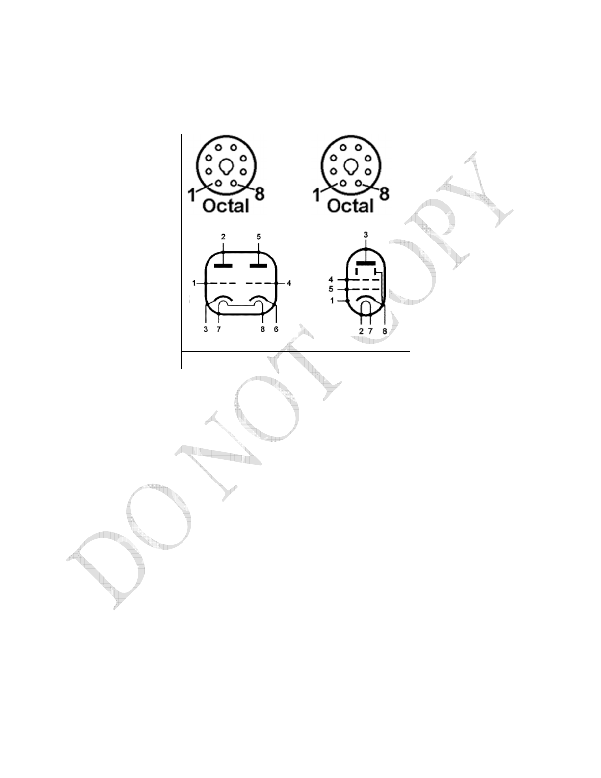
Tube Pin Numbering
The pins on an 8-pin tube socket are numbered 1 to 8 in a clockwise direction when viewed from the bottom.
Note that there is a key to ensure the tube is inserted correctly into the socket.
6SL7 6L6 /KT88
6SL7 6L6 /KT88
The pins on the potentiometers are numbered 1 to 3 from left to right when the shaft is facing towards you
and the pins are at the top.

TrinityAmps Trip Top Builders Guide Ver1.9.docx
- 26 -
Assembly Steps Summary
1. Install Hardware on the Chassis.
2. Wire up the heater wires to the sockets.
3. Install Transformers on the chassis.
4. Wire up the power supply - Mains, Transformers, power switch and pilot light.
5. Assemble the turret board and Install on chassis.
6. Connect turret board leads to tubes installing off-board parts as you proceed.
7. Connect turret board leads to controls installing off-board parts as you proceed.
8. Remove input jacks. Wire with 3.3M film resistors and shielded cable. Re-install.
9. Check Wiring.
10. Follow Start-Up procedure.
T P
: On a copy of the layout, highlight the connections as you complete them to make sure they are
done correctly.
1. nstall the Hardware
There are many nuts bolts etc. required. Here are some guidelines.
Part Where to use
4-40 X 5/16
(no nuts
reqd.)
Mount tube sockets, [optional lock washer under head on threaded
chassis];
4-40 nuts Mounting terminal strips, ground point, IEC socket
4-40 X 7/16
If supplied – to mount tube sockets with terminal strip, use nut to hold
terminal strip with nut/lock washer or lock nut Use with nuts/lock
washer to mount IEC connector, 5 lug terminal strip and 1-#4 pre-amp
chassis lug
Mount tube sockets on non-threaded chassis with lock nut
6-32 X 3/8 Mount 3 star ground # 6 chassis lugs with lock nut. Mount Capacitor
clamp; mount power ground lug in some amps
6-32 X 1 Mount turret board to chassis using stand-off. Use with lock nut.
8-32 X 3/8 Mount Mains ground ONLY. Use KEPS nut with lock washer and #8
chassis lug.
8-32 X 3/8 Mount Output and Power trans. With KEPS lock nuts.
8-32 lock nuts “KEPS” for power transformer; power ground bolt.
10-32 X 2 Mount chassis to cabinet. Use cage nuts in square holes pressed into
chassis.

TrinityAmps Trip Top Builders Guide Ver1.9.docx
- 27 -
#4-2
#6
#8
#8
#4-2
#4-2
#4-2
#4-2
#4-2
#6-2
#6
#10 CAGE NUT
#10 CAGE NUT
#4
#4
#6
Insert the 4 Cage Nuts by setting them in place in the square hole, one side fitting into the square hole and
then using a straight blade screwdriver, press in the cage on the opposite side so it snaps into position when
pushed into the square hole indicated above (#10 Cage Nut).

TrinityAmps Trip Top Builders Guide Ver1.9.docx
- 30 -
TR P TOP Rear
2 Wiring
Here is a guideline for wiring the kits with the supplied wire:
• Use 22 gauge colour solid for hook up from board to tubes using the following colour code chart.
22 Gauge Colour 6SL7 6L6 / KT66
Orange Plates 2, 5 3
Yellow Grids 1, 4 5
Blue Cathodes 3, 6 8
White Controls to board
Green Ground
• Use 20 gauge solid pre-twisted Red-Black pair supplied for tube heater wiring
• Use Black, White 18 Gauge, stranded, for power supply hook up - to transformers from IEC socket.
• Re-use cut offs from the transformers for the power supply side.
• Use RG174U for coaxial connections as indicated on the layout

TrinityAmps Trip Top Builders Guide Ver1.9.docx
- 31 -
Grounding Scheme
The TRIP TOP use a single star-point
grounding scheme where the power side of
the amp is connected to a single common
ground point, and the preamp part is
connected to the same point on the chassis.
For grounding these amps, we strongly
recommend that you follow the layout
provided. We don’t recommend that you
deviate.
There is also a separate AC supply safety
ground point near the IEC connector, which
doesn't form part of the actual amplifier
circuit. WARNING: THIS CONNECTION
IS VITAL FOR SAFETY REASONS.
Heater Wiring
This is tight wiring so set it up correctly and check and then finally install the power transformer and solder
everything in place on V5.
Note: After you install the power transformer, in the next step, you will connect each of the Green twisted
heater wires from the Power Transformer to the Lower hole in the socket tube pins 7 and 2 of V5. See next
step on installing the power transformer. You may choose to install the Power Transformer now, but it will
make moving the chassis difficult.
For connection to the tubes heater wires and hum control left and right terminals, connect two twisted 20
gauge wires to the Upper hole in the socket tube pins 7 and 2 of V5. Then connect these to pins 2 and 7
respectively of Power Tube V4. From there, the wires daisy chain across the preamp tubes, V3, V2, V1 Red
wire to pins 7 of each preamp tube and the Black wire to pin 8. This phasing or ‘polarity’ on the preamp
heaters needs to be maintained. The two power tube sockets V5, V4 also need to have their heaters wired in
the same phase (using the same colours) to minimize hum.
Connect a short piece of twisted 20 gauge wire from the Upper hole in tube pin 7 and 2 of V5 to the hum
control left and right terminals,

TrinityAmps Trip Top Builders Guide Ver1.9.docx
- 32 -
It is important to wire the tube filaments carefully. Use the pre-twisted 20 gauge solid core wire to minimize
any hum.
3 nstall Transformers
Install the power transformer. The Power transformer lies down along the chassis ‘long axis’. Align the AC
mains leads so they face towards the outside of the chassis. The High voltage (Red - Red/Yellow - Red),
Heater leads (Green – Green)and Rectifier Heater leads (Yellow –Yellow) face inwards. Feed the leads
through the 2 grommets installed in the chassis. Bolt the transformer in place with the supplied 4 each of 8-
32 bolts & KEPS nuts.
On the screw closest to the power switch, install a Terminal strip under the nut. You may need to cut the
mounting tab in order to allow it to “open up” to fit the #8 screw.
Tightly twist the AC mains lead pairs for your local voltage.
Install the Output transformer. The Output transformer lies down along the chassis ‘short axis’. Braid the
Primary leads together (Brown – Red – Blue) Braid the secondary winding leads (Yellow (4 ohm), Green (8),
Orange (16) Black (Common).
Align the Primary leads so they are pointing towards the front of the chassis. Feed the leads through the
grommets installed in the chassis with the Primary and Secondary leads going through separate grommets.
Bolt the transformer in place with the supplied 4 each of 8-32 bolts & KEPS nuts. The secondary leads
should be in-line with the impedance switch.

TrinityAmps Trip Top Builders Guide Ver1.9.docx
- 33 -
4 Power Supply Wiring
Now is the time to wire up the main
power feed. Use stranded cut-offs from
the transformers or some solid core wire.
Start with the IEC socket and
ensure it is grounded to the #6
chassis lug on the chassis beside the can
cap bracket. Tighten the ground bolt
tightly. Run a wire from the ‘Hot’ or
‘Line’ side of the IEC connector to the
lug on the END of the fuse holder and
from the SIDE of the fuse holder to the
power switch.
The other side of the IEC socket or
‘Neutral’ gets connected to the
‘Common’ side of the power
transformer.
Wiring of Mains Power cords: European vs North America
Ground Hot (L) Neutral (N)
Europe Green/White or Green/Yellow Brown Blue
North America Green [USA-plug round prong] Black [Small
flat prong]
White [Large
flat prong]
European 230V Green/White or Green/Yellow It makes no difference how the
other two wires are matched.
From the Power Transformer, Connect the High Voltage Centre Tap Red-Yellow to the power amp 3 lug,
Star Ground point located between the 50/50 uF can cap and V6.
From the Power Transformer, take the Green (6.3V Tube Heater pair) pair of wires and tightly twist them.
Route the twisted pair wire through the chassis, following the layout diagram, pressing it flat against the
chassis. Cut, strip and solder them to the first power tube, V5, Lower hole of pins 7 and 2.
From the Power Transformer, take the Yellow (5V Rectifier Heater pair) pair of wires and tightly twist them.
Cut, strip and solder them to the Rectifier tube, V6, pins 8 and 2.
From the Power Transformer, take the Red (High Voltage) pair of wires and tightly twist them.
Route the twisted pair wire around the outside perimeter of the chassis, following the layout diagram, pressing
it flat against the chassis. Cut, strip and solder them to the Rectifier tube, V6, pins 4 and 6.
Other manuals for TRIP TOP
1
Table of contents
Other Trinity Amps Amplifier manuals

Trinity Amps
Trinity Amps Trinity Tweed Amp User manual

Trinity Amps
Trinity Amps THOR User manual

Trinity Amps
Trinity Amps TriFly User manual

Trinity Amps
Trinity Amps Triton User manual

Trinity Amps
Trinity Amps Tramp User manual

Trinity Amps
Trinity Amps OSD User manual

Trinity Amps
Trinity Amps TRIWATT User manual

Trinity Amps
Trinity Amps Tube Effects Loop User manual


