HB Ross Manufacturing Co. ACVGD ROSS METER User manual


2
THE ACVGD®ROSS METER®
USER MANUAL
Published by the H.B. ROSS MANUFACTURING COMPANY, LLC.
in Richmond, Virginia. U.S.A.
© 2017 H.B. ROSS MANUFACTURING COMPANY. All Rights Reserved.
ACVGD® and Ross Meter® are registered trademarks of the
HB ROSS MANUFACTURING COMPANY, LLC.
- Since 1975 -

3
TABLE OF CONTENTS
1.0 DIRECTIONS FOR USING THE ACVGD®…………………………………………………………...4
1.1 Background….……………………………………………………………………………………..4
1.2 On the Job Site…………………………………………………………………………………....4
1.3 Taking Readings…………………………………………………………………………………..4
1.4 The Zero Reading Point…………………………………………………………………………..5
1.5 Other Reading Techniques……………………………………………………………………….6
1.5.1 The Triangulation Technique……………………………………………………………6
1.5.2 The Cable Path Technique……………………………………………………………...6
1.6 Typical Users Actual Practice…………………………………………………………………….7
2.0 GENERAL INFORMATION ABOUT THE ACVGD® ……….…………………………………………9
2.1 Warranty……………………………………………………………………………………………9
2.2 Battery Replacement……………………………………………………………………………...9
2.3 Probe Construction………………………………………………………………………………..9
2.4 Product Redesign Notice……………………………………………………………………..…10
2.5 Disclaimer…………………………………………………………………………………………10
FIGURE 1 and FIGURE 2………………………………………………………………………………….11
FIGURE 3…………………………………………………………………………………………………….12
WHAT’S INCLUDED WITH THE ACVGD®………………………………………………………….......13
MANUFACTURER CONTACT INFORMATION…………………………………………………………14
INSTANT JUMP TO MANUFACTURER WEBSITE (QR CODE)……………………………………...14

4
1.0 DIRECTIONS FOR USING THE ACVGD®
1.1 BACKGROUND –The alphabetic characters of the
trademark, ACVGD®, form an abbreviation, a symbol, for our
use to more simply name the instrument which was orginially
known as the 60 Hz A.C. Voltage Gradient Detector. The
ACVGD®ROSS METER®is an instrument designed to locate
the point along an underground cable path where a "fault to
the surrounding earth" is occurring. The ACVGD®makes use
of the existing 60 hertz A.C. voltage that is still energizing the
faulted cable. The ACVGD®does not require that any
secondary voltage service cables be disconnected in order to
use it. The operator merely walks out to where the cable is
buried and begins to probe along the path of the cable as
described below. Since the instrument does not put a signal onto the faulted cable the instrument is
“Passive in Nature” both in its design and in its use in locating the fault. Because of this passive nature
the instrument does not introduce any additional risk to the job site nor to the operator/user than was
present prior to arrival at the job location.
1.2 ON THE JOB SITE –The ACVGD®is easy to use and its
application to the job of locating the precise location of the
fault can be mastered in just a few times of use. The following
discussion explains the techniques used to locate secondary
voltage (less than 600 VAC) service cable faults with the
ACVGD®. Please refer to the attached drawings throughout
this discussion on the use of the ACVGD®.Figure 1 shows a
typical layout of facilities in a customer's yard. There is a chain
link fence, underground water pipes, and the underground secondary service. There is an earth ground at
the customer's meter base and there is another at the pad-mount transformer. These grounds may be
solidly (electrically) connected to the underground pipes and possibly even to the chain link fence.
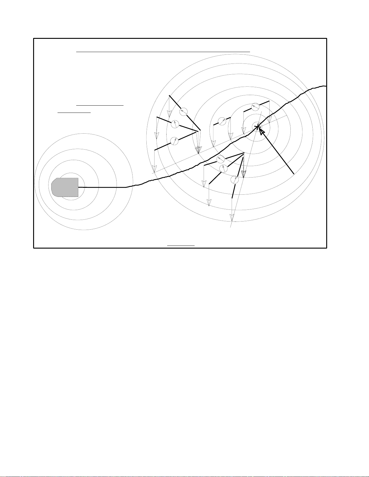
1.3 TAKING READINGS –Let's look at Figure 2 for the basic method of taking readings with the
instrument. Here the readings are represented as circular shapes, each being a specific voltage's pattern
that is generated at the surface of the ground. You also see there is an area that is labeled the
transformer zone on the left and the fault zone to the right. Of course, you cannot know immediately
where the fault zone is, but you do know where the source transformer is and where the customer's
meter base or street light is. With this in mind the following rule was developed (by user experience in
the field) as a time saving approach to finding the point of the fault.
THE 2/3's RULE
Observe the relative locations of the metered service point (that is
experiencing problems) and the source transformer. Walk to a
position that is approximately 2/3's of the way from the transformer
toward the metered service point. Position yourself along what
you would consider the probable path of the underground service.
This is where you should begin to take readings with the ACVGD®.
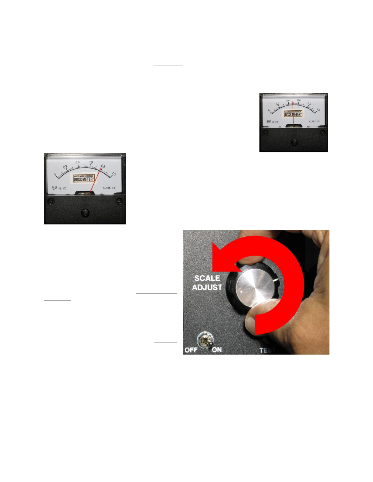
With the SCALE ADJUST knob turned fully Clock Wise (CW; ie, ⟳) place the probes at a comfortable
distance from your sides and push them into the ground enough to establish a firm contact with the soil. It
is not necessary to try to stick the probe tips deep into the soil in order for the instrument to detect the
presence of an A.C. voltage in the soil. However, it is important to try and maintain a similar amount of
depression into the soil, and a consistent distance between the probes, from one reading to the next.
This will help you to make the "comparisons" of the readings (from one sample reading to the next) more
meaningful. In other words, if the probes will easily penetrate two inches into the soil then try to take all
5
the readings by sticking them into the soil about two or three inches deep. If you go five or six inches
deep, after taking readings at two inches deep, the A.C. voltage, at the deeper point, will likely provide a
significantly higher reading, which could temporarily mislead you into thinking the fault point is closer than
it actually is. Also, when you hold the probes 'comfortably' at your sides if they are about 3 to 3.5 feet from
each other then you should try to maintain about that same distance between them as you probe for the
voltage reading.
Let's assume that the first location of your probes is represented by position
#1 as shown in Figure 2. Assuming that there is sufficient A.C. voltage signal
from the fault to cause the instrument's meter to give an up-scale indication,
you can make a mental note of how high the reading is at that position. Leave
one of the probes in place and move the other one about 45 degrees Counter
Clock Wise (CCW; ie, ⟲) around from its original position. This brings you
into position #2 and you can see a higher reading than you had in position #1.
Successive readings, moving the one probe CCW (⟲) will bring you to
the point of "highest" relative reading. This "highest" reading position
establishes the 'general direction' of the fault. This is the path indicated
by the dashed line that is drawn between the probe tip positions on the
ground. Next, you will have to determine which way you should move
along the dashed line shown in Figure 2. Move along the line in either
direction you choose. If the reading you get after moving is higher than
the previous then continue to move along the line in that direction. If the
reading is lower than the first then go the other direction along the line
and follow that procedure until you approach the point of the fault.
1.4 –THE ZERO READING POINT –As you
move closer to the fault, you will have to turn the
SCALE ADJUST knob counterclockwise (CCW;
⟲) in order to keep the indicating needle of the
panel meter from staying pegged solidly at the
right side of the scale. Again, what you will
observe is a pattern of increasing readings as
you move toward the fault. Then as you pass
one probe just beyond the point where the fault
actually is you will notice a decline in the relative
reading. Moving the probes in football chain
fashion in the same direction will again result in a
lower relative reading. If you go too far the
readings will rise sharply at first; but, as you
continue moving in that direction the readings will
become lower and lower. However, you can find
a point shown as position #5 in Figure 2 where
the reading is essentially ZERO. At this point you
will be standing directly above the fault. Why does a ZERO reading indicate the point of the fault?
Realizing that the voltage patterns in the soil are in the shape of concentric circles around the point of the
fault, note the diagram of dashed lines in Figure 2. Thus, when you have both probes on the same
"voltage pattern circle" there is no difference for the instrument to read, hence it will indicate ZERO. It is
this ZERO reading position that you are looking for.

6
1.5 –OTHER READING TECHNIQUES
Two other techniques you may choose to use in locating the point of the fault are:
1.5.1 -THE TRIANGULATION TECHNIQUE
Now let's look at Figure 3. You will notice that it is essentially the same as Figure 2 but another set of
readings is shown. Here you see that the 'general direction' indicated by position #C establishes a
second line of direction and this second line intersects the one that was established in Figure 2. It is
at this point of intersection that you would expect to find the fault. This is referred to as the
triangulation technique for locating the point of the fault. You probably see already how to achieve this
but let's run through it briefly;
(1) Take your first set of readings as shown in position #1 through #3 and note the 'general
direction' line the probes establish;
(2) Next, pick another position about 12 to 15 feet to the side (along the 90 degree line) of position
#3;
(3) Determine the 'general direction' as shown in position #C. Observe the indicated point of inter-
section of the two 'general direction' lines.
(4) Probe along this second line in football chain fashion in the direction of the intersection point.
The closer to the fault that these initial indications are found the
better the accuracy of determining the intersection point. If you
appear to be 15 to 20 feet from the intersection point you should
take several more readings along both of the direction lines
established above. When you work the readings of both
direction lines to within 4 to 6 feet of the intersection point you
can "literally" draw two lines in the soil for the direction lines you
have been following and the point where they cross will be very
close to the point of the fault. It is recommended, however, that
you confirm the actual point by finding the ZERO reading point
(described previously) along both direction lines. If the ZERO
reading points, as determined along both direction lines,
coincide then you can be confident that there is A.C. voltage present from some source at that point
in the soil.
Some users prefer to begin their probing with the ACVGD®after they assure themselves of the exact
path of the underground service cables, because (for them) this adds an element of certainty that they
are probing in the correct area(s). This technique we shall refer to as:
1.5.2 -THE CABLE-PATH TECHNIQUE
With this approach you would simply use any "path finding" equipment, that you may already have,
that can sense the presence of the electromagnetic field emitted by the energized service wires.
After marking or mentally noting the path of the conductors, you would then go to the location (along
this path) about 2/3's of the distance from the pad-mount transformer toward the metered service
point. There you would begin to take readings in football chain fashion (in your choice of direction)
along the actual path of the conductors. Depending upon where the fault is from this initial point, you
may find;
(1) that you have no readings even at the full clockwise (CW; ie, ⟳) setting of the SCALE
ADJUST knob, in which case you have to decide which direction to move along the cable path

7
to continue taking readings. If you go far from the starting location without getting any readings
you probably should go back to the 2/3's point, to start again, and probe in the other direction.
Remember that as you get close to the source
transformer (into the transformer zone) you will
begin to get readings due to the a.c. current flowing
back to the transformer's grounding rod. As was
pointed out in the opening discussion, the voltage
patterns will make a more concentrated pattern at
both the point of the fault and at the pad-mount
transformer's ground rod. You need to be mindful
of this since you will almost always find strong
readings within 6 to 8 feet of the pad-mount
transformer,or near the ground rod at the base of the overhead transformer pole, that serves
underground secondary service conductors. Of course there are times when the fault is within
the area of the transformer and the hunt for the exact spot of the fault is more difficult,but still
possible.
(2) that you have readings and so you move the probes in football chain fashion, in either direction
you choose, to get your next comparison reading. Then if the next reading is higher you can be
reasonably confident that you should continue moving along the cable's path in that direction.
However, if the readings seem to be getting lower then you should go in the opposite direction.
Once you have determined the direction that produces higher readings you simply continue, in
football chain fashion, along the cable's path until the readings drop off sharply and you can find the
ZERO point as described in the ZERO POINT paragraph above.
The technique that you may use is a personal choice, it depends on what you feel comfortable with. In
either approach it may be of some help if you take a sample reading about 8 feet from the source
transformer (within the "transformer zone") to determine how high the reading may actually be when you
begin to come close to the point of the fault (within the fault zone).
1.6 –TYPICAL USERS ACTUAL PRACTICE
The football chain technique of probe
movement described in the previous
paragraph(s) is what you can use once you
come near to the fault location. However, the
real-world user technique (as reported by
users) for getting into the general area of the
fault is a bit more “swashbuckling” than has
been described thus far. Football chain
movement is rather clumsy and it is more
comfortable to be able to walk straight ahead
as one is probing for the fault. Whenever the
"seasoned user" begins to probe at a new job
site; instead of initially moving the probes in
football chain fashion, the operator positions
himself/herself such that they have the probes stuck in the ground, one at each side of their body, and
they are facing in the direction they wish to walk to begin the probing process. Then the operator keeps
one probe in the ground (we will call it probe “A”) as he/she steps forward one step moving the other probe
(probe “B”) ahead of probe “A” and then sticks probe “B” into the ground. At this position the operator
looks to see whether there is any change in the panel meter reading, either higher or lower, from the
previous position where probes “A” and “B” were both stuck in the ground. If there is an increased reading
then the operator keeps probe “B” in the ground and then steps forward again but this time moving probe
“A” ahead of probe “B” by one step and sticks probe “A” in the ground to see if the reading increases

8
again. Repeating this process until the panel meter reading reaches a maximum value and then begins
to decline will bring the operator within range of the fault point. This technique allows the user to move
along the cable path by walking in a straight ahead manner while moving the probes alongside their body.
Once the operator observes the PEAK reading and then sees a declining value on the ACVGD®panel
meter he/she can then utilize the football chain technique to move the probes to locate the exact point of
the fault by determining the ZERO reading point as described above.

9
2.0 GENERAL INFORMATION ABOUT THE ACVGD®
2.1 –WARRANTY
The ACVGD®instrument, and the probes, are guaranteed to be free from material and manufacturing
defects for a period of one (1) year from the date of shipment to buyer. The probe tips are not
warranted against normal wear and tear.
The ACVGD®instrument is guaranteed self-protected for 60HZ A.C. voltages up to 300 Volts-
RMS. Application of voltages higher than 300 Volts-RMS may result in failure of the circuit's
electronics and in such event the warranty is void.
The instrument storage box (either orange or white in color) is guaranteed for ninety (90) days.
Batteries are not guaranteed.
Modification of the Instrument, or the Probes, by anyone other than the Manufacturer will VOID the
Warranty.
2.2 –BATTERY REPLACEMENT
It is recommended that you use alkaline
type, 9 volt batteries of a type similar to
the Duracell Plus Power DuraLock
MN1604 or the UltraLife U9VL-BP
Lithium batteries. NOTE: For very cold
weather conditions (which cause most
batteries to loose their charge more
rapidly, especially when stored
outdoors) lithium batteries, such as the
UltraLife U9VL-BP, will hold their charge
longer and maintain their output closer
to the 9 volt level better than any other
type of battery currently available;
however, they are more expensive than
the Alkaline batteries.
There are two batteries in the instrument and you must replace both at the same time, otherwise the
instrument will soon begin erratic operation. If this happens, the first items to check are the batteries.
Since the BATT-TEST push-button on the face of the instrument takes the reading from only one
battery,you will have to swap the two batteries in order to read the condition of the second battery.
Remember, when in doubt, remove both batteries and check them with a voltmeter. You should replace
them whenever they read less than 7.5 volts.
To replace the batteries you must first remove the four screws that secure the faceplate to the box. Then
you can lift the faceplate up until you see the batteries inside. Use your finger to lift each battery out of the
metal clip. Set the faceplate and the two batteries next to the top edge of the instrument. Now you simply
unsnap the old batteries from their connectors and then reverse the process to install the new batteries.
2.3 –PROBE CONSTRUCTION
The probe body is made of industrial quality Isophthalic Polyester Resin, reinforced with fiberglass, that
has excellent electrical, thermal, and mechanical properties for this application. It is similar to the “hot-
sticks” used by electric utility crews. The probe wiring is 18 AWG test probe wire rated at 5,000 volts d.c.
When the banana jack plugs are plugged flush into the terminals of the instrument no electrical contact

10
points exist anywhere along the length of these wires. This is a safety feature that is designed into the
probes.
The probe tips are made of stainless steel (1/4 inch solid rod) for added strength and durability. One end
of the rod is threaded using a 1/4-20 NC die. The wire is secured to the end of the probe tip, within the
probe's handle, by two 1/4-20 NC finished (zinc coated) hex nuts.
2.4 –PRODUCT REDESIGN NOTICE
Your ACVGD®unit may come equipped with probes that were recently redesigned. Our previous design
included stainless steel hose clamps that held the stainless steel probe tips inside the probe. The new
design replaces the clamps with one or two piece oxide steel shaft collar clamps. These clamps are far
superior in many ways to the worm gear type of clamps that we used in the past. We’d like to hear your
feedback on this new design –both positive and negative. Most importantly, if you find any problems with
this new design, we’d like to know. Send us a quick note via email to troy@hbrossmfg.co.
Former Design
New Design
2.5 –DISCLAIMER
Working with electricity can be dangerous. Responsibility lies with
you, the user of the ACVGD®, to act safely when using this device.
Inspect the instrument before use. Be sure that the probe wires are
not damaged, exposing any conductor. The instrument must be
used in accordance with the manufacturer’s user manual and only
for the purpose which it was designed. The manufacturer and
distributor(s) of this product shall neither assume nor accept any
liability or responsibility for consequential damages or injury
resulting from the use or misuse of this product or any of its
component parts. In using this product, the user of the ACVGD®
assumes the responsibilities of ownership, use and operation and
the user agrees to hold harmless the manufacturer and its
distributors, partners and employees for any incident or action
involving the use of this product.

11
TYPICAL LAYOUT OF FACILITIES
Figure 1
GROUND
HOUSEHOLD
METER BASE
CHAIN LINK FENCE
U.G. WATER DISTRIBUTION PIPES
PADMOUNT
TRANSFORMER
GROUND
ROD
x x x x x x x x x
#1
#2
#3
#4
#5
TYPICAL PATTERN OF VOLTAGE CIRCLES NEAR THE SURFACE
FAULT ZONETRANSFORMER ZONE
EACH DASHED CIRCULAR SHAPE
REPRESENTS A SPECIFIC VOLTAGE
AND ITS PATTERN WITHIN THE SOIL
POINT OF
THE FAULT
Figure 2
UNDERGROUND SERVICE CABLE
12
#1
#2
#3
#4
#5
TRIANGULATION METHOD OF LOCATING THE FAULT POINT
FAULT ZONETRANSFORMER ZONE
EACH DASHED CIRCULAR SHAPE
REPRESENTS A SPECIFIC VOLTAGE
AND ITS PATTERN WITHIN THE SOIL
POINT OF
THE FAULT
Figure 3
#A
#B
#C

13
WHAT IS INCLUDED WITH THE ACVGD®ROSS METER®?
1. Utility Dry Box –(Outside Width: 7.75", Length: 15", Height: 6.5", Volume: 5.6 Liters) Orange in
color. Extra-thick co-polymer construction wall will not warp from sun, cold, or rough handling.
Hand-laid lid gasket seals the inside from moisture to protect the ACVGD®from damage. Strong
reinforced steel pin hinge system. Heavy-duty steel bar latch system with locking feature keeps
the ACVGD®safe and secure. A padlock (not included) may also be used, if desired.
2. The ACVGD® device includes two 9 volt batteries already installed in the unit. Its case is made of
thermoplastic ABS which is mar and scratch resistant, chemical resistant and heat resistant to
475 degrees. The handy neckstrap is made of light weight nylon webbing which is military spec
and has a breaking strength of 1200 pounds.
3. Two probes which are constructed of Isophthalic Polyester Resin reinforced with fiberglass. Each
probe includes the 18 AWG wiring which is rated at 5,000 volts D.C.Banana jack plugs are also
included which are used to connect the probes to the ACVGD® . The probe tips are made of
stainless steel T304 and are ¼” diameter (standard specification ASTM A276, QQS-763,
T304/304L).
4. One User Manual (physical form) and digital (available online via computer or smartphone).

Table of contents
Popular Measuring Instrument manuals by other brands


Endress+Hauser
Endress+Hauser Memosens CFS51 operating instructions

DeFelsko
DeFelsko PosiTector SHD instruction manual

Endress+Hauser
Endress+Hauser Levelflex M FMP43 operating instructions

amc VIBRO
amc VIBRO AV CONDITIONER 1000 user manual

EMCIS
EMCIS EA-300 Operation manual

PASCO
PASCO PS-3234 Product guide