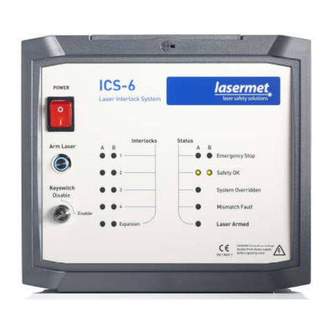
Lasermet ICS-LJIM User manual

LJIM Instruction Manual
02116-53-001 Issue 3 19 January 2021
LASERMET
LASER JAILMASTER
INSTRUCTION MANUAL
FAIL SAFE LASER INTERLOCK CONTROLLER AND
ACTIVE BEAMGUARD INTERFACE

LJIM Instruction Manual
02116-53-001 Page 2 of 30 Issue 3 19 January 2021
LASERMET ICS-LJIM
Instruction Manual
Contents
1 Declaration of Conformity .................................................................................................. 4
2 Safety Warnings .................................................................................................................. 5
3 Concept ............................................................................................................................... 6
4 Summary of Evaluation of Compliance to EN ISO 13849-1:2015 ....................................... 7
5 Installation .......................................................................................................................... 8
5.1 Positioning ................................................................................................................... 8
5.2 Front Panel .................................................................................................................. 8
6 Wiring ................................................................................................................................. 9
6.1 LJIM Inputs ................................................................................................................ 10
6.2 Interlock Operator Output Contacts ......................................................................... 10
6.3 Beam Shutters ........................................................................................................... 10
6.4 Shutter with own Power Supply................................................................................ 11
6.5 Interlock Connectors ................................................................................................. 12
6.6 Electromagnetic Door Locks ...................................................................................... 13
7 Expansion Units ................................................................................................................ 14
7.1 Front Panel ................................................................................................................ 14
7.2 Connections to Expansion Units ................................................................................ 15
7.3 Use of Expansion Units .............................................................................................. 15
8 Mismatch Detector ........................................................................................................... 16
8.1 Configurable Options for Safety Circuit Mismatch Events ........................................ 16
8.2 Clearing a Mismatch Fault Indication ........................................................................ 17
8.3 Mismatch Detector Remote Reset ............................................................................ 17
9 LED Indicators ................................................................................................................... 18
10 Operation ...................................................................................................................... 20
10.1 Starting Up ............................................................................................................. 20
10.2 Resuming Operation after ABG Fault .................................................................... 20

LJIM Instruction Manual
02116-53-001 Page 3 of 30 Issue 3 19 January 2021
11 Serial Interface .............................................................................................................. 21
11.1 Connections ........................................................................................................... 21
11.2 Modbus Operation ................................................................................................ 22
11.3 Register Access ...................................................................................................... 23
11.4 Example using Python ........................................................................................... 25
12 Connecting Expansion Units to ICS-7-OEM ................................................................... 27
13 Fuses ............................................................................................................................. 27
14 Specifications ................................................................................................................ 28
14.1 Main Unit ............................................................................................................... 28
14.2 Expansion Unit ....................................................................................................... 28
15 Warranty ....................................................................................................................... 29
16 Contact Details .............................................................................................................. 30

LJIM Instruction Manual
02116-53-001 Page 4 of 30 Issue 3 19 January 2021
1 Declaration of Conformity
LASERMET LIMITED
LASER JAILER INTERFACE MODULE
Part no. ICS-LJIM and ICS-LJIM-SO
DECLARATION OF CONFORMITY
This is to certify that the Laser Jail Master and Son of Laser Jail Master Expansion Board
designated by Lasermet Part Number ICS-LJIM and ICS-LJIM-SO respectively has been
tested in accordance with the following standards and found to comply.
Lasermet certifies that this product complies with the basic requirements for health
and safety as provided by the following Standards:
Standards: EN ISO 13849-1:2015
Safety of Machinery – Safety-related parts of Control Systems
Part 1: General Principles for Design
Supplier:
Lasermet Limited
Lasermet House
137 Hankinson Road
Bournemouth
BH9 1HR
Dorset
United Kingdom
Country of Origin: England
Date: 10 June 2019

LJIM Instruction Manual
02116-53-001 Page 5 of 30 Issue 3 19 January 2021
2 Safety Warnings
This device is intended to be used as part of a safety system which may be used to protect personnel
and equipment from possible injury, damage, or loss.
As such it must be installed and wired according to these instructions and tested by suitably qualified
persons. No attempt may be made to tamper with the parts, open them, or use them outside of the
parameters contained herein.
The units are only designed to be fixed to surfaces using their inbuilt fixing holes. They must not
come into contact with each other or any other moving part when in use. The parts should never be
subject to impact or mechanical strain.
Safety switches should never be defeated or bypassed. It is imperative that all steps are taken to
ensure that any spare actuators are made unavailable, such that they cannot be used to defeat the
switch or reduce the protection offered by the system in any way.
Glossary
EN European Normalised (Standard)
ICS Interlock Control System
ISO International Standards Organisation
LED Light-Emitting Diode
NC Normally Closed
NO Normally Open
OEM Other Equipment Manufacturer
PL Performance Level
PLC Programmable Logic Controller
SIL Safety Integrity Level
V Volts
VDC Volts (Direct Current)

LJIM Instruction Manual
02116-53-001 Page 6 of 30 Issue 3 19 January 2021
3 Concept
The LJIM provides control of an interlock system intended to protect persons and equipment from
accidental exposure to laser hazards caused by high power lasers. Its primary function is to actively
monitor the walls and windows of the laser enclosure and to shut down the laser if these are
compromised. This is achieved by using Lasermet’s proprietary Active Beamguard (ABG) technology.
The LJIM system includes two modules, the main unit and the expansion unit. The main unit includes
a laser interlock controller with two sets of interlock operator outputs and four separate ABG
monitor circuits. The expansion unit can be connected to the master unit to add four more ABG
monitor circuits to the system. Up to 31 expansion units can be connected to add more monitoring
for complex systems.
Two external volt-free contacts are required to arm the system. These might be from a PLC, for
example. When these contacts are both closed and all the necessary interlock input conditions are
met (all ABG circuits valid), the controller will arm and enable the laser. If the Arm contacts are then
opened the system will disarm.
If any ABG circuit is invalid (output contacts not closed) when the external Arm contacts are closed
the controller will not arm. If the ABG output contacts then close, the controller will still not arm.
This is to prevent an unexpected start-up of the laser. If the system fails to arm because of an ABG
fault condition, the Arm request should be removed and the fault located before the laser can be
reset.
The LJIM has a fully dual channel cross-checked architecture and when correctly wired can realise a
system compliant with EN ISO 13849-1 up to performance level ‘e’.
Two safety interlock outputs each rated at 4A resistive, 50VDC, are provided to enable the laser,
operate door locks, or provide signals to a PLC. The interlock outputs are volt-free contacts. Each
output comprises two contacts, one for each channel, operated by different relays. In the event of
one contact failing to open, the other contact will open and the system is then disabled, preventing
further use and maintaining safety.
The LJIM has a mismatch detector which disables the system in the event of a mismatch between
the two safety circuits. This provides protection against single fault conditions that leave one
channel stuck in the ‘OK’ state.
In addition to the safety-related circuitry, the LJIM has an RS485 serial connection intended for use
in status and diagnostic monitoring. It functions as a Modbus RTU slave and can communicate with a
Modbus master unit.
Lasermet provides a full range of equipment including interlock switches, illuminated warning signs,
laser shutters, entry keypads with built-in fail-safe override timer, door locks, external power
supplies etc. Some of these can be used to support the LJIM system. Full support, design and
installation is available from Lasermet; please contact us for any queries. Contact details are given at
the end of this manual

LJIM Instruction Manual
02116-53-001 Page 7 of 30 Issue 3 19 January 2021
4 Summary of Evaluation of Compliance to EN ISO 13849-1:2015
To achieve a complete system performance level ‘e’ the system must be wired as described in this
manual using suitably rated door sensors and measures taken to minimise the effects of common
cause failures in the sensors and wiring which may be connected to the unit.
In service operation 365 days/year
- 2 x eight-hour shifts
Functional demand on the controller once per half hour
Main Unit Achieved Characteristics:
Architecture Category 4
Performance Level (PL) PL = e
PFH [1/h] 2.03 x 10⁻⁸
MTTFd 126 years
Mission Time 20 years
Diagnostic Coverage (DC) 99% (HIGH)
Expansion Unit Achieved Characteristics:
Architecture Category 4
Performance Level (PL) PL = e
PFH [1/h] 9.81 x 10⁻⁹
MTTFd 247 years
Mission Time 20 years
Diagnostic Coverage (DC) 99% (HIGH)

LJIM Instruction Manual
02116-53-001 Page 8 of 30 Issue 3 19 January 2021
5 Installation
The LJIM is designed to be attached to a 35mm ‘top-hat’ style DIN rail inside a control cabinet. It
should always be enclosed in a cabinet that requires use of a tool or key to open to prevent
tampering and risk of touching live connections.
While the unit itself operates on 24V it is possible that higher voltages fed from other equipment
may be present on its output contacts.
5.1 Positioning
The LJIM should be mounted in a convenient position for wiring. It should be inaccessible by
operators. It has indicator lights on its top surface which would normally only need to be observed
by installation and maintenance personnel.
Provision should be made to prevent the unit from sliding along the DIN rail after fitting, for example
by the use of end clamps or other equipment.
During installation, wired connections will need to be made from the LJIM to the monitored
windows and wall panels required by the system. Allowance should be made for wire retention such
as plastic slotted trunking running alongside both long sides of the unit.
5.2 Front Panel
The terminals are identified on the label on the top of the unit, as shown below. Holes in the label
are shown in yellow and windows for LEDs are shown in red.
LJIM master top label showing terminal identification

LJIM Instruction Manual
02116-53-001 Page 9 of 30 Issue 3 19 January 2021
The ABG indicator LEDs show the status of each ABG monitor. The Break LEDs light when an ABG
track has been broken. The Leak LEDs light when conduction has been detected from the track.
The dual-channel ABG inputs are wired A-B-A-B to maximise the detection of wiring errors. The
other dual-channel inputs and outputs are wired A-B-B-A in line with Lasermet’s normal practice.
Input signals are indicated by a green background, while the interlock outputs have a pink
background. Fault status indications have an orange background.
6 Wiring
A typical wiring scheme for the LJIM is shown in the diagram. Be sure you know which configuration
you require before you attempt to wire the unit. If you require further assistance, please call
Lasermet technical help. Contact details are at the end of this manual.
Example overall wiring scheme

LJIM Instruction Manual
02116-53-001 Page 10 of 30 Issue 3 19 January 2021
6.1 LJIM Inputs
Active Beamguard (ABG) inputs
Up to four dual-channel ABG circuits may be directly wired to the LJIM. These circuits consist of
resistive tracking, either on wall panels or manufactured as part of enclosure windows.
A 4-way pluggable terminal block is provided for each circuit. One of the ABG tracks is wired to the
‘A’ terminals. The other track is wired to the ‘B’ terminals.
Circuits that are not used must be completed by wire links or resistors (e.g. a 4k7 resistor).
6.2 Interlock Operator Output Contacts
The LJIM has two dual-channel volt-free interlock operator output contacts (outputs 1-2) which may
be used for various purposes including:
Operating warning signs;
Controlling beam shutters;
Operating the laser’s interlock input;
Controlling door locks;
Signalling the state of the controller to a PLC.
6.3 Beam Shutters
The LJIM may operate one or more beam shutters and one or more laser interlocks. For permanent
fixed installations these may be directly wired to the LJIM. Where there is any possibility of the
equipment being changed or moved it is often most convenient to be able to unplug the equipment.
Lasermet provide a range of small distribution boxes which allow for convenient positioning of wall
or surface-mounted plugs for laser interlocks and sockets for shutters. The boxes are available with
different combinations of plugs and sockets.
Modern industrial lasers are usually equipped with dual channel interlock inputs which may be
directly connected to one of the dual channel outputs of the LJIM as described in this manual.
Many smaller lasers only have a single channel interlock input which can present problems if the
safety system has to comply with ISO 13849 performance level ‘e’ since two methods of control are
usually required. Some lasers have internal beam shutters which may be controlled by the LJIM. If
the laser has two means of disabling, e.g. interlock and internal shutter, it is recommended that both
are used. Otherwise it may be necessary to consider having an external shutter in addition to the
laser’s own interlock if a high safety integrity is required.
Lasermet’s beam shutters are supplied with suitable leads to plug into the distribution boxes. Open-
ended leads are provided for laser interlocks allowing the customer to fit the correct plug for his
laser.

LJIM Instruction Manual
02116-53-001 Page 11 of 30 Issue 3 19 January 2021
LS-10 Shutter
Use the above circuit. Note that older versions of LS-10 will only work off a 12VDC supply.
LS-20 and LS-200 Shutter
The LS-20 and LS-200 Shutters can use the above circuit. However, if monitoring of the shutter state
is required it is recommended that the ICS-7-OEM controller, which has monitoring inputs, is used.
Please contact Lasermet for further details.
6.4 Shutter with own Power Supply
For shutters that have their own power supply or are to be run from an existing supply, you can use
one of the controller outputs to operate them. If the shutter requires a single contact to operate it,
connect the A and B contacts of the controller output in series as shown in the wiring diagrams
above for LS shutters, so that the shutter closes if either one or both output contacts open.
The connections should be arranged so that the shutter closes when the Interlock Operator contact
opens. Any LJIM output used for shutters must not also be used for laser interlock control.
The contact is limited to 4A resistive load. If your shutter is solenoid-based it may need a protection
diode fitted to prevent possible damage to the LJIM.

LJIM Instruction Manual
02116-53-001 Page 12 of 30 Issue 3 19 January 2021
6.5 Interlock Connectors
Any of the LJIM output contacts may be used to operate a laser’s interlock control, provided they
haven’t been used for any other purpose. The contacts are closed when the LJIM is armed. If there is
more than one laser each must use its own output connector on the LJIM. Interlock sockets of
several lasers must not be connected together.
Where the controller is part of a fixed laser system it is usual to directly connect the two devices. For
lasers with a single interlock channel use the following connections:
For lasers with dual channel interlocks use the following connections:
Where the laser may be removed from the system or exchanged, a Lasermet Distribution Box may
be used to provide a connection point convenient to the laser. In this case for lasers with a single
channel interlock, the A and B LJIM output channels are connected in series to pins 1 and 2 of the
plug of the distribution box. See the diagram below.
Leads are available in various lengths to plug into the distribution box. The other end of the lead is
unconnected to allow fitting of a plug suitable for the laser.
Most industrial lasers are now designed to be compliant with EN 13849-1 and feature two interlock
input channels. This will require a distribution plug and socket with more connections.

LJIM Instruction Manual
02116-53-001 Page 13 of 30 Issue 3 19 January 2021
6.6 Electromagnetic Door Locks
Use only fail-safe door locks provided by Lasermet (electric door strikes or maglocks). These will
prevent access to the room while the laser is on while always allowing people to enter or leave the
room in the event of a power loss. In order to ensure that people can always enter or leave the
room in the event of an emergency it will be necessary to put an emergency stop or break glass
switch near each door. If in doubt, call Lasermet technical help.
The door should be fitted with interlock switches so that the laser is disabled if a door is opened
using the break glass switch.
Note that several maglocks can be wired in parallel from the same LJIM output provided the 4A
maximum rating of the contact is not exceeded.
Some locks can be configured for 12V or 24V supply. They should be set for 24V operation and run
off the 24V supply to reduce the current consumption to 0.25A per lock. To set the Maglock for 24V
operation, open the terminal access cover on the lock. Remove the two black links from the circuit
board and refit one of them across the middle two pins. Park the spare link with one side on one of
the empty end pins so it is not lost. If in doubt, refer to the instructions supplied with the maglock.
In all cases a diode rated at 1A 50V or more must be wired directly across the terminals of each door
lock. Lasermet’s Maglocks usually have the diode fitted as standard, in which case it is essential that
the supply is connected the right way round.

LJIM Instruction Manual
02116-53-001 Page 14 of 30 Issue 3 19 January 2021
7 Expansion Units
The LJIM can be connected to one or more Lasermet Laser Jailer Expansion Units which extend the
main unit by providing more ABG monitor sections.
The signalling from the expansion units is provided by dual relay contacts. Essentially there is no limit
on the number of contacts that can be connected, since the resistance of each individual contact is
so low.
In order to test the operation of the monitors, a test connection is also provided. This is normally at
+24V. When lowered to 0V, the expansion unit performs a self-test on each of its channels. If the
self-test is successful, the output contacts are re-enabled. If the self-test fails, one of the contacts
will remain open. The self-test is requested by the LJIM every time the unit is armed.
7.1 Front Panel
All of the terminals are identified on the label on the top of the unit, as shown below. Windows for
LEDs are shown in red.
LJIE Laser Jailer Expansion Module
ABG input connections to the expansion unit are the same as for the main unit. The output
connections are dual-channel volt-free contacts indicating that the ABG section is in the safe state.

LJIM Instruction Manual
02116-53-001 Page 15 of 30 Issue 3 19 January 2021
7.2 Connections to Expansion Units
The diagram shows the connections for two expansion units. The dual-channel outputs are daisy-
chained to the expansion input on the LJIM. Further expansion units can be added, keeping their
output contacts in series. The test connections are made in the same manner. The two test terminals
on the expansion units are actually connected together, but two terminals are provided to facilitate
wiring as a continuous loop.
If no expansion units are used, the expansion inputs should be linked A-A and B-B, and the test
terminals should also be linked.
7.3 Use of Expansion Units
Self-test Failures
The self-test function is included so that the LJIM and the expansion units can check the integrity of
their own active beamguard monitoring circuitry. No faults would normally be expected. However, a
fault on one channel of the active beamguard window or panel circuits may also lead to a self-test
fail, which will lead to a mismatch indication even after the ABG fault has been cleared. In this case,
cycling the test connection at the LJIM will clear the fault. When setting up the system for the first
time, it may be desirable to put a switch in the test connection. Switching this off, then on, will re-
run the self-test, clearing any fault indications for faults that have been fixed.
Monitoring Status of the Expansion Units
The expansion units have the same ABG status LEDs as the LJIM main unit, and also have LEDs to
indicate the status of their output relay. In addition (see later section), the LJIM and expansion units
can be connected to a Modbus master for centralised monitoring.
Extra Switches
Because the expansion connector requires volt-free contacts, extra switches can be included if
required. This might be used, for instance to provide a key lock facility. Any switches used should be
dual channel.

LJIM Instruction Manual
02116-53-001 Page 16 of 30 Issue 3 19 January 2021
8 Mismatch Detector
The LJIM trips out and disables the laser when either of its two safety circuits opens. It is normal for
both safety circuits to open more or less simultaneously.
If the second safety circuit does not open within a short time of the first (typically around 1.5
seconds), a mismatch is triggered and the ‘Fault’ light illuminates on the front panel. It is then not
possible to arm the system.
Because the LJIM is intended for active beamguard systems, which are always dual channel, no
provision has been made for disabling mismatch detection.
8.1 Configurable Options for Safety Circuit Mismatch Events
Mismatch Event Behaviour
In the event of a mismatch being detected either of the following two actions are available
depending on the option switch settings:
a) Lock out, preventing further use, unless the system is reset by switching it off and on again;
b) Lock out, preventing further use, unless the system is attended to by a qualified technician.
Option a) is suitable for mission-critical applications where the inability to use the laser would be
costly or inconvenient. Having detected and indicated that there is a fault it allows the system to be
reset to operate on the one good safety circuit provided the faulty circuit has been closed. The need
to manually reset the system before it can be used provides a clear indication to operators that
there is a problem that needs to be addressed at the earliest opportunity and that other risk
limitation steps may be required in the interim. An example might be to secure the affected door out
of use until it can be repaired.
Option b) is the lowest risk option, as once a safety circuit fault has been detected the system cannot
be used. The LJIM can only be reset by opening the cabinet in which it is mounted and operating the
Fault Reset button. Procedures should indicate that this is only carried out by suitably trained
technicians once the fault has been repaired.
By default, the mismatch detector is factory set to be enabled in option ‘a’ above.
Mismatch Detection Settings
The Safety Circuit Mismatch Detection behaviour is set by the option switch on the left-hand side of
the fuse. When closed, this switch enables automatic mismatch to reset on cycling the power. The
‘ON’ position is indicated on the switch.

LJIM Instruction Manual
02116-53-001 Page 17 of 30 Issue 3 19 January 2021
8.2 Clearing a Mismatch Fault Indication
In all cases the fact that a mismatch fault has been indicated warns users that the safety of the
system may be compromised. Site-specific instructions should indicate the actions to be taken by
users in such an event.
If the auto reset option has been selected, the system may be temporarily cleared by turning the
power supply off, waiting for ten seconds, then turning it back on again. In this case the system
should be attended to by a suitably qualified technician to identify and repair the fault at the earliest
opportunity as a fault has been identified and the system may cease to provide protection without
further warning.
If the LJIM has been configured to permanently lock out, it can only be reset by pressing the Fault
Reset button. This should only be undertaken by suitably qualified technicians once the fault has
been identified and repaired as otherwise the unit will just lock out again.
8.3 Mismatch Detector Remote Reset
Terminals are provided that allow for remote resetting of the mismatch detector if desired. The
‘reset’ switch should have a contact which closes to reset the detector. This could be provided by a
switch or a volt-free output from a PLC.
Contact Lasermet or your local distributor for assistance if you wish to use this feature.

LJIM Instruction Manual
02116-53-001 Page 18 of 30 Issue 3 19 January 2021
9 LED Indicators
ABG Status LEDs
Four LEDs are provided for each of the ABG monitors on the LJIM and expansion units. These
indicate ‘break’ and ‘leak’ conditions for each channel respectively.
If a track on the ABG window or panel is broken, the corresponding ‘break’ LED will illuminate. This is
the usual fault condition after a laser strike. It can also occur due to a disconnection in the circuit.
If conductance is detected between the A and B tracks on the ABG window or panel, the ‘leak’ LEDs
on both channels will illuminate. The tracks are normally isolated from each other and held at
different voltage levels, so this indicates a fault. This may be cause by a laser strike if the area
between the tracks has become carbonised. It may also be caused by a wiring short.
If the ‘leak’ LED on the A channel illuminates while the corresponding B channel LED remains off, this
probably indicates leakage from the tracks to ground. If the B channel ‘leak’ LED is illuminated, while
the A channel LED remains off, this may indicate leakage into the circuits from a local power supply.
If just one channel has a fault, the mismatch detector will disable the LJIM until it is reset.
‘Active Beamguard OK’ A and B
These LED’s will light in green when both ABG circuits on the LJIM are complete.
The system will not arm if either or both LED’s are unlit. If the self-test has failed, one of the LEDs
will be off even if there is no ABG status fault.
‘Arm’ A and B
The Arm indicators will illuminate blue when external contacts have closed in an attempt to arm the
controller. The controller will not arm if only one channel is closed, indicated by only one light being
illuminated.
‘Mismatch Fault’ LED
The LJIM continually monitors both safety circuits. If a mismatch occurs that lasts for more than
about 1.5 seconds, the Mismatch Detector is triggered, which disables the system and illuminates a
red ‘Fault’ light on the front panel.
The Mismatch Detector will detect a mismatch in the ABG circuits, the monitor inputs and its
internal arming circuitry.
Site-specific procedures may be applicable in such an event, which cover actions to be taken to
determine the cause of the fault, to have it rectified and to restore the system to operation. There
may also be procedures to allow operation in degraded mode until normal operation can be
restored.

LJIM Instruction Manual
02116-53-001 Page 19 of 30 Issue 3 19 January 2021
'Armed' LED’s
When the 'Active Beamguard OK' LEDs are lit and the external Arm contacts have been closed, the
'Armed' LEDs will light orange to warn that the LJIM has enabled the laser. If the ‘Active Beamguard
OK’ LEDs are illuminated but the ‘System Armed’ LEDs do not illuminate when the external Arm
contacts are closed, this could indicate that the internal checking circuitry of the LJIM has detected a
fault condition.
‘MCU Fault’ LED
The ABG status LEDs, Arm status LEDs and serial interface are controlled by a microcontroller. If this
has failed or has not been programmed, the ‘MCU Fault’ LED will illuminate. In this case, the ABG
status LEDs will not be valid.
Power Supply LEDs
Green ‘24V’ and ‘Expn +24V’ LEDs indicate that the main 24V power supply and the 24V switched
power supply to the ABG units are on. If the ‘24V’ LED is not illuminated, check the power supply
connection and the main power supply fuse (1A T). The ‘Expn +24V’ LED will briefly turn off during
the self-test phase. If it stays off, there is a fault in the LJIM circuitry.
‘Expansion Fault’ LEDs
The LJIM main unit has two red LEDs which light when the connections to the expansion input are
not closed. They will light briefly during the self-test, but if illuminated at any other time, the cause
should be investigated.

LJIM Instruction Manual
02116-53-001 Page 20 of 30 Issue 3 19 January 2021
10 Operation
Once correctly wired, the LJIM is extremely easy to use. The following instructions cover the most
common arrangements. For more complex customer-specific systems, additional procedures may
apply.
10.1 Starting Up
1. Apply 24V power to the controller.
2. The unit will normally be operated as part of a PLC system that will have various other inputs
that need to be satisfied. If the ABG inputs are all OK, and the expansion and test
connections are all closed, the LJIM will be ready to arm on a signal from the PLC.
3. The PLC or manual operator will than close the contacts connected to the ‘Arm’ terminals.
The unit will briefly run the self-test, during which the ABG status LEDs will flicker. If all is
well the amber ‘Armed’ lights will be illuminated on the front panel of the unit.
N.B. Be aware that this action restores power to the shutters or the laser, and may result in
accessible laser beams, depending on your system set up. This action should only be taken when
everyone is ready and the necessary safety precautions have been taken e.g. protective eyewear etc.
If an attempt to arm the system is made while an input is invalid, the controller will not arm even if
the input is restored. The external ‘Arm’ contacts must be opened, and a new arm attempt made.
10.2 Resuming Operation after ABG Fault
When a fault is detected by the ABG system, the LJIM will cut the power to the laser or the shutters
and the ‘Armed’ lights will be extinguished. To resume laser operation:
1. Open the Arm contacts.
2. Investigate the fault condition. Note the ABG LED status display on the front panel. This may
involve replacing an ABG panel or window if the fault was due to a laser strike, as these parts
are sacrificial. If the fault was a loose connection this can be identified and repaired.
3. Reset the mismatch detector (where necessary).
4. When ready to restart, close the external Arm contacts.
N.B. Be aware that this action restores power to the shutters or the laser, and may result in
accessible laser beams, depending on your system set up. This action should only be taken when
everyone is ready and the necessary safety precautions have been taken e.g. protective eyewear etc.
Table of contents
Other Lasermet Measuring Instrument manuals