TRIPLE ONDA TOP.S 12A User manual

TRIPLE ONDA S.A
C/ Bobinadora 95
08302 Mataró (Barcelona-SPAIN)
www.tripleonda.com
User guide TOP.S 12A
TRIPLE ONDA,
30 years designing, manufacturing and dealing
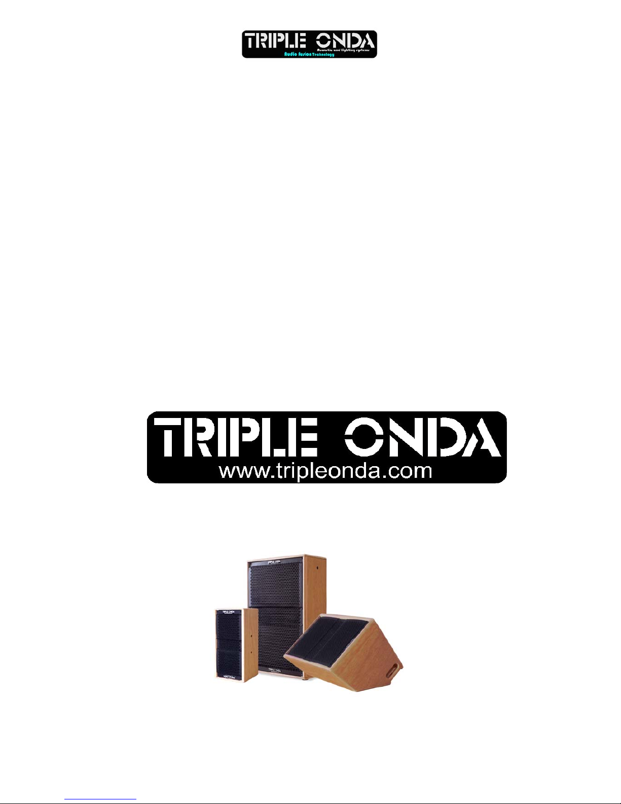
TRIPLE ONDA LAUNCHES A NEW PRODUCT
RANGE: TOP.S SERIES
Triple Onda launches a new product range,
called TOP.S Series, designed to cover medium
and little events.
New TOP.S Series cabinets are build-in
amplified and processed for professional
performance. As usual, all Triple Onda’s
products follows the same philosophy: high
quality design, robust and unusual products for
all the professionals who live on the live sound
every day.
.
1. INTRODUCTION
1.1. General
TRIPLE ONDA S.L. would like to thank you for
your confidence in our TOP.S Series cabinets.
A gathered experience of more than 30 years
designing acoustic cabinets and amplifiers,
applying most advanced analysis devices, has
allowed to TOP.S Series become the optimal
and ideal solution for fixed installations and
especially for live events. TOP.S Series’
lightness, quality, power, and reliability will
not fail to surprise!
We suggest you to carefully read the following
instructions in order to obtain the best results in
performance.
1.2. Safety Instructions
1. All the safety and operation instructions
should be read before this product is operated.
2. The exclamation point within an equilateral
triangle is intended to alert the user of the
presence of internal components whose
substitution may affect safety.
TOP.S 12A 2009
2
3. The lightning flash with arrowhead symbol
within an equilateral triangle is intended to alert
the user of the presence of uninsulated
dangerous voltage that may constitute a risk of
electric shock to persons.
4. This product should not be exposed to rain or
moisture. Do not use it, for example, near a
swimming pool, water fountain or any liquid
sources.
5. Clean only with a dry cloth.
6. This product should be situated so that its
location does not interfere with its proper
ventilation.
7. Do not install near heat sources such as
radiators or other devices which produce heat.
8. This equipment should be serviced only by
qualified service personnel when:
9The power-supply cord or the plug has
been damaged; or
9Objects have fallen, or liquid has spilled;
or
9This product does not appear to operate
normally; or
9This product has been exposed to rain; or
9The chassis is damaged.
9. Unplug this product during lightning storms or
when unused for long periods of time.
10. Do not suspend the cabinet from the handle.
2. TOP.S 12A OPERATING
INSTRUCTIONS
2.1. Connections
1-GAIN: Adjust LINE Input level.
2-INPUT: Balanced signal XLR:
1= Shield 2= Live 3= Return
3-LINK: XLR connector used for paralleling
several units, which will share the same input.
1= ----- 2= Live 3= Ground
4-FUSE: protection fuse
5-MODE SWITCH : Full Range / 90 Hz High
Pass Filter
6-LIMITER: Prevents the amplifier outputs from
overdriving the transducers. When the LIMITER
indicators are active, they are in red colour. The
LIMITER indicators can be in red occasionally,
but if they are continuously activated, turn down
the level control until the LIMITER indicators are
only in red occasionally.
7-LINK (MAINS) : Output AC PowerCon to feed a
secondary cabinet
8-INPUT (MAINS): Input AC PowerCon
connector.

2.2. Configurations
2.2.1. Daisy chaining connection
You may daisy chain as many units as required.
Plug into the INPUT of the first unit (from a
Mixer's output). Then connect the LINK output
(first unit) to the INPUT of the second unit, and
so on. All of the units in the chain should be
switched on.
Place the MODE switch to the FULL RANGE
position if no subwoofer reinforcement is
present.
2.2.2. Connection with a passive
subwoofer
Plug into the INPUT of the cabinet (from a
Mixer's output) and then use the LINK output to
carry the signal to the input of an amplifier,
which will drive the passive subwoofer.
Place the MODE switch to the 90Hz FILTER
position.
2.2.3. Connection with an active
subwoofer
Plug into the INPUT of the cabinet (from a
Mixer's output) and then use the LINK output to
carry the signal to the input of the active
subwoofer.
Place the MODE switch to the 90Hz FILTER
position. The low frequency energy from the Full
Range cabinet will be cut and the overlap
between both cabinets will be done in a perfect
way.
The levels of the subwoofer and the Full Range
cabinet can be adjusted through the Gain
potentiometer as you like.
TOP.S 12A 2009
3
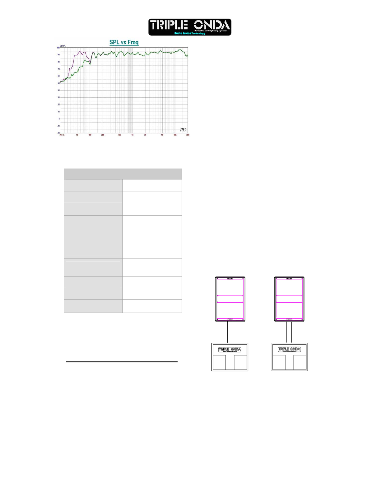
2.3. Technical features
Note:
- (*) 10 dB. Half space anechoic
- Specifications subjected to change without
p
revious notice.
3. MOUNTING AND PLACEMENT
For a proper installation of the acoustic cabinet
systems, it is strongly recommended to carefully
read the following advices.
3.1. Placement
The "Full Range" cabinets should be located in a
high position (between two or three meters),
slightly inclined to the audience. If the
loudspeakers are located too low, the listeners
at the end of the room will not receive enough
sound pressure level.
They may be located together, in cluster form,
one next to the other, taking advantage of their
trapezoidal shape. They may be also located
one on top of the other one, always trying to
maintain the slight inclined orientation that
guarantees the best coverage both in horizontal
or vertical.
It is strongly recommended to locate subwoofer
units on the floor as they can take advantage of
the so-called “floor-effect”, thus increasing the
response in the low frequencies.
If possible, place the subwoofers under the
same acoustic axis used for the satellites.
If the above option can not be carried out, then
they should be placed in an intermediate point
between the left and right channels.
3.2. Tripod use
The TOP.S 12A are equipped with a tripod
socket for use with Standard 35mm tripods.
Do not use the tripod on non-flat floors and be
careful not to raise the cabinets too high on the
tripod, as they may become unstable.
3.3. Live applications (mobile)
For a mobile application, whether it is an outdoor
or indoor installation, the common location is to
place the bass units (one or two per channel) on
each side of the stage or the dancefloor.
To obtain a clear and free-distortion
reproduction, it is advisable to place the mid-
high units on top of the low units keeping
between them an approximate height of two
meters. If such height cannot be achieved nor
maintained, it is advisable to use the classical
tripod for each mid-high cabinet and leave the
low units on the floor.
TOP.S 12A
Line Input XLR
(BALANCED) 1,5V-10 kΩ
Mains 230V +/- 10%
Full power
consumption 4 A
Components:
Woofer
Driver
1x12" Neo. Magnet
1" ¾ Titanium
Diaphragm
Directivity H/V 50º to 100º x 55º
Rotat.Horn
Frequency
Response(*)
48 Hz – 19 kHz
Maximum SPL (1m) 125 dB
Dimensions (H x W x
D) 627 x 412 x 401 mm
Weight 20,3 kg
TOP.S 12A 2009
4

3.4. Asymetrical and rotative
horns 50º
Nearfield
100º
TOP.S-12A models incorporate an asymmetrical
dispersion horn which will optimise coverage
either in horizontal or vertical position.
To rotate the horn, unscrewed the frontal grille,
and then, unscrewed the four fixing screws of
the horn. Rotate it 90 degrees taking care of the
wires. Screw the horn again and finally place the
frontal grille in its right position.
Good coverage of audiences often is a
conflicting combination of:
* wide coverage for the closest audience (short
throw)
* narrow coverage for distant areas ( long throw)
The asymmetrical dispersion horn coverage
varies from "short throw" to "long throw" along
the vertical axis (keeping a constant vertical
directivity). In conclusion, directivity feature of
(50º to 100º(H), 55º(V)) can be seen as if the
horn itself had "two" horizontal directivities
(audience coverage), which depend on the
distance. For short distances the horn should be
used with its "wide" dispersion (100º). For long
distances the horn should be used with its
"narrow" dispersion (50º).
We suggest to pay attention to the following
examples.
3.4.1. Vertical-Positioned Cabinets
(Hung and aiming to the audience)
We need wide coverage (100º) for the closest
listeners and narrow coverage for the distant
audience.
Difusor position:
.4.2. Horizontal-Positioned Cabinets
e need wide coverage (100º) for the closest
ifusor position
ARNING: e the "Nearfield" mark printed on
3
(Hung and aiming to the audience)
W
listeners and narrow coverage for the distant
audience.
D
50º
100º
SHORT THROW
LONG THROW
50º
100º Nearfield
W
The horns hav
the 100º horizontal coverage side.
100º
50º
LONG THROW
SHORT THROW
Near Field
TOP.S 12A 2009
5

50º
Nearfield
100º
3.4.3. Stage monitors
Case 1
We need wider coverage (100º) when
performers are close to the stage monitor than
when they move away from it (50º).
Case 2
We need wider coverage (100º) when
performers move away from the stage monitor
(long stages) than when they are close to it
(50º).
100º
50º
LONG THROW
SHORT THRO
W
3.5. Flying
Only experienced people should fly speaker
cabinets. Extreme care should be taken to
assure the load bearing capabilities of the
structures where the cabinets will be placed.
Hanging hardware (as chains, eyebolt, Lock
Pins...) should be regularly inspected and
replaced if in doubt.
WARNING!!! DO NOT SUSPEND THE
CABINETS FROM THE HANDLES!!!!
The TOP.S 12A model provide M8 flying points.
Their correct use will permit the flying in
horizontal or vertical position.
100º
50º
LONG THROW
SHORT THROW
14
3
50º
Nearfield
100º
2
Horizontal Flying
Points 1 and 2. Use point 3 to get the desired
inclination.
Vertical Flying
Points 1 and 4. Use point 3 to get the desired
inclination.
We offer as optional accessory the forged
eyebolt rigging M8 (ACR M8).
TOP.S 12A 2009
6

3.6. Accessories
ACR M8:
Forged eyebolt rigging for overhead installations.
SP/CR:
D:35mm/L:80cm Distance rod with M20 Thread.
SP/SX:
D:35mm/L:1.8m adjustable aluminium Tripod
stand.
COVER/FUNDA:
Protective Nylon cover.
FC-12A:
Flightcase for 2x TOPS12A units
4. TROUBLESHOOTING
No power
•Make sure that the cabinet is plug in.
•The Fuse is blown. Replace the fuse on fuse
holder with one of the same type. If it blows
again, take the unit to a service centre.
No sound
•Check that the mixer or sound source is
sending signal to the unit.
•Make sure that the VOLUME potentiometer is
well-positioned.
•Check that the cable from the sound source to
the units is connected correctly. Replace the
cable if defective.
•Make sure the output volume (gain) control on
the mixing console is turned up sufficiently to
drive the inputs of the speakers.
•Make sure the mixer does not have a Mute on.
Distorted sound
•The system is overloaded and has reached
maximum power. Turn down the mixer's output
or the channel's gain.
Poor bass performance
•Check the polarity of the connections between
the mixer and the cabinets. You may have the
positive and negative connections reversed at
one end of the cable, causing a loudspeaker to
be out-of-phase.
Noise and Hum
•Make sure all connections to the active unit are
in good conditions.
•Avoid the signal cables to be routed near AC
cables, power transformers, or EMI-inducing
devices.
•Check if there is any light dimmer on the same
AC circuit as the cabinet. Connect the sound
system to a different phase than the lights.
TOP.S 12A 2009
7
TOP.S 12A 2009
8
TRIPLE ONDA S.A
C/ Bobinadora 95
08302 MATARÓ (Barcelona-Spain)
Tel:+34-93741 28 28 FAX:+34-93 757 60 34
www. Tripleonda.com
This manual suits for next models
1
Table of contents
Other TRIPLE ONDA Speakers manuals


