Tripp Lite NetController B040-008-19 User manual

1
Owner’s Manual
Warranty
Registration:
register online today for a
chance to win a FREE Tripp Lite
product—www.tripplite.com/warranty
NetController™Rackmount
Console KVM Switches
Models: B040-008-19 and B040-016-19
Note: Follow these instructions and operating procedures to ensure correct performance and to prevent damage to this unit or to its connected devices.
Copyright © 2008 Tripp Lite. All rights reserved. All trademarks are the property of their respective owners.
Tripp Lite World Headquarters
1111 W. 35th Street, Chicago, IL 60609 USA
(773) 869-1234 • www.tripplite.com
1. Features 2
1.1 General Features 2
1.2 Package Contents 2
1.3 Hardware/Software Support 2
1.4 Cable Requirements 2
1.5 External Views 3
2. Installation 4
2.1 Rackmounting 4
2.2 Connecting PCs and Peripherals to a Single Switch 4
2.3 Daisy-Chaining 5
3. Operation 6
3.1 Control Interfaces 6
3.1.1 Push Buttons 6
3.1.2 Keyboard Hotkeys 6
3.1.3 On-Screen Display 7
3.2 OSD Main Menu 7
3.3 OSD Setup Menu 8
3.3.1 Auto Logout 8
3.3.2 OSD Timeout 8
3.3.3 Auto Scan Period 8
3.3.4 Title Bar 8
3.3.5 Hotkey 8
3.3.6 Password 8
3.3.7 Load Default 9
3.3.8 OSD Appearance 9
3.3.9 Upgrade Firmware 9
4. Technical Specifications 11
5. Warranty & Warranty Registration 11
Español 13
Français 25

2
1. Features
1.1 General Features
1.2 Package Contents
1.3 Hardware/Software Support
1.4 Cabling Requirements
• Built-in 19" display, keyboard and touch pad
• Connect up to 128 computers by daisy-chaining up to 8 levels of NetController KVM Switches*
• Allows for easy customization of ports by daisy-chaining any combination of NetController KVMs
• Standard 19” rackmount size
• OSD menu for intuitive operation and easy control
• USB and PS/2 keyboard and mouse support
• Password protection and auto-logout features
• Firmware upgradeable
• Robust metal case design ensures best EMI shielding and video quality
• Hot-swappable: disconnect and reconnect USB computers without rebooting
• Easy port selection via push buttons, keyboard hot keys or on-screen display (OSD)
* B040-Series NetController KVM Switches cannot be daisy-chained off of another KVM switch. They can only be used as the master (bank 1) KVM in a daisy-chained configuration.
• (1) B040-008-19 or B040-016-19 KVM Switch
• (1) 4-ft. Firmware Upgrade Cable—HD15 (F) to DB9 (F)
• (1) AC Power Cord
• (1) Owner’s Manual CD
• (1) Quick Start Guide
• Supports standard 5-button Microsoft®, Logitech® or comparable Mice
• Supports standard Microsoft, Logitech and comparable keyboards
• Supports a wide range of software platforms: Macintosh®, DOS, Windows 95/98/SE/NT/2000/ME/XP/Server2003/Vista, Unix®, Linux and BSD
• Superior video quality up to 1600 x 1200 @ 75Hz (for built-in monitor)
• Firmware Upgrade Cable—HD15 (F) to DB9 (M). Included.
• AC Power Cord. Included.
• Tripp Lite P780-Series USB PS/2 KVM Cable Kit—HD15 (M) to HD15 (M), MiniDIN6 (M), USB A (M) and USB A (F) to MiniDIN6 (M) Adapter.
Available in 6-ft., 10-ft. and 15-ft. lengths. Not included.
• Tripp Lite P781-series Daisy-Chain Cable—HD15 (M) to HD15 (F). Not included (required only when daisy-chaining KVMs).
• Daisy-Chain Terminator—HD15 (F). Not included (required only when daisy-chaining KVMs).
4-ft Firmware Upgrade Cable—Included P780-Series USB PS/2 KVM
Cable Kit —Not Included
Daisy-Chain Cable—Not Included Daisy-Chain Terminator—
Not Included

3
1. Features (continued)
1.5 External Views
Front View
1Upper Handle: Pull to slide the KVM Switch out; push to slide the KVM Switch in.
219” LCD Display: Built-in on-screen display (OSD) for convenient KVM Switch control, including port selection.
3OSD Push Buttons: Used to access the OSD Menu to adjust the LCD display.
4LED Indicators: The red LEDs will illuminate above each port with a connected computer that is running power through the console interface. If the connected
computer is powered off, the red LED will not be illuminated. The green LEDs will illuminate above the computer port that is currently selected as active.
5Port Selection Buttons: Push to directly select the active computer channel that can be controlled by the shared keyboard, touch pad and LCD display
6Keyboard
72-Button Touch Pad: Left button is left click, right is right click. Run your nger up or down the far right side of the touch pad to scroll up and down a screen.
8Slide Release: Mechanism to lock the drawer closed when the console is not in use. Prevents it from accidentally sliding open. To slide the console out, you
must rst release it by moving the tab sideways.
9Rackmounting Brackets: There are rackmount brackets to secure the chassis to a system rack located at each corner of the unit.
10 Railway Release Tabs: When the drawer is completely pulled out to the end, the railway system will lock. Push the release tabs on both sides to release the
drawer so that it can be pushed back in.
2
1
3
4
5
6
7
9
10
8
8
100-240V AC 50/60Hz
DAISY-CHAIN OUT
FIRMWARE UPGRADE
76 54 32
16 15 14 13 12 11 10 9
1
NetController™ 16-PORT CONSOLE KVM SWITCH MODEL: B040-016-19
8
100-240V AC 50/60Hz
DAISY-CHAIN OUT
FIRMWARE UPGRADE
76 54 32
16 15 14 13 12 11 10 9
1
NetController™ 16-PORT CONSOLE KVM SWITCH MODEL: B040-016-19
Rear View
Figure 1-2: B040-008-19 Rear Panel
Figure 1-3: B040-016-19 Rear Panel
1Power Dongle: The power dongle should receive electricity from the included AC power cord.
2USB Port: The USB port is available if you want to use a separate keyboard or mouse.
3PC Ports: The PC port is a HD15 (F) connector integrated with USB and PS/2 keyboard, mouse and video. To connect a computer to the PC port, you
will need one of Tripp Lite’s P780-Series USB PS/2 KVM Cable Kits. Not included.
4Firmware Upgrade Port: This port is used during the rmware upgrade process (see 3.3.9 Upgrade Firmware on pg. 11).
5Daisy-Chain OUT Port: The daisy-chain OUT port is a HD15 (F) connector which provides daisy-chaining downstream to a B042-Series KVM Switch.
3
34 1
5
5
4 12
2
Figure 1-1: NetController KVM Front Panel

4
2. Installation
2.1 Rackmounting
Rackmounting Instructions
Ambient Operating Temperature
The ambient operating temperature in the rack may be an issue and is dependent upon the rack load and ventilation. When installing in a closed or
multi-unit rack assembly, make sure that the temperature will not exceed the maximum rated ambient temperature. (32º to 104º F)
Airflow
Ensure that the airow within the rack is not compromised.
Circuit Overloading
When connecting the equipment to the supply circuit, consider the effect that overloading of circuits might have on over-current protection and supply wiring.
Reliable grounding of rack-mounted equipment should be maintained.
To protect against circuit overloading you should connect your NetController KVM and attached computers/servers to a Tripp Lite SmartPro®or
SmartOnline® UPS System.
The NetController KVM Switch is designed for mounting in a 1U rack system. For convenience, a rack mounting kit is included with your KVM
for quick installation. The various mounting options are explained in the sections that follow.
Standard Rackmounting
The standard rackmounting brackets that come attached to the
KVM Switch allow the unit to be installed in standard 1U racks
by a single individual.
Slide out the rear mounting brackets from the console
and mount both brackets (separate from the console) to the
inside rear of a standard 1U rack system using user-supplied
screws.
Take the console and gently slide it into the two rear-
mounted brackets in the rack and secure the console in place
by inserting user-supplied screws.
2-Post Rackmounting
The NetController KVM Switch can also be mounted in a 2-post rack installation using the optional 2-Post Rackmount Kit (model #: B019-000). The
mounting hardware allows for the console to be opened with the drawer in any position. Heavy-duty 14-gauge steel provides stability and prevents
the console frame from twisting. See the B019-000 instructional manual for detailed mounting instructions.
11
2
2
2.2 Connecting PCs and Peripherals to a Single Switch
Step 1: Connect the included AC power cord to the KVM Switch to power it on.
Step 2: Connect each computer to the KVM Switch using a P780-Series Tripp Lite USB PS/2 KVM Cable Kit. Not included.
The KVM Switch is now ready to operate as soon as you turn on any of the attached computers.
Note: When you are connecting a PS/2 computer, it is required that the NetController KVM Switch is connected and powered on before starting your computers.

5
2. Installation (continued)
2.3 Daisy-Chaining
Warning! The total length of daisy-chain cabling from the master KVM switch to the last KVM switch in a daisy-chain installation (regardless of the
number of levels) must not exceed 16 ft. (5 m). If the total length of daisy-chain cabling exceeds 16 ft. (5 m), the installation will not function properly.
To maximize the number of connected computers, multiple NetController KVM Switches can be daisy-chained together to connect up to a total of
128 computers. The NetController KVM Switches that are to be daisy-chained do not have to be of the same port capacity. You can daisy-chain any
combination of NetController KVM Switches to scale the port capacity with more exibility. KVM controls can then be extended to groups of computers
connected on the daisy-chain of NetController KVM Switches.
Note: B040-Series NetController KVM Switches cannot be daisy-chained off of another KVM switch. They can only be used as the master
(bank 1) KVM in a daisy-chained configuration.
Daisy-chain Multiple KVM Switches
Step 1: Connect the AC power cord to the master KVM Switch and plug it in to a power source.
Step 2: Use daisy-chain cable—HD15 (M) to HD15 (F)—to connect the daisy-chain OUT port of the master KVM switch to the
daisy-chain IN port of the second (downstream) NetController Switch.* Then connect the AC power cord to the second KVM Switch.
Step 3: Follow the same procedure for any additional KVM Switches you would like to attach, creating a daisy-chain up to 8 KVM Switches.
Step 4: After you have set up the Daisy-Chain of KVM Switches, plug the daisy-chain terminator into the daisy-chain OUT port of the last
KVM Switch.
Step 5: Connect each computer to the KVM Switches in your daisy-chain using a P780 series Tripp Lite USB PS/2 KVM Cable Kit. Not included.
Step 6: The KVM Switches are now ready to operate as soon as you turn on any of the attached computers.
Note: When you are connecting a PS/2 computer, it is required that the NetController KVM Switch is connected and powered on before starting your computer.
* A Tripp Lite P781-series daisy-chain cable is required (sold separately).
Figure 2: Daisy-Chain Diagram
P780 series
cables
P780 series
cable kit
Host computer not needed at any other time.
.
P781-series daisy-chain cables
BANK 8
Warning! Total daisy-chain cabling distance from the master KVM switch to the last KVM switch must not exceed 16 ft. (5 m).

6
3. Operation
3.1 Control Interfaces
There are three ways to operate your NetController KVM Switch—Push buttons, Keyboard Hotkeys or the OSD Menu. The operation of these three control
methods is detailed below.
3.1.1 Push Buttons
The push buttons are used to directly select the active computer channel that can be controlled by the shared keyboard, mouse and monitor. Pressing a front-
panel button during normal operation will cause the corresponding channel to be selected.
3.1.2 Keyboard Hotkeys
Hotkeys are a convenient and quick way to operate the KVM Switch. Most of the hotkey control commands are preceded by two consecutive Scroll Lock
keystrokes, followed by a specic command key or key sequence:
Hotkey control command** = ScrLk* + ScrLk* + Command Key/Sequence
* User-Denable hotkey via the OSD Setup Menu. You have the option of using ScrLk, Caps Lock, Num Lock (OSD will say ‘Number’ instead of ‘Num Lock.’) or F12.
** Each key in a Hotkey Command must be pressed within 2 seconds of the previous key to allow the command to take place.
In most cases, it will take at least three keystrokes to complete a command. In certain cases, commands may require up to 6 strokes (such as when selecting
specic bank and port numbers for the active channel).
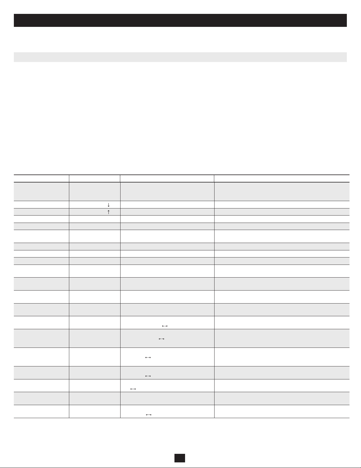
All the available hotkey commands and OSD Menu options are summarized in the following table for your convenience.
This chapter provides general guidelines for KVM Switch operation. It is strongly recommended that you read this chapter in advance of operating your
NetController KVM Switch.
Command Hotkey Sequence2OSD Control3Description
Select Computer ScrLk5+ ScrLk5 + ab +
xy (ab= 2-Digit Bank #
xy= 2-Digit Channel #)1
Highlight the desired computer and hit the
Enter key
Activates a desired computer to be accessed via the console
Next Lower Channel ScrLk5+ ScrLk5+ — Selects the next lower connected channel on the active KVM Switch
Next Higher Channel ScrLk5+ ScrLk5+ — Selects the next higher connected channel on the active KVM Switch
Next Lower Bank ScrLk5+ ScrLk5 + PgUp Hit Page Up button when in OSD Main Menu Select the next lower KVM Switch in a Daisy-Chain
Next Higher Bank ScrLk5+ ScrLk5 + PgDn Hit Page Down when in OSD Main Menu Select the next higher KVM Switch in a Daisy-Chain
Beep On/Off ScrLk5+ ScrLk5 + B — Turns the beep sound on/off when Auto Scanning and when
hitting hotkeys
Auto Scan ScrLk5+ ScrLk5+ S —Starts an Auto Scan of all the connected computers
Stop Autoscan Any key —Stops an Auto Scan of all the connected computers
Title Bar On/Off ScrLk5+ ScrLk5+ T — Turns the Title Bar On/Off.
Reset Console
Mouse & Keyboard
ScrLk5 + ScrLk5 + End — Resets Console Mouse & Keyboard in the unlikely event of a lockup
Show OSD Menu ScrLk5+ ScrLk5+
(Space Bar)
— Opens up the OSD Main Menu
Change Computer Name — Highlight the desired computer in the OSD
Main Menu, hit Insert to change name
Changes the computer’s name from the default (PC01, PC02, etc) of all
daisy-chained KVM switches to a user-dened name. 8 character limit
Load Default — In OSD Setup Menu select Load Default and
hit the Enter Key
Restores all settings (Auto Logout, OSD Timeout, etc.) of all daisy-
chained KVM switches to the default settings. Does not affect password
OSD Appearance — In OSD Setup Menu highlight OSD
Appearance and use Keys to choose Yes/No
Species if you want to keep/hide the OSD
Menu after a Port Switching Operation
Auto Scan Period
(00 – 95 seconds)
— In OSD Setup Menu highlight Auto Scan
Period and use the keys to choose time
interval
Species a time interval for the Auto Scan to switch between
computers. Auto Scan set to 10 seconds by default. 00= Disabled.
Auto Logout Timeout
(00-99 minutes)
— In OSD Setup Menu highlight Auto Logout
and use the keys to choose time interval
Species the amount of time that must pass without keyboard
activity before KVM logs off. This requires password to be entered
to access KVM. Auto Logout is disabled by default: 00= Disabled.
OSD Menu Timeout
(00-95 seconds)
— In OSD Setup Menu highlight OSD Timeout
and use the keys to choose time interval
Species the amount of time with no activity before the OSD Menu
turns off. OSD Menu Timeout defaults at 30 seconds.
Title Bar Position — In OSD Setup Menu highlight Title Bar;
use keys to choose Left, Right or Disable
Displays the Title Bar on the Left or Right side of the monitor screen
or disables it.
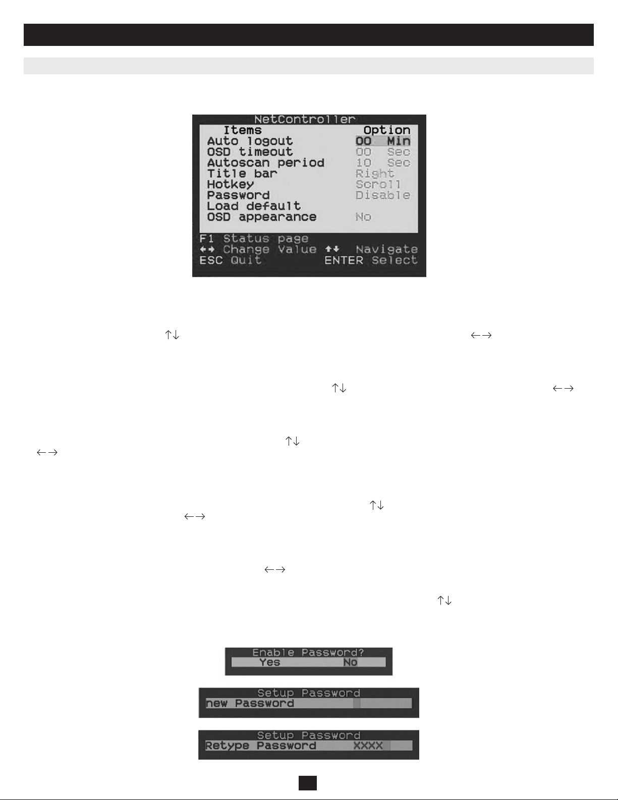
Password4— In OSD Setup Menu highlight Password and
hit the Enter key. Follow steps to set password.
Enables/disables the password for the B040-004, -008 or -016 KVM
switch. User-denable password has an 8-character limit
Define Hotkey
Preceding Sequence
— In OSD Setup Menu highlight the Hotkey
Option; use keys to select desired Hotkey
Selects a Hotkey preceding sequence of Scroll Lock, Caps Lock,
Num Lock or F12
1) a, b, x and y each denote a number key. (ab) = 01 – 08 (xy) = 01 – 016. When using an individual KVM switch, bank # will be 01
2) Each Hotkey must be pressed within 2 seconds of the preceding Hotkey for the command to take place.
3) Activate OSD menu, using ScrLk + ScrLk + (Space Bar). More detailed OSD Operation instructions are provided in this user’s guide. When OSD Menu is active, mouse will be locked until the OSD
Menu is off.
4) The password has an 8-character limit. If you forget your password and can’t access your KVM, contact Tripp Lite Tech Support at (773) 869-1234
5) User-Denable Hotkey Preceding sequence. Choose between Scroll Lock, Caps Lock, Num Lock and F12

7
3. Operation (continued)
3.1.3 On-Screen Display
To activate the OSD Menu, use the hotkey sequence: ScrLk + ScrLk + (Space Bar)
OSD (On-Screen Display) is a menu that is superimposed on your screen. In the OSD Menu, you will see a listing of the available banks and channels for
selection and the currently online status of each channel. You can use the OSD to control the KVM switch with more convenient and intuitive menu-driven
operation. The OSD menu also allows you to rename your computer (up to 8 characters), which lets you nd a computer by its name instead of port number.
It also allows you to password-protect your KVM switch system.
Note: While OSD is activated, all the push buttons and mouse activity will be made inactive.
Figure 3-1: OSD Main Menu
The computer name that is followed by a human symbol means that it is currently the active channel you can monitor on your
local console now.
The computer name that is followed by a solar symbol indicates that it is currently connected to the KVM Switch via PS/2 interface and feeding power
to the KVM switch.
The computer name that is followed by a USB symbol indicates that it is connected to the KVM switch via USB interface and feeding power to the
KVM switch.
Computers that do not show any symbol are either not connected or are not powered on.
The computer name that is illuminated by a background color indicates that it is currently in focus, and you can perform OSD operation on it using your
keyboard.
Navigating through the Computers in the OSD Main Menu
Use the keys to highlight the desired computer. To access different KVMs in a Daisy-Chain, use the ‘Page Up’ and ‘Page Down’ keys to scroll
to the desired KVM (Bank).
Selecting a Computer as the Active computer on your Console
Highlight the desired computer by using the keys and hit the ‘Enter’ key. To access different KVMs in a Daisy-Chain, use the ‘Page Up’ and
‘Page Down’ keys to scroll to the desired KVM (Bank).
Editing a Computer
To change the Computers name in the OSD, use the keys to highlight the desired computer and hit the ‘Insert’ key to edit. To access different KVMs
in a Daisy-Chain, use the ‘Page Up’ and ‘Page Down’ keys to scroll to the desired KVM (Bank).
Exiting the OSD Menu
Hit the ‘Esc’ key
Logout from the KVM Switch
Hit the ‘F10’ key
3.2 OSD Main Menu

8
3. Operation (continued)
Hit the F1 Key when inside the OSD Main Menu to access the OSD Setup Menu
Figure 3-2: OSD Setup Menu
3.3.1 Auto Logout
Specify time for Auto Logout. Use the keys to navigate to the Auto Logout option in the OSD Setup Menu and use the keys to change the time
interval. Hit the ‘Enter’ key to conrm the change. The Auto Logout defaults to 00 minutes and can be increased/decreased by intervals of 1, between 1 and
99. Once logged out, you will need to enter your password to access the KVM switch.
3.3.2 OSD Timeout
Specify duration for OSD Menu to stay on screen with no keyboard activity. Use the keys to navigate to the OSD Timeout option and use the keys
to change the time interval. Hit the ‘Enter’ key to conrm the change. The OSD Menu Timeout defaults at 30 seconds and can be increased/decreased by
intervals of 5, between 00 and 95. 00 means the OSD Menu Timeout is disabled.
3.3.3. Auto Scan Period
Specify the time interval between computers during Auto Scan. Use the keys to navigate to the Auto Scan Period option in the OSD Setup Menu and use
the keys to change the time interval. Hit the ‘Enter’ key to conrm the change. The Auto Scan period defaults to 10 seconds and can be increased/de-
creased by intervals of 5, between 5 and 95.
3.3.4 Title Bar
Determine the location of the Title Bar or disable it. The Title Bar species which computer you are using and defaults to the left side of your screen. You
can select whether the OSD Title Bar will appear on the left or right side of the screen. Use the keys to navigate to the OSD Title Bar option in the OSD
Setup Menu and hit the ‘Enter’ key. Use the keys to change where the Title Bar will appear.
3.3.5 Hotkey
Specify the Hotkey preceding sequence for all Hotkey commands. The Hotkey option allows you to choose among 4 keys to use as the initial hotkey. You
can use Scroll Lock, Caps Lock, Num Lock (Num Lock will be described as Number) or F12. To change the Hotkey Preceding Sequence, go to the OSD
Setup Menu, highlight Hotkey, select the desired hotkey using the keys and hit the ‘Enter’ key to conrm the change.
3.3.6 Password
Specify password for access to the KVM switch. (Note: The Setup Password option defaults to disabled.) Use the keys to navigate to the Setup Pass-
word option in the OSD Setup Menu and hit the ‘Enter’ key to select. Select to Enable or Disable Password Protection. Once enabled, you will be required to
enter your password to access the KVM switch. Password defaults at ‘admin.’ To change the password conguration, you must provide the current password
before making changes. If you forget your password and cannot access your KVM, contact Tripp Lite Tech Support at (773) 869-1234.
3.3 OSD Setup Menu
Figure 3-3: Password Setup Prompts

9
3. Operation (continued)
3.3.7 Load Default
Return a selected KVM switch to factory default settings (e.g., computer names, Auto Scan time, Auto Logout, etc.). This option will not change or disable
password settings, ensuring the security of your KVM switch. Navigate to Load Default using keys and hit ‘Enter’.
3.3.8 OSD Appearance
Species if you want to keep or hide the OSD Menu after port switching operation. In the OSD Setup Menu, highlight OSD Appearance and use to
choose Yes/No.
3.3.9 Upgrade Firmware
All rmware upgrades for the B042-004, -008 and -016 KVM Switches will be available in the Support Section of www.tripplite.com. (If there are no updates
posted, there are none currently available.) Before downloading the rmware les, verify that the rmware version on the website is more current that that of
your KVM switch. You can nd your KVM switches rmware version by navigating to the Status Page in the OSD. You can also use the Firmware Upgrade
Utility to check your rmware version. (See below) To perform a rmware upgrade on your B042-Series KVM Switch, follow these instructions.
Step 1: Using the provided Firmware Upgrade Cable, connect a standalone computer (one not already connected to the KVM Switches Server Port) to the
KVM Switch. If you have multiple KVM Switches daisy-chained together, connect the Firmware Upgrade Cable to the Master KVM Switch (the
rst KVM in the daisy-chain). All KVM switches daisy-chained from the Master KVM switch will be upgraded simultaneously.
Step 2: Go to the Support section of www.tripplite.com and download the rmware upgrade utility and upgrade le.
Step 3: Before upgrading the rmware on your NetController KVM Switch, disable all running programs (anti-virus, system monitoring, etc.) on the
standalone computer you are using to perform the upgrade. These programs may prevent the rmware upgrade from completing successfully.
Step 4: Locate the .exe le you just downloaded and double-click on it. The KVM Upgrade Utility screen will open.
Figure 3-5: Firmware Select File Window

10
3. Operation (continued)
Step 5: Click the Select File button and nd the rmware upgrade le that you just downloaded.
Step 6: If you have not yet veried your KVM Switches rmware version number via the OSD Status page, click the Check Version button. This will
compare your KVM Switches rmware to the rmware upgrade le you just downloaded. If your KVM has more recent rmware, the Firmware
Upgrade Utility will ask you if you wish to continue.
If so, click the Upgrade button to start the upgrade. If not, close out of the Firmware Upgrade Utility. If your KVM Switch has older rmware
than the downloaded le, click on the Upgrade button to start the upgrade. (Upon clicking the Upgrade button, you will be notied that the video,
keyboard and mouse will be locked up during the upgrade process. Click yes to continue or no to exit.)
Step 7: During the rmware upgrade process, your KVM switch console will go blank and you will not be able to use the keyboard or mouse. Functionality
will return upon rmware completion. The Firmware Upgrade Utility will notify you if the update was successful or not. If the upgrade fails, see
the Troubleshooting section below.
Firmware Upgrade Troubleshooting
If the rmware upgrade fails due to timeout, stalls at any point for a long period of time or fails due to power outage, check to make sure all running
programs (anti-virus, system monitoring, etc.) are turned off. When you have determined all programs are disabled, unplug and re-plug the rmware
upgrade cable and try the upgrade procedure again.
If you nd that your keyboard and mouse are no longer working during a rmware upgrade failure, temporarily connect them to the host PC until you can
nish the upgrade. Once completed, your KVM console should again be working properly.
If you nd you have continued problems, please contact Tripp Lite Technical Support at (773) 869-1234 for assistance.
Figure 3-6: Firmware Comparison Window
Figure 3-7: Firmware Upgrade Window Figure 3-8: Firmware CRC Error

11
4.Technical Specifications
5. Warranty & Warranty Registration
1-Year Limited Warranty
TRIPP LITE warrants its products to be free from defects in materials and workmanship for a period of one (1) year from the date of initial purchase. TRIPP LITE’s obligation under this warranty
is limited to repairing or replacing (at its sole option) any such defective products. To obtain service under this warranty, you must obtain a Returned Material Authorization (RMA) number from
TRIPP LITE or an authorized TRIPP LITE service center. Products must bereturned to TRIPP LITE or an authorized TRIPP LITE service center with transportation charges prepaid and must be
accompanied by a brief description of the problem encountered and proof of date and place of purchase. This warranty does not apply to equipment, which has been damaged by accident, negligence or
misapplication or has been altered or modied in any way.
EXCEPT AS PROVIDED HEREIN, TRIPP LITE MAKES NO WARRANTIES, EXPRESS OR IMPLIED, INCLUDING WARRANTIES OF MERCHANTABILITY AND FITNESS FOR A
PARTICULAR PURPOSE. Some states do not permit limitation or exclusion of implied warranties; therefore, the aforesaid limitation(s) or exclusion(s) may not apply to the purchaser.
EXCEPT AS PROVIDED ABOVE, IN NO EVENT WILL TRIPP LITE BE LIABLE FOR DIRECT, INDIRECT, SPECIAL, INCIDENTAL OR CONSEQUENTIAL DAMAGES ARISING OUT
OF THE USE OF THIS PRODUCT, EVEN IF ADVISED OF THE POSSIBILITY OF SUCH DAMAGE. Specically, TRIPP LITE is not liable for any costs, such as lost prots or revenue, loss of
equipment, loss of use of equipment, loss of software, loss of data, costs of substitutes, claims by third parties, or otherwise. Visit www.tripplite.com/warranty today to register the warranty for your new
Tripp Lite product. You’ll be automatically
Warranty Registration
Visit www.tripplite.com/warranty today to register the warranty for your new Tripp Lite product. You’ll be automatically entered into a drawing for a chance to win a FREE Tripp Lite product!*
* No purchase necessary. Void where prohibited. Some restrictions apply. See website for details.
Use of this equipment in life support applications where failure of this equipment can reasonably be expected to cause the failure of the life support equipment or to signicantly affect its safety or
effectiveness is not recommended. Do not use this equipment in the presence of a ammable anesthetic mixture with air, oxygen or nitrous oxide.
The policy of Tripp Lite is one of continuous improvement. Specications are subject to change without notice.
Made in China.
PC Connections 8 PC Ports (B040-008-19)
16 PC Ports (B040-016-19)
PC Port Connector
(All female type)
HD15 (F)—integrated with USB and PS/2 Keyboard, Mouse and Video
Daisy-Chain Port Connectors HD15 (M)—Firmware Upgrade
HD15 (F)—Daisy-Chain Out/Terminator
PC Selection On-Screen Display (OSD) Menu, Hotkeys or Push Buttons
LED Indicators 8 Green; 8 Red (B040-008-19)
16 Green; 16 Red (B040-016-19)
On Screen Display (OSD) Yes
Auto Scan Period Programmable from 1-99 seconds
Keyboard Emulation PS/2 and USB
Mouse Emulation PS/2 and USB
Resolution 1600 x 1260@75 Hz
Daisy-Chain Levels 8 Levels
MAX Daisy-Chain Cabling Distance 16 ft. (5 m) from rst to last KVM
MAX PC Connection 128 (8 B042-Series NetController KVM Switches)
Housing Metal
Operation Temperature 32° — 104°F
Storage Temperature -13°F — 140°F
Humidity 20%— 90% non-condensing
Size 19" Rackmount
Certications CE, FCC, TUV, CTUV, NOM, ROHS

12
1111 W. 35th Street, Chicago, IL 60609 (É-U)
(773) 869-1234 • www.tripplite.com

13
Manual del Propietario
Multiplexores KVM NetController™
de Consola Rackmount
Modelos: B040-008-19 y B040-016-19
Nota: Para garantizar un funcionamiento correcto e impedir que se dañe la unidad o sus dispositivos conectados, siga estas instrucciones y procedimientos operativos.
Copyright © 2008 Tripp Lite. Todos los derechos reservados. Todas las marcas comerciales son de propiedad de sus respectivos dueños.
Casa Matriz de Tripp Lite
1111 W. 35th Street, Chicago, IL 60609 EE.UU.(773) 869-1234 • www.tripplite.com
1. Características 14
1.1 Características Generales 14
1.2 Contenidos del Embalaje 14
1.3 Compatibilidades de Hardware y Software 14
1.4 Cables Necesarios 14
1.5 Vistas Externas 15
2. Instalación 16
2.1 Rackmount 16
2.2 Conexión de las Computadoras y Periféricos a un
Único Multiplexor 16
2.3 Encadenamiento 17
3. Operación 18
3.1 Interfaces de Control 18
3.1.1 Botones Interruptores 18
3.1.2 Teclas de Acceso Rápido del Teclado 18
3.1.3 Menú en Pantalla 19
3.2 Menú Principal en Pantalla 19
3.3 Menú de Configuración en Pantalla 20
3.3.1 Auto Logout (Cierre de Sesión Automático) 20
3.3.2 OSD Timeout (Intervalo de Espera del Menú
en Pantalla) 20
3.3.3 Auto Scan Period (Período de Escaneo
Automático) 20
3.3.4 Title Bar (Barra de Título) 20
3.3.5 Hotkey (Tecla de Acceso Rápido) 20
3.3.6 Password (Contraseña) 20
3.3.7 Load Default (Cargar Valores
Predeterminados) 21
3.3.8 OSD Appearance (Apariencia del Menú en
Pantalla) 21
3.3.9 Actualización del Firmware 21
4. Especificaciones Técnicas 23
5. Garantía 23
English 1
Francés 25

14
1. Características
1.1 Características Generales
1.2 Contenidos del Embalaje
1.3 Compatibilidades de Hardware y Software
1.4 Cables Necesarios
• Pantalla de 19" integrada, teclado y touchpad
• Conecta hasta 128 computadoras encadenando hasta 8 niveles de multiplexores KVM NetController*
• Permite personalizar fácilmente los puertos encadenando una combinación de multiplexores KVM NetController
• Tamaño rackmount estándar de 19”
• Menú en pantalla para una operación intuitiva y control fácil
• Admite teclado y mouse USB y PS/2
• Recursos de protección mediante contraseña y cierre de sesión automático
• Firmware actualizable
• Posee un diseño gabinete metálico resistente que garantiza el mejor blindaje EMI y calidad de video
• Reemplazo mientras el equipo se encuentra en operación (hot-swappable): desconecte y vuelva a conectar los servidores de base sin tener que reinicializar
• Fácil selección de puertos mediante botones interruptores, teclas de acceso rápido del teclado o por menú en pantalla
* Los multiplexores KVM NetController serie B040 no pueden desencadenarse de otro multiplexor KVM. Sólo pueden utilizarse como el KVM maestro (banco 1) en una configuración en cadena.
• (1) Multiplexor KVM B040-008-19 o B040-016-19
• (1) Cable para actualizar rmware de 4 pies (1.2m) —HD15 (F) a DB9 (F)
• (1) Cable de alimentación CA
• (1) CD de Manual del Propietario
• (1) Guía Rápida de Inicio
• Admite mouse Microsoft®, Logitech® u otros comparables estándares de 5 botones
• Admite teclados Microsoft, Logitech y otros comparables estándares
• Admite una amplia variedad de plataformas de software: Macintosh®, DOS, Windows 95/98/SE/NT/2000/ME/XP/Server2003/Vista, Unix®, Linux y BSD
• Calidad de video superior de hasta 1600 x 1200 a 75Hz (para monitor incorporado)
• Cable para actualización del rmware—HD15 (F) a DB9 (M). Incluido.
• Cable de alimentación CA. Incluido.
• Juego de cables KVM USB PS/2 serie P780 Tripp Lite—HD15 (M) a HD15 (M), MiniDIN6 (M), USB A (M) y USB A (F) a adaptador MiniDIN6 (M).
Disponible en longitudes de 6 pies (1.8m), 10 pies (3.0m) y 15 pies (4.6m). No vienen incluidos.
• Cable para encadenamiento serie P781 Tripp Lite —HD15 (M) a HD15 (F). No viene incluido (se necesita solo cuando se encadenan KVM).
• Terminador de encadenamiento—HD15 (F). No viene incluido (se necesita solo cuando se encadenan KVM).
Cable para Actualización del Firmware
de 4 pies (1.2m) —Incluido
Juego de Cables KVM USB PS/2
Serie P780 —No se incluye
Cable para Encadenamiento—
No viene incluido
Terminador de Encadenamiento—
No incluido

15
1. Características (continuación)
1.5 Vistas Externas
Vista Frontal
1Manija Superior: Tírela para deslizar y sacar el multiplexor KVM; empújela para deslizar y colocar el multiplexor KVM.
2Pantalla LCD de 19": Menú en pantalla integrado para un conveniente control del multiplexor KVM, incluyendo la selección del puerto.
3Botones Interruptores de Menú en Pantalla: Se utilizan para acceder al menú en pantalla y poder ajustar la pantalla LCD.
4LED Indicadores: Los LED rojo se iluminan sobre cada puerto que tenga una computadora conectada que esté funcionando con corriente a través de la interfaz
de la consola. Si la computadora conectada no recibe corriente, el LED rojo no se iluminará. Los LED verde se iluminarán sobre el puerto de la computadora
que esté seleccionado actualmente como activo.
5Botones para Selección de Puertos: Presiónelos para seleccionar directamente el canal de la computadora activa que puede controlarse mediante el teclado, el
touchpad y la pantalla LCD compartidos
6Teclado
7Touchpad de 2 Botones: El botón izquierdo representa el botón izquierdo del mouse, y el botón derecho, el derecho del mouse. Pase el dedo hacia arriba o
hacia abajo en el extremo derecho del touchpad para desplazarse hacia arriba y hacia abajo de una pantalla.
8Desenganche Deslizante: Mecanismo para bloquear el cajón cerrado cuando no se está usando la consola. Impide que se deslice accidentalmente y se abra. Para
deslizar y sacar la consola, primero debe desengancharla moviendo esta pestaña hacia el lado.
9Soportes para Rackmount: Existen soportes para rackmount cuyo n es asegurar el chasis a un rack de sistema situado en cada esquina de la unidad.
10
Pestañas de Liberación de Riel: Cuando el cajón esta completamente sacado hasta el nal, el sistema de riel se bloqueará. Empuje las pestañas de liberación en
ambos lados para soltar el cajón de manera que pueda volver a empujarse para meterse.
2
1
3
4
5
6
7
9
10
8
8
100-240V AC 50/60Hz
DAISY-CHAIN OUT
FIRMWARE UPGRADE
76 54 32
16 15 14 13 12 11 10 9
1
NetController™ 16-PORT CONSOLE KVM SWITCH MODEL: B040-016-19
8
100-240V AC 50/60Hz
DAISY-CHAIN OUT
FIRMWARE UPGRADE
76 54 32
16 15 14 13 12 11 10 9
1
NetController™ 16-PORT CONSOLE KVM SWITCH MODEL: B040-016-19
Vista Posterior
Figura 1-2: Panel Posterior de B040-008-19
Figura 1-3: Panel Posterior de B040-016-19
1Llave de Alimentación: La llave de alimentación debe recibir electricidad desde el cordón de alimentación CA que viene incluido.
2Puerto USB: El puerto USB se encuentra disponible en caso de que desee usar un teclado o mouse aparte.
3Puertos para Computadora: El puerto para computadora es un conector HD15 (F) que viene integrado con un teclado, mouse y video USB y PS/2.
Para conectar una computadora al puerto para computadora, usted necesitará uno de los juegos de cables KVM USB PS/2 serie P780 de Tripp Lite. No
se incluyen.
4Puerto de Actualización del Firmware: Este puerto se utiliza durante el proceso de actualización del rmware (vea 3.3.9 Actualización del Firmware
en la pág. 11).
5Puerto de SALIDA de Encadenamiento: El puerto de SALIDA de encadenamiento es un conector HD15 (F) que proporciona encadenamiento en
descenso hasta un multiplexor KVM serie B042.
3
34 1
5
5
4 12
2
Figura 1-1: Panel Frontal de KVM NetController

16
2. Instalación
2.1 Rackmount
Instrucciones para Rackmount
Temperatura de Operación Ambiente
La temperatura de operación ambiente en el rack puede ser un problema y depende de la carga del rack y su ventilación. Cuando se instala en un rack
cerrado o de varias unidades, asegúrese de que la temperatura no supere el valor máximo nominal ambiental. (32º a 104º F) (0° a 40°C)
Flujo de Aire
Asegúrese de que no se obstruya el ujo de aire dentro del rack.
Sobrecarga del Circuito
Cuando conecte el equipo al circuito de suministro del circuito, considere el efecto que podría tener la sobrecarga de circuitos en la protección contra
sobrecorriente y cableado de suministro.
Debe mantenerse una conexión a tierra conable del equipo en el rack.Para brindar protección contra sobrecarga de circuitos, debe conectar su KVM
NetController y las computadoras/servidores conectados a un sistema UPS Tripp Lite SmartPro® o SmartOnline®.
El multiplexor KVM NetController está diseñado para rack de 1U. Para su conveniencia, con su multiplexor KVM se incluye un juego para montaje en rack.
En las secciones a continuación se explican las diversas opciones de montaje.
Rackmount Estándar
Los soportes para rackmount estándares que vienen instalados en el
multiplexor KVM permiten que la unidad pueda ser instalada por una
sola persona en racks de 1U estándares.
Deslice y saque los soportes de montaje posteriores de la consola
y monte ambos soportes (separados de la consola) en la parte
posteriorinterna de un sistema de rack estándar de 1U utilizando
tornillos provistospor el usuario.
Tome la consola y deslícela suavemente en los dos soportes montados
en la parte posterior del rack y asegure la consola en su lugar
insertando los tornillos suministrados por el usuario.
Rackmount de 2 Postes
El multiplexor KVM NetController también puede montarse en un rack de 2 postes usando el juego para rackmount opcional de 2 postes (modelo N°:
B019-000). Los accesorios de instalación permiten que la consola pueda operarse con el cajón en cualquier posición. El acero de calibre 14 de alta
resistencia proporciona estabilidad e impide que la estructura del rack gire. Consulte el manual de instrucciones de B019-000 para obtener instrucciones
detalladas de montaje.
11
2
2
2.2 Conexión de las Computadoras y Periféricos a un Único Multiplexor
Paso 1: Conecte cable de alimentación CA al multiplexor KVM para encenderlo.
Paso 2: Conecte cada computadora al multiplexor KVM utilizando un juego de cables KVM USB PS/2 serie P780 de Tripp Lite. No se incluyen.
El multiplexor KVM ahora está listo para operar apenas encienda algunas de las computadoras conectadas.
Nota: Cuando conecte una computadora PS/2, es necesario que el multiplexor KVM NetController esté conectado y encendido antes de arrancar sus computadoras.

17
2. Instalación (continuación)
2.3 Encadenamiento
¡Advertencia! La longitud total del cableado para encadenamiento desde el multiplexor KVM maestro hasta el último multiplexor KVM en una
instalación encadenada (sin importar la cantidad de niveles) no debe superar los 16 pies (5 m). Si el largo total del cableado del encadenamiento es
mayor a 16 pies (5 m), la instalación no funcionará adecuadamente.
Para maximizar la cantidad de computadoras conectadas, pueden encadenarse varios multiplexores KVM NetController para conectar hasta un total
de 128 computadoras. Los multiplexores KVM NetController que van a encadenarse no tienen que tener la misma capacidad de puertos. Usted puede
encadenar cualquier combinación de multiplexores KVM NetController para escalar con mayor exibilidad la capacidad del puerto. Entonces, los
controles del KVM pueden extenderse a grupos de computadoras conectadas en el encadenamiento de multiplexores NetController.
Nota: Los multiplexores KVM NetController serie B040 no pueden desencadenarse de otro multiplexor KVM. Sólo pueden utilizarse como el
KVM maestro (banco 1) en una configuración en cadena.
Encadenamiento de Varios Multiplexores KVM
Paso 1: Conecte el cable de alimentación CA al multiplexor KVM maestro y enchúfelo a una fuente de energía.
Paso 2: Use el cable de encadenamiento —HD15 (M) a HD15 (F)—para conectar el puerto de SALIDA de encadenamiento del multiplexor KVM
maestro al puerto de ENTRADA de encadenamiento del segundo multiplexor NetController (en descenso).
*Luego conecte el cable de alimentación CA al segundo multiplexor KVM.
Paso 3: Siga el mismo procedimiento para cualquier multiplexor KVM adicional que desee conectar, con lo que puede crear un encadenamiento de hasta
8 multiplexores KVM.
Paso 4: Después de congurar el encadenamiento de multiplexores KVM, conecte el terminador de encandenamiento en el puerto de SALIDA de
encadenamiento del último multiplexor KVM.
Paso 5: Conecte cada computadora a los multiplexores KVM en su encadenamiento usando un juego de cables KVM USB PS/2 serie P780 de Tripp Lite.
No se incluyen.
Paso 6: Los multiplexores KVM ahora están listos para operar apenas encienda algunas de las computadoras conectadas.
Nota: Cuando conecte una computadora PS/2, es necesario que el multiplexor KVM NetController esté conectado y encendido antes de arrancar su computadora.
* Se requiere un cable para encadenamiento serie P781 de Tripp Lite P781(se vende por separado).
Figura 2: Diagrama de Encadenamiento
P780 series
cables
P780 series
cable kit
Host computer not needed at any other time.
.
P781-series daisy-chain cables
BANK 8
¡Advertencia! La distancia total del encadenamiento desde el multiplexor KVM maestro al último multiplexor KVM
no debe superar los 16 pies (5 m).
Actualización del firmware mediante puerto de "entrada del
encadenamiento" a través de un servidor de base (RS-232)
Juego de cables
serie P780
Cables
serie P780
Encadenamiento de hasta 8 niveles
Conector PS/2 para
interfaz de teclado
en la computadora
Conector USB
Adaptador USB a PS/2
para interfaz de mouse
PS/2 en la computadora
Conector de video HDB15
Banco 1
Banco 2
Banco 8
Servidor de base
Terminador
No se requiere servidor de base en cualquier otro momento
Cables para encadenamiento serie P781

18
3. Operación
3.1 Interfaces de Control
Existen tres maneras de operar su multiplexor KVM NetController: botones interruptores, teclas de acceso rápido del teclado o el menú en pantalla. La
operación de estos métodos de control se detalla más abajo.
3.1.1 Botones Interruptores
Los botones interruptores se utilizan para seleccionar directamente el canal de computadora activo que puede ser controlado por el teclado, mouse y monitor
compartidos. Al presionar un botón del panel frontal durante una operación normal se seleccionará el canal correspondiente.
3.1.2 Teclas de Acceso Rápido del Teclado
Las teclas de acceso rápido son una manera rápida y conveniente de operar el multiplexor KVM. La mayoría de los comandos de control de teclas de acceso
rápido vienen precedidos de dos pulsaciones consecutivas de Scroll Lock (Bloq. despl.), seguidas de una tecla de comando o secuencia de teclas especíca:
Comando de control de teclas de acceso rápido = ScrLk* + ScrLk** (Bloq despl + Bloq despl) + tecla/secuencia de comando
* Tecla de acceso rápido denida por el usuario mediante el menú de conguración en pantalla. Usted tiene la opción de utilizar ScrLk, Caps Lock, Num Lock (Bloq Despl, Bloq Mayús, Bloq Num)
(en menú en pantalla aparecerá “Number” (Número) en lugar de “Num Lock”.) o F12.
** Para que el comando se ejecute, cada tecla de acceso rápido del comando de teclas de acceso rápido debe presionarse antes de que hayan transcurrido 2 segundos desde que se presiona la tecla anterior.
En la mayoría de los casos, se requerirán al menos tres pulsaciones para ejecutar un comando. En ciertos casos, los comandos pueden requerir hasta 6
secuencias de teclas (como cuando selecciona un banco especíco y números de puertos para el canal activo).
En la siguiente tabla se resumen para su conveniencia todos los comandos de teclas de acceso rápido y opciones de menú de en pantalla disponibles.
En este capítulo se entregan pautas adicionales para la operación del multiplexor KVM. Se recomienda encarecidamente leer este capítulo antes de operar su
multiplexor KVM NetController.
Comando Secuencia de Teclas de Acceso
Rápido2
Control de Menú en Pantalla3Descripción
Select Computer
(Seleccionar Computadora) ScrLk (Bloq Despl)5 + ScrLk (Bloq
Despl)5 + ab + xy (ab= N° de banco de
2 dígitos xy= N° de canal de 2 dígitos)1
Destaque la computadora deseada y presione la tecla
Enter (Intro) Activa una computadora deseada para se acceda mediante la
consola
Next Lower Channel
(Siguiente Canal Inferior) ScrLk (Bloq Despl)5+
ScrLk (Bloq Despl)5+ — Selecciona el siguiente canal inferior conectado en el multiplexor
KVM activo
Next Higher Channel
(Siguiente Canal Superior) ScrLk (Bloq Despl)5+
ScrLk (Bloq Despl)5+ — Selecciona el siguiente canal superior conectado en el multiplexor
KVM activo
Next Lower Bank
(Siguiente Banco Inferior) ScrLk (Bloq Despl)5 + ScrLk (Bloq
Despl)5 + PgUp (Re Pág) Presione el botón Page Up (Re Pág) cuando esté en el
menú principal en pantalla Seleccione el siguiente multiplexor KVM inferior en un
encadenamiento
Next Higher Bank
(Siguiente Banco Superior) ScrLk (Bloq Despl)5 + ScrLk (Bloq
Despl)5 + PgDn (Av Pág) Presione el botón Page Down (Av Pág) cuando esté en el
menú principal en pantalla Seleccione el siguiente multiplexor KVM superior en un
encadenamiento
Beep On/Off
(Beep de Encendido/Apagado) ScrLk (Bloq Despl)5 + ScrLk (Bloq
Despl)5 + B — Enciende/apaga el sonido de bip cuando se realiza Auto Scanning
(Escaneo automático) y cuando se presionan las teclas de acceso
rápido
Auto Scan
(Escaneo Automático) ScrLk (Bloq Despl)5 + ScrLk (Bloq
Despl)5+ S — Inicia un escaneo automático de todas las computadoras
conectadas
Stop Autoscan
(Detener Escaneo Automático) Cualquier tecla — Detiene una exploración automática de todas las computadoras
conectadas
Title Bar On/Off (Activación/
Desactivación de la Barra de Título) ScrLk (Bloq Despl)5 + ScrLk (Bloq
Despl)5+ T — Activa/desactiva la barra de título.
Reset ConsoleMouse & Keyboard
(Restablecer el Mouse y el Teclado de
la Consola)
ScrLk5 + ScrLk5 + End (BloqDespl5
+ BloqDespl5 + Fin) — Restaura el mouse y el teclado de la consola en el caso
improbable de un bloqueo
Show OSD Menu
(Mostrar Menú en Pantalla) ScrLk (Bloq Despl)5 + ScrLk (Bloq
Despl)5 + (Barra espaciadora) — Abre el menú principal en pantalla
Change Computer Name
(Cambiar Nombre de la
Computadora)
— Destaque la computadora deseada en el menú principal en
pantalla, presione Insert (Ins) para cambiar el nombre Cambia el nombre de la computadora desde el predeterminado
(PC01, PC02, etc.) de todos los multiplexores KVM encadenados a
un nombre denido por el usuario. Límite de 8 caracteres
Load Default
(Cargar Valores Predeterminados) — En el menú de conguración en pantalla, seleccione Load
Default (Cargar valores predeterminados) y presione la
tecla Enter (Intro)
Restaura a sus valores predeterminados todos los ajustes (Auto
Logout, OSD Timeout (Cierre de sesión automático, intervalo de
espera de menú en pantalla), etc.) de todos los multiplexores KVM
encadenados. No afecta las contraseñas
OSD Appearance
(Apariencia del Menú en Pantalla) — En el Menú de conguración en pantalla, destaque OSD
Appearance (Apariencia del menú en pantalla) y use las
teclas para escoger Yes/No (Sí/No)
Especica si desea mostrar/ocultar el menú en pantalla después
de una operación de cambio de puertos
Auto Scan Period
(Período de Escaneo Automático)
(00 – 95 segundos)
— En el menú de conguración en pantalla, destaque Auto
Scan Period (Período de escaneo automático) y use las
teclas para escoger el intervalo de tiempo
Especica un intervalo de tiempo para que Auto Scan (Escaneo
automático) se alterne entre computadoras. El escaneo
automático está ajustado de manera predeterminada en 10
segundos. 00= Desactivado.
Auto Logout Timeout
(Intervalo de Espera para Cierre de
Sesión Automático)
(00-99 minutos)
— En el menú de conguración en pantalla, destaque Auto
Logout (Cierre de sesión automático) y use las teclas
para escoger el intervalo de tiempo
Especica la cantidad de tiempo que debe pasar sin que haya
actividad del teclado antes de que el KVM cierre la sesión. Esto
requiere que se ingrese una contraseñapara acceder al KVM.
El cierre de sesión automático viene desactivado de manera
predeterminada: 00= Desactivado.
OSD Menu Timeout (Intervalo de
Espera del Menú en Pantalla)
(00-95 segundos)
— En el menú de conguración en pantalla, destaque OSD
Timeout (Intervalo de espera del menú en pantalla) y use
las teclas para escoger el intervalo de tiempo
Especica la cantidad de tiempo sin actividad antes de que se
apague el menú en pantalla. El intervalo de espera del menú en
pantalla viene predeterminado en 30 segundos.
Title Bar Position
(Posición de la Barra de Título) — En el menú de conguración en pantalla, destaque Title
Bar (Barra de título); use las teclas para escoger
izquierda, derecha o desactivar
Muestra la barra de título en el costado izquierdo o derecho de la
pantalla del monitor o lo desactiva.
Password (Contraseña)4— En el menú de conguración en pantalla, destaque
Password (Contraseña) y presione la tecla Enter (Intro).
Siga los pasos para congurar una contraseña.
Activa/desactiva la contraseña para el multiplexor KVM
B040-004, -008 o-016 La contraseña denida por el usuario
posee un límite 8 caracteres
Define HotkeyPreceding Sequence
(Definir Secuencia Anterior de Teclas
de Acceso Rápido)
— En el Menú de conguración en pantalla, destaque la
opción Hotkey (tecla de acceso rápido); emplee las teclas;
use las teclas para seleccionar la tecla de acceso
rápido deseada
Seleccione una secuencia anterior de tecla de acceso rápido de
Scroll Lock (Bloq Despl), Caps Lock (Bloq Mayús), Num Lock
(Bloq Num) o F12
1) a, b, x e y representan cada uno una tecla numérica. (ab) = 01 – 08 (xy) = 01 – 016. Cuando se utiliza un multiplexor individual, el N° de banco será 01
2) Cada tecla de acceso rápido debe presionarse antes de que hayan trascurrido 2 segundos de haber presionado la tecla de acceso rápido anterior para que se ejecute el comando.
3) Activa el menú en pantalla, usando ScrLk + ScrLk (BloqDespl + BloqDespl) + (Barra espaciadora). En esta guía del usuario se entregan instrucciones más detalladas de la Operación del menú en
pantalla. Cuando el menú en pantalla está activo, se bloquea el mouse hasta que se apaga el menú en pantalla.
4) La contraseña tiene un límite de 8 caracteres. Si olvida su contraseña y no puede acceder a su KVM, póngase en contacto con Soporte técnico Tripp Lite al (773) 869-1234
5) Secuencia anterior de teclas de acceso rápido denidas por el usuario. Escoja entre Scroll Lock, Caps Lock, Num Lock (Bloq Despl, Bloq Mayús, Bloq Num) y F12

19
3. Operación (continuación)
3.1.3 Menú en Pantalla
Para activar el menú en pantalla, use la secuencia de teclas de acceso rápido: ScrLk + ScrLk (BloqDespl + BloqDespl) + (Barra espaciadora)
El menú en pantalla es un menú que está superpuesto en su pantalla. En el menú en pantalla, verá un listado de los bancos y canales disponibles para
seleccionar y el estado en línea actual de cada canal. Usted puede utilizar el menú en pantalla para controlar el multiplexor KVM con una operación
controlada por menú más conveniente e intuitiva. El menú en pantalla también le permite cambiar el nombre de su computadora (hasta 8 caracteres), lo
que hace posible que pueda encontrar una computadora por su nombre en lugar del número de puerto. También le permite proteger mediante contraseña su
sistema de multiplexor KVM.
Nota: Mientras el menú en pantalla está activo, todos los botones interruptores y la actividad quedarán inactivos.
Figura 3-1: Menú Principal en Pantalla
El nombre de la computadora que viene seguido por un símbolo humano signica que es actualmente el canal activo que puede monitorear en su
consola local ahora.
El nombre de la computadora que viene seguido de un símbolo de sol indica que actualmente está conectada al multiplexor KVM mediante la interfaz
PS/2 y que está entregando alimentación al multiplexor KVM.
El nombre de la computadora que viene seguido de un símbolo USB indica que está conectado al multiplexor KVM mediante la interfaz USB y que
está entregando alimentación al multiplexor KVM.
Las computadoras que no muestran ningún símbolo no están conectadas o no están recibiendo alimentación.
El nombre de la computadora que está iluminado mediante color de fondo indica que está actualmente en enfoque, y que usted puede realizar una operación
de menú en pantalla en ella usando su teclado.
Navegación a Través de Computadoras en el Menú Principal en Pantalla
Use las teclas para destacar la computadora deseada. Para acceder a KVM diferentes en un encadenamiento, utilice las teclas ‘Page Up’ y ‘Page Down’
(Re Pág y Av Pág) para desplazarse al KVM (banco) deseado.
Selección de una Computadora como la Computadora Activa en su Consola
Destaque la computadora deseada usando las teclas y presione la tecla ‘Enter’ (Intro). Para acceder a KVM diferentes en un encadenamiento, utilice las
teclas ‘Page Up’ ‘Page Down’ (Re Pág y Av Pág) para desplazarse al KVM (banco) deseado.
Edición de una Computadora
Para cambiar el nombre de las computadoras en el menú en pantalla, use las teclas para destacar la computadora deseada y presione la tecla ‘Insert’ (Ins)
para editar. Para acceder a KVM diferentes en un encadenamiento, utilice las teclas ‘Page Up’ y ‘Page Down’ (Re Pág y Av Pág) para desplazarse al KVM
(banco) deseado.
Salida del Menú en Pantalla
Presione la tecla ‘Esc’
Cierre de sesión del Multiplexor KVM
Presione la tecla ‘F10’
3.2 Menú Principal en Pantalla

20
3. Operación (continuación)
Presione la tecla F1 cuando esté dentro del menú principal en pantalla para acceder al menú de configuración en pantalla
3.3.1 Auto Logout (Cierre de Sesión Automático)
Especica el tiempo para el cierre de sesión automático. Utilice las teclas para navegar a la opción Auto Logout (Cierre de sesión automático)
en el menú de conguración en pantalla y use las teclas para cambiar el intervalo de tiempo. Presione la tecla “Enter” (Intro) para conrmar
la modicación. El cierre de sesión automático viene predeterminado en 00 minutos y puede aumentarse/disminuirse en intervalos de 1, entre 1 y 99.
Una vez que ha cerrado sesión, tendrá que ingresar su contraseña para acceder al multiplexor KVM.
3.3.2 OSD Timeout (Intervalo de Espera del Menú en Pantalla)
Especica cuánto tiempo permanecerá el menú en pantalla sin actividad del teclado. Utilice las teclas para navegar a la opción OSD Timeout (Intervalo
de espera del menú en pantalla) y use las teclas para cambiar el intervalo de tiempo. Presione la tecla “Enter” (Intro) para conrmar la modicación.
El intervalo de espera del menú en pantalla viene predeterminado en 30 segundos y puede aumentarse/disminuirse en intervalos de 5, entre 00 y 95. 00
signica que OSD Menu Timeout está desactivado.
3.3.3. Auto Scan Period (Período de Escaneo Automático)
Especica el intervalo entre computadoras durante el escaneo automático. Utilice las teclas para navegar a la opción Auto Scan Period (Período de
escaneo automático) en el menú de conguración en pantalla y use las teclas para cambiar el intervalo de tiempo. Presione la tecla “Enter” (Intro) para
conrmar la modicación. El Auto Scan Period viene predeterminado en 10 minutos y puede aumentarse/disminuirse en intervalos de 5, entre 5 y 95.
3.3.4 Title Bar (Barra de Título)
Determina la ubicación de la barra de título o la desactiva. La barra de título especica qué computadora está usando y viene predeterminada al costado
izquierdo de su pantalla. Usted puede seleccionar si la barra de título del menú en pantalla aparecerá en la parte izquierda o derecha de la pantalla. Utilice las
teclas para navegar a la opción OSD Title Bar (Barra de título del menú en pantalla) en el menú de conguración en pantalla y presione la tecla ‘Enter’
(intro). Use las teclas para cambiar el lugar donde aparecerá la barra de título.
3.3.5 Hotkey (Tecla de Acceso Rápido)
Especica la secuencia anterior de teclas de acceso rápido para todos los comandos de teclas de acceso rápido. La opción Hotkey le permite escoger entre 4 teclas
para usar como la tecla de acceso rápido inicial. Usted puede usar Scroll Lock, Caps Lock, Num Lock (Bloq Despl, Bloq Mayús, Bloq Num) (Bloq Num se
describirá como (Number) Número) o F12. Para modicar la secuencia anterior de teclas de acceso rápido, vaya al menú de conguración de en pantalla, destaque
Hotkey (Tecla de acceso rápido), seleccione la tecla de acceso rápido deseada usando las teclas y presione la tecla 'Enter' (Intro) para conrmar el cambio.
3.3.6 Password (Contraseña)
Especica la contraseña para acceder al multiplexor KVM. (Nota: La opción Setup Password (Congurar contraseña) está desactivada de manera
predeterminada.) Utilice las teclas para navegar a la opción Setup Password en el menú de conguración de menú en pantalla y presione la tecla ‘Enter’
(Intro) para seleccionar una. Seleccione Enable (Activar) o Disable (Desactivar) Password Protection (Protección mediante contraseña). Una vez que se
activa, tendrá que ingresar su contraseña para acceder al multiplexor KVM. La contraseña predeterminada es “admin”. Para cambiar la conguración de la
contraseña, debe colocar la contraseña actual antes de hacer modicaciones. Si olvida su contraseña y no puede acceder a su KVM, póngase en contacto con
Soporte Técnico Tripp Lite al (773) 869-1234.
3.3 Menú de Configuración en Pantalla
Figura 3-3: Solicitudes de Configuración de Contraseña
Figura 3-2: Menú de Configuración en Pantalla
Other manuals for NetController B040-008-19
9
This manual suits for next models
1
Table of contents
Languages:
Other Tripp Lite Music Mixer manuals