TRITORC BPL 100 Operating instructions

Operating And Maintenance Manual
Air Operated Hydraulic Power Pack For Tensioner
MODEL: BPL 100
Phone No: - +1 281 5068672 / +971 65529407
Web: - www.tritorc.com

东莞 东莞赛森特流体控制设备有限公司
Dongguan Suncenter Fluid Control Equipment Co.,Ltd
Figure 1. Typical installation loop diagram
All kinds of power units and testing equipment can be made according to customer
requirements.
1. Pneumatic triplet 2. Driving gas source switch 3. Liquid filter 4. Manual four
way valve 5. Air pressure regulating valve
6.Air driven liquid booster pump 7. Silencer 8. Pneumatic unloading valve
9. Pressure gauge 14. Hydraulic cylinder 15. Unidirectional valve
2 Installation
The driving pressure connection range of liquid booster pump is (1Bar-8.3Bar max).
DANGER!
Unauthorized modification or modification of the system (mechanical, hydraulic,
pneumatic, etc.) may cause damage to personnel and systems.
4.0 Operation
4.1 The working environment requires no dust and no corrosion.
4.2 Each booster pump is equipped with two L tripod, indicating that part of the notes are
installed and the space needs size.
4.3 Air Pressure Request
Solid particles
Pressure dew point
Maximum oil content
classification
μm
classification
℃
classification
mg/m3
6
≤ 5
4
≤ +3
2
≤ 0.1
Classification standard:ISO 8573-1

4.4 Gas access
4.5 Driving interface (screw size of port) is marked, drive and pre-compressed media
are connected. It is suggested that the precision of filter device should meet our
requirements. Driving intake and oil mist device should lubricate the pump body itself.
(The oil mist device should add VG32 turbine oil, and other oil will accelerate the
aging of seal parts.)
4.6 Pipeline requirements
According to the output pressure of the pump, we must select a pipeline that can
withstand the maximum output pressure of the pump.
4.6 Start-up
a. ensures that all interfaces are fastened and the original is installed in place.
b. adjust the pressure reducing valve and transfer the pressure to O psi.
c. Open the intake switch, slowly adjust the pressure relief valve until the pump
starts (under normal conditions, the starting pressure of the pump is 15-20 psi),
continue to adjust and observe the pressure gauge, to achieve the pressure you
need.
5.0 Troubleshooting
Serial
numbe
r
Failure phenomenon
Failure analysis
Resolvent
1
The pump does not
reciprocate, and the
muffler does not
exhaust or trace
exhaust.
1. reversing valve
stuck.
2. muffler jam
1. remove the reversing valve spring,
remove the spool of the reversing
valve, remove the contaminants, and
apply proper amount of lubricating oil.
2. remove the muffler and clean it up.
2
Pump does not
reciprocate, silencers
exhaust a lot of
exhaust.
Commutation valve
spool O ring wear
seriously
Remove the reversing valve circlip,
replace the worn seal with the new
seal, and apply the appropriate grease.
3
Pump action, but the
stroke is not in place,
pump frequently
abnormal or fast.
1. firing pin stuck.
2. firing pin O ring
off.
1. screw down the firing pin and use the
sharp nose pliers to remove the firing
pin and wipe it clean.
2. screw down the firing pin and reset
the O ring.
4
The pump operates
normally, does not
pressurized, or can
pressurized and
pressurized to less than
rated pressure.
1. there is a foreign
body in one-way
valve or one-way
valve.
2. the pressure
piston seal is
seriously worn.
1. check the check valve and clean up
the dirt.
2. after removing the check valve,
replace the pressurized piston seal.

6.0 reversing valve assembly
The directional valve changes the direction of gas movement by changing the airflow
passage, so as to achieve the purpose of changing the direction of pneumatic actuator
movement.
Sketch of assembly drawing Schematic diagram
6.1 Disassemble
Maintenance, disassembly and decomposition of pneumatic directional valves are
as follows:
Figure 6-1. Remove 40 retaining rrifice
6.1.1 As shown in the figure, after cleaning the calipers with solvent, Remove the
40 retaining rings.
Figure 6-2. Remove cover and spool with

6.1.2 As shown in the figure, use a screwdriver to pass through the gas
inlet, gently push out the valve cover,take out the valve core and place
it in a clean position.
Figure 6-3. Remove the spool bush with a shaft clamp
6.1.3 As shown in the figure, clamp the valve with a spring clamp on the shaft
Inside the sleeve, gently take it out andplace it in a clean place.In general, it is not
necessary to remove the valve sleeve, but only to replace the valve core density.Sealing
rings.。
Figure 6-4. Manual removal of the spool valve sleeve seal ring
6.1.4 As shown in Figure 1, remove the spool sleeve manually Sealing ring, ensure that
the seal ring is not damaged, placed in dry The location of silence.

Table 6-5. Attribute description of parts and components of reversing valve
●Be careful
7.0 firing pin assembly
The maintenance, disassembly and decomposition of the impact pin are as
follows:
Figure 7-1. Remove pin nut
7.1.1 As shown in the figure, use 17 open wrenches orA screwdriver removes
the nut and inspects it.Whether the O-ring is damaged or not.
NO
Name
figure number
1
Valve Sleeve
VB04000-003
2
Spool
VB04000-004
3
Bonnet
VB04000-005
4
Bead flange
VB04000-006
5
O ring
ORING-19.8*2.65
6
O ring
ORING-28*2.65
7
O ring
ORING-36.5*1.8
1. In the whole process of disassembly and assembly, the driving gas source must be cut off
before the above operation can be carried out, otherwise it may cause harm to personnel.
2. The whole disassembly and assembly process of the booster pump must be careful. Seal
rings and fittings in all positions must be clean and undamaged, and appropriate amount of
silicone resin should be coated at the contact between metal and seal rings.

7.1.2 As shown in the figure, first take out the compression spring.
Then push the pin out from the back or use the pointed tongs to go out.
Pull out the firing pin.
NOTE: Clean or replace the above dismantled parts, clean up
After loading back to the original location, if not troubleshooting and then proceed
The following operations.
Fig. 7-3. dismantling guide bushing
7.1.3 Remove the guide sleeve with a screwdriver as shown in the figure.
Remove the guide sleeve.
Figure 7-4 Removal guide sleeve seal
7.1.4 As shown in the figure, use the tool to remove the bottom of the guide
sleeve.Seal, clean the sealing groove, check whether the sealing ring is
damaged.
Fig. 7-5 firing pin assembly

7.1.5 As shown in the figure, dismantle all parts and components, and use
non-corrosive.Corrosive Solvent Cleans Sealing Groove and Cleans Parts
Check whether the seals are damaged.
Table 7-6 Attribute description of parts and components of impact pin
NO
Name
Map
number /
specification
quantity
1
Guide
sleeve
FP10000-003
1
2
O ring
d4*1.8
1
3
Firing pin
FP10000-002
1
4
O ring
d5.6*1.8-90°
1
5
Compressi
on spring
D7*CS1*25-8.
5
1
6
O ring
d11.8*1.8
1
7
Firing pin
nut
FP10000-004
1

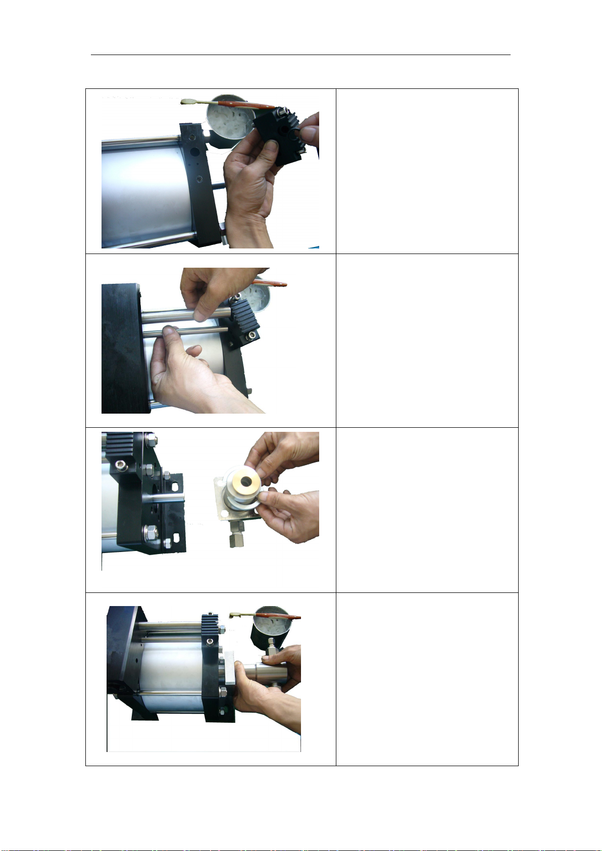
8.0 Driving body and high-pressure part
8.1 Disassembly steps
Removal of four screws for fixing
left and right high pressure
cylinders with M12 hexagonal
wrench(M12*25).
Slowly pull out the high pressure
cylinder to avoid accidental
injury to the piston rod.
The high-pressure seal in the
high-pressure cylinder can be
removed by tools. The sealing
seat can be taken out first, and
then the O-ring can be taken out.
The H605 high-pressure seal can
be taken out directly by tools to
clean the high-pressure cylinder.
The high pressure cylinder has:
high pressure seal and high
pressure guide sleeve.

High-pressure cylinder:
high-pressure seals and
high-pressure guide sleeve.。
Remove the pipes of 16 and 10.
Note that there are sealing rings at
both ends of the pipes.
(d6.9*1.8) 2 pieces
(d11.2*2.65) 2 pieces
A rubber hammer is used to strike
the edge of the end cap and
remove the end cap to separate it
from the driving cylinder.
When the seal in the end cap is
removed by the tool, the smooth
ring of the seal can be removed
first, and then the O-ring can be
removed. The UN seal can be
removed directly by the tool, and
the sealing groove can be cleaned
by non-corrosive solvent.

8.2 Installation steps
First, clean the parts and grease
the sealing parts.
High-pressure seals are
assembled in sequence.
High-pressure seals can be
installed with O-rings first, and
then into seats. H605
high-pressure seals can be
directly loaded.
Clean the shaft seal, apply grease,
assemble into the left and right
end caps. The O-ring and the
smooth ring can be separated by
the shaft package matching.
Firstly, the O-ring is loaded into
the sealing groove, and then the
smooth ring is loaded into the
groove. The 072 shaft seal can be
assembled in different directions,
and the UN shaft seal can be
directly loaded into the groove.
Assemble the pull rod of the
scaffold and place it on the marble
platform and lock the nut tightly.
When assembling the valve block,
the O-ring on the valve block
needs to be assembled first.
(d11.2*2.65) 1 pieces
(d6.9*1.8) 1 pieces
(d4.5*1.8) 2 pieces
Assemble the gas distribution
pipe and install the gas seal ring
before assembling.
(d11.2*2.65) 1 pieces
(d6.9*1.8) 1 pieces
Assemble the clasp jacket, first
put it into the clasp jacket, then
clamp the fixed groove of the high
pressure cylinder with the clasp.
When assembling the
high-pressure cylinder, when
tightening the screw of the
high-pressure cylinder, attention
should be paid to ensure that the
one-way valve at the inlet and
outlet of the high-pressure
cylinder is parallel to the scaffold,
and then tighten four pieces of
screw.

8.3 Check valve assembly
DGG10/16/28 Assembly Drawings
8.4 Attribute description of parts and components of one-way valve
NO
Name
figure number
quantity
1
o-ring
ORING-18*3.55
2
2
stainless steel ball
S¢20-001
2
3
Compression spring
D18.3*CS0.85*30-7
2
4
Support sleeve
DF 01017-001
2
5
o-ring
d30*1.8-90°
2
BPL 100 Assembly Drawing
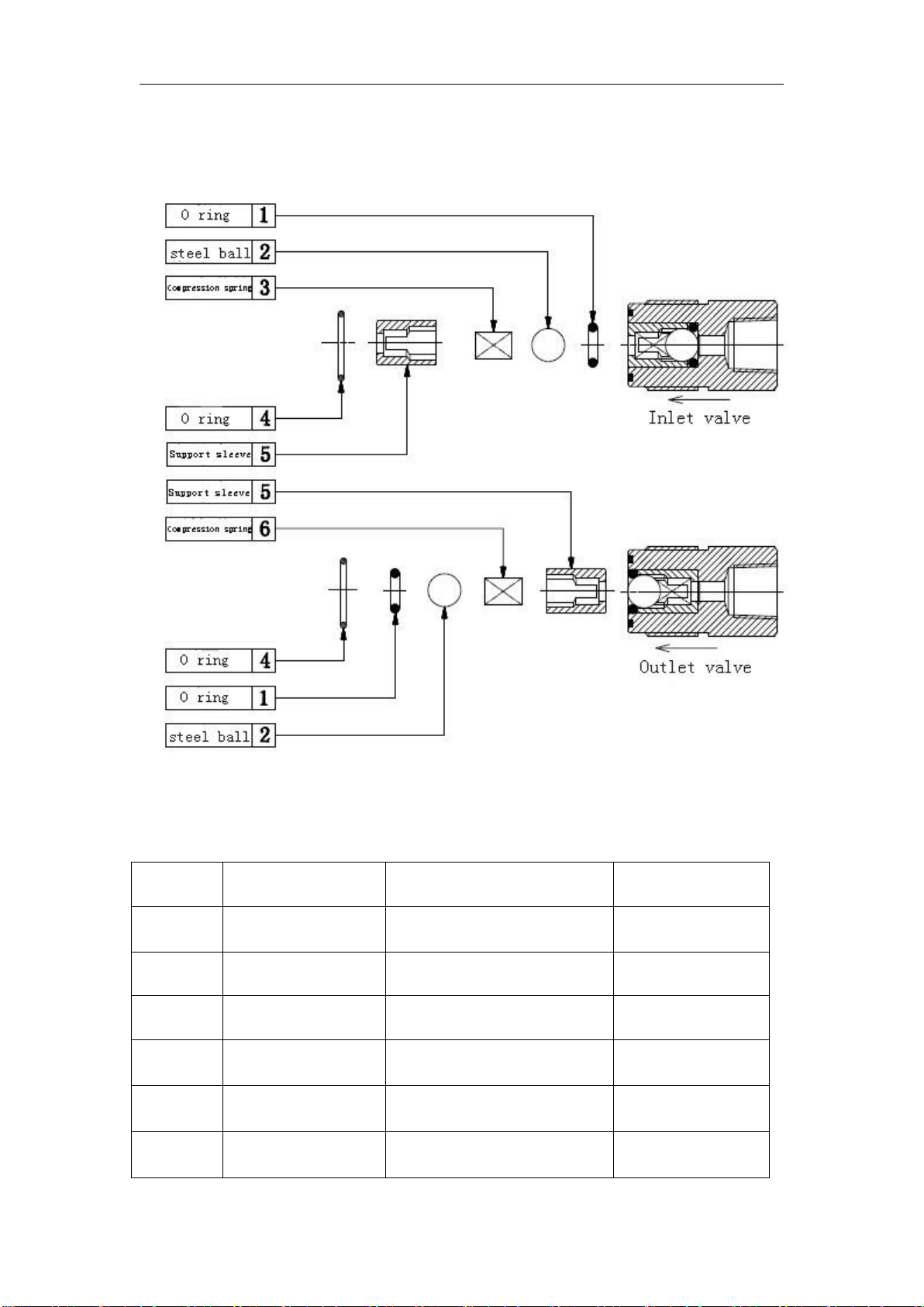
8.5 Check valve assembly
DGG40/64/80/100/130 Series One-way Valve Import and Export Drawing Assembly
8.6 Attribute description of parts and components of one-way valve
NO
Name
figure number
quantity
1
o-ring
ORING-8*2.65-90°
2
2
stainless steel ball
S¢10-001
2
3
Compression spring
D7.6*CS0.4*17-9
1
4
o-ring
ORING-18*1.8-90°
2
5
Support sleeve
DF03006-001
2
6
Compression spring
D8*CS0.5*17-9
1
BPL 100 Series one-way Valve Import & Export Drawing Assembly
8.6 Attribute description of parts & components of one-way valve

8.7 Check valve assembly
DGG175/255/400 Series One-way Valve Import and Export Assembly Drawings
8.8 Attribute description of parts and components of one-way valve
NO
Name
figure number
quantity
1
o-ring
ORING-5*2-90°
2
2
ceramic ball
S¢6-001
2
3
Compression spring
D3.95*CS0.45*10.5-9
2
4
spool
DC06027-002
2
5
o-ring
ORING-15*1.8-90°
2
BPL 100 Series one-way Valve import & export assembly drawings
8.8 Attribute description of parts & components of one-way valve

TRITORC INC-USA
5041 Spencer Highway Suite #302, Pasedena, Texas – 77502
Web: - www.tritorc.com
Table of contents
Other TRITORC Water Pump manuals

Popular Water Pump manuals by other brands

Z.I.P.P.ER MASCHINEN
Z.I.P.P.ER MASCHINEN ZI-GP1200 user manual

Jula
Jula 731-077 operating instructions

Kamoer
Kamoer F4 user manual

Speck pumpen
Speck pumpen BADU Block Series Installation & operating manual

Samoa
Samoa LARIUS GIOTTO operating instructions

MKS
MKS Granville-Phillips 835 VQM Series instruction manual


DAB
DAB FK Series Instruction for installation and maintenance

Knauer
Knauer Azura P 4.2S instructions

PYD Electrobombas
PYD Electrobombas PC 32 8 220 instruction manual

Wilden
Wilden PS Stallion Series manual

INOXPA
INOXPA HYGINOX SE-15 Installation, service and maintenance instructions

Ulvac
Ulvac G-20DA instruction manual