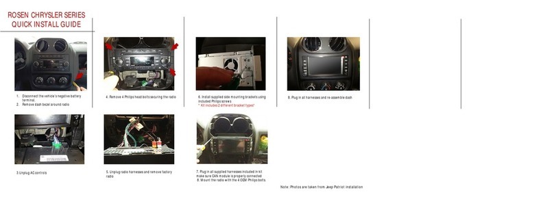
Trivisio Colibri User manual


Contents
1 Introduction 3
2 Installation 4
2.1 Windows ..................................... 4
2.2 Linux ...................................... 6
3 GUI 7
3.1 Starting the application ............................ 7
3.2 The GUI ..................................... 8
3.3 Calibration parameters ............................. 11
3.4 Boresighting ................................... 12
3.5 Jitter Reduction ................................. 13
3.6 Additional functionality ............................ 13
3.6.1 Disable drawing of textures ...................... 13
3.6.2 Additional COM ports to scan ..................... 14
3.6.3 Sensor Diagnosis ............................ 15
3.6.4 Firmware Upgrade ........................... 16
4 SDK 18
4.1 The test.c example .............................. 18
4.2 The orientation.cpp example ........................ 21
4.3 Simple Import mechanism for data profiling ................. 21
Colibri User Manualsdf df 1


Chapter 1
Introduction
Thank you for purchasing the Trivisio Colibri and using its software development kit
(SDK).
This user’s manual covers the software available for the Colibri Tracker. Chapter 2is
an installation guide for the software. The graphical user interface (GUI) provided with
the sensor is described in Chapter 3. It covers the functionality of the GUI and does also
gives some hint on how to get the most out of the Colibri Tracker. Chapter 4describes
two examples of using the SDK’s API. The code of one of the examples is studied in
detail.
Colibri User Manualsdf df 3

Chapter 2
Installation
This chapter provides the installation guides for Microsoft Windows and Linux.
If you do not have an installer yet, please download the installation file from the
Trivisio GmbH website: http://www.trivisio.com. Installers for Window and Linux
(32 and 64 bit) can be freely downloaded from the Support — Software section (http:
//www.trivisio.com/index.php/support/software).
Download the installer for your system, and continue to the section covering the in-
stallation guidelines for your operating system.
2.1 Windows
Run the installer, the following images will then guide you through the installation pro-
cedure.
Step 1: Welcome Screen
This is the welcome screen of the installer. Press next to start the installation or cancel
to abort.
4 Colibri User Manualsdf df

Step 2: EULA
The next dialog is the End User License Agreement. Please read it carefully.
If you agree to the terms and conditions, please press the “I Agree” button to continue
the installation procedure.
Step 3: Installation path
In this dialog the user is able to choose or select the desired installation path.
Colibri User Manualsdf df 5

Step 4: Start menu folder
If you want to have a different name for your start menu folder, please modify the path
to your personal need.
Step 5: Component installation
The next dialog can be used to select different installation types. The default installation
type is FULL.
The different options are: Full, Developer, GUI, and Custom. The Full installation
comprise the Developer and GUI installations.
After this dialog the installation is executed and you are able to use the applications
and develop your own software based on the SDK.
2.2 Linux
Simply run the installer, accept the EULA, and follow the instruction presented.
6 Colibri User Manualsdf df

Chapter 3
GUI
This section provides an overview about the graphical user interface, which can be used
to view the connected sensors and their values.
3.1 Starting the application
Using Microsoft Windows
You can start the application either by clicking the Trivisio – Colibri icon on your
desktop or by selecting it from the start menu. The default location is: Trivisio –
Colibri X.X.X (see below) and execute the Trivisio – Colibri.
Using Linux
Execute the TrivisioGUI executable, available in the bin directory of the installation.
Colibri User Manualsdf df 7

3.2 The GUI
This is a snapshot of the GUI application.
Based on this image, the functionality will be described briefly below:
1. The list of Colibri sensors found connected to the system.
Detailed information about each sensor can be viewed and changed by expanding the
tree view by pressing the “plus” symbol. There might be sensors marked with red.
These are equipped with an outdated firmware version, which must be updated
before the sensor can be accessed or used. See Section 3.6.4. The sensors are
identified by their serial number and firmware version.
When a sensor is not running, it is possible to change its settings. The boresighting
setting, further described in Section 3.4, is an exception to this rule as it can also
be changed when the sensor is running.
By expanding the Sensor Config (see figure below), it is possible to see what indi-
vidual sensor elements are enabled in the Colibri. The user can enable the individual
magnetometers,accelerometers, and gyroscopes, and also the built in temperature
sensor. The Orientation sensor turns on the Colibri’s virtual orientation sensor.
When using the orientation sensor, all accelerometers, gyroscopes and magnetome-
ters will automatically be turned on and cannot be deactivated before the orientation
is deactivated.
The Magnetic div determines the sensitivity of the magnetometers. A higher value
improves the magnetic measurements, but does also take more time to measure.
8 Colibri User Manualsdf df

RAW ASCII Enabled displays
off off Sensor and graphs
on off Only graphs
off on No output
on on No output
Sensors that can be enable.
Hence, if you experience problems with too low update rate, try reducing the mag-
netic divisor. A value of 256 is suitable to maintain 100 Hz sampling frequency.
The frequency at which the Colibri delivers data is determined by the External
trigger setting, which indicates if the IMU is triggered from an external source or
by the Frequency setting. Not all Colibri’s are delivered with the possibility to be
Some Colibri’s also come with the ability to emit a trigger signal (again contact
sor determines how often a trigger signal should be emitted. If set to 0 no trigger
signal is output, and otherwise the output frequency is the sensor frequency divided
by the divisor.
In addition, the option ASCII turns on output suitable for terminal debugging
can be activated, the AutoStart determines if the sensor starts automatically to
output measurements when plugged in, and the RAW mode can be used to get raw
uncalibrated data from the IMU.
Turning on Jitter reduction gives a more stable orientation estimate, as explained
in Section 3.5.
Note: the available graphical output depends on the settings of ASCII and RAW.
The modes and the according enabled widgets are shown in the following table.
2. Start/stop button.
The currently selected Colibri can be started and stopped using this button.
3. Rescan button.
Use the rescan button to search the system for connected sensors.
4. Save configuration button.
Normally, the selected sensor configuration is downloaded (but not saved to the
Colibri) as it is started and will be reset once the power is lost. Use this button to
save the configuration to the Colibri’s permanent memory.
Colibri User Manualsdf df 9

5. Euler angle orientation.
This describes the rotation of the Colibri as a sequence of three rotations, yaw
(around the sensors positive z-axis), pitch (around the sensors negative y-axis), and
finally roll (around the positive x-axis). Note that boresighting changes the sensors
axis.
6. OpenGL R
representation of the sensor orientation.
The OpenGL R
textures can be enabled or disabled by the menubar item Config-
uration.
7. Graph of the magnetometer measurements
8. Graph of the accelerometer measurements.
9. Graph of the gyroscope measurements.
10 Colibri User Manualsdf df

3.3 Calibration parameters
To view the calibration parameters used to calibrate the IMU, use the Calibration
Parameters menu item in the Device menu. The dialog looks as follows:
The Colibri sensors are factory calibrated and tested before being shipped. However,
the magnetic calibration is very sensitive to the environment in which the sensor is used.
This means that to obtain best possible orientation estimates, the Colibri should have
its magnetometers recalibrated after it has been mounted in the way it is intended to be
used. Not doing so will result in degraded orientation estimates.
To recalibrate the magnetometers, press the Run Calibration button in the view for
the magnetometer calibration parameters. Then turn the sensor around all its axis in a
smooth motions. If the calibration is successful, the parameters are downloaded to the
IMU, and if not the calibration is simply left unchanged.
Colibri User Manualsdf df 11

3.4 Boresighting
Boresighting can enabled and disabled in the tree view of the sensor (see 1in the image
below). When turned on this way, the Colibri will be boresighted according to the pa-
rameters saved in the sensor. The menu items in the Configuration→Boresight menu
allows the user to update these parameters (see 2in the figure below). Three different
types of boresighting are possible:
•Heading reset, global frame is aligned with the current sensor x-axis (set yaw = 0).
The vertical direction remains unchanged.
•Object reset, which changes the sensor coordinate system to align its z-axis with
gravity. The heading is unchanged.
•Alignment reset, which combines heading and object reset.
12 Colibri User Manualsdf df

3.5 Jitter Reduction
In settings where it is more important to have a smooth orientation estimate than high
precision (especially when the Colibri is nearly stationary) jitter reduction should be
turned on. This can be done with the checkbox in the expanded tree view of the sensor.
If you check it, jitter reduction is enabled otherwise not.
3.6 Additional functionality
3.6.1 Disable drawing of textures
The menu bar contains the Configuration menu entry (see image above). If the graphics
card is not powerful enough to render the textures, the textures can be switched off to
improve the performance.
Colibri User Manualsdf df 13

3.6.2 Additional COM ports to scan
The Trivisio GUI does its best to find all available sensors, but it sometimes fails due
to system specifics. One such reason is having a sensor connected via RS232. In this
cases it is possible to manually specify additional COM ports or devices to be scanned for
Colibris. To do so, select the Additional COM ports to scan from the Device menu.
It is then possible to enter additional COM ports and devices in the dialog that opens up
(see below). Note: In order to scan for the new ports and have the devices in the list,
you must press the Rescan button!
14 Colibri User Manualsdf df

3.6.3 Sensor Diagnosis
The GUI comes with the possibility to derive diagnostic sensor information to simplify
fault analysis. The diagnostic information contains information about all settings stored
in the Colibri, as well as the result from a few seconds of collected data. This provides
valuable information about the IMU such as bias and noise levels in the current setting.
Please, always provide this information with support requests.
To obtain the diagnostic information, select Run Diagnosis from the Device menu
and keep the sensor as stationary as possible. The best information is obtained if the
sensor is diagnosed in the same environment as it is used.
The result dialog can be seen below. It is possible to save the output to a text file
which can easily be attach to support requests.
Colibri User Manualsdf df 15

3.6.4 Firmware Upgrade
If your sensor is marked as red in the device list, the firmware of the sensor must be
upgraded.
To upgrade the firmware, select the sensor in the list and select Upgrade Firmware
from the Device menu. You are next asked, if you are sure to upgrade your firmware:
By pressing OK a new dialog will open with instructions on how to upgrade the
firmware. Please follow the instructions.
16 Colibri User Manualsdf df

Within 10 seconds after initiating the firmware upgrade procedure a new USB mass
storage device named ’FIRMWARE’ should become available on your computer. Once
the unit appears:
1. Copy the firmware file (e.g., colibri1500.fmw) to this drive. The installer comes with
a firmware version that should be compatible with the SDK version. It can be found
in the firmware folder of the installed program. The latest firmware can also be
2. When receiving a new firmware file the USB mass storage should safely remove
itself. If this does not happen, for example due to aggressive caching, safely remove
it manually to speed up the procedure.
3. Unplug and then replug the sensor to complete the firmware update. Check the
sensor entry in the GUI to see that the upgrade was successful.
Colibri User Manualsdf df 17

Chapter 4
SDK
Two example programs are provided with the SDK. The first one is a console application
named ColibriTestC (testc.c) and the second one is a GLUT R
application. The
Windows SDK also comes with an example on how to communicate with the sensor using
C#.
The two applications can be found in the installation directory in the example di-
rectory. The Windows installation contains Visual Studio project for the two examples
and a solution in the installation directory. The Linux installation includes the makefile
Makefile.linux.
The required header files are in your installation directory in the include folder. The
libraries are found in the lib or bin directory.
4.1 The test.c example
This section describes the test.c application.
The TrivisioColibri.h header is needed to use the Colibri API.
1#include "TrivisioColibri .h"
2
3#include <s t d i o . h>
4#i f d e f WIN32
5# include <windows . h>
6#e l s e
7# include <u n i s t d . h>
8#e ndif
9
10 #define M_PI 3.14159265358979323846
This simple example contains just a main function. In it the Colibri sensors are scanned
and the measurements are printed to the console. In addition the methods for getting
and setting the configuration will be shown.
12 int main ( )
13 {
14 struct T r i v i s i o S e n s o r s e n s o r L i s t [ 1 0 ] ;
15 int sensorCount = c o l i b r i G e t D e v i c e L i s t ( s e ns o r L is t , 1 0 ) ;
The available devices can be detected by calling the colibriGetDeviceList function.
The function returns the number of available sensors, and it takes two parameters; an
array of sensors to be populated and the size of this array.
18 Colibri User Manualsdf df
Table of contents
Other Trivisio GPS manuals
Popular GPS manuals by other brands
Garmin
Garmin nuvi 1690 Safety and product information
Flybox
Flybox Omnia57 Series Installation and User Manual, Safety Instructions and Warning Booklet
Teltonika
Teltonika FMB920 user manual

Neoway
Neoway Neo_M660A Hardware user's guide
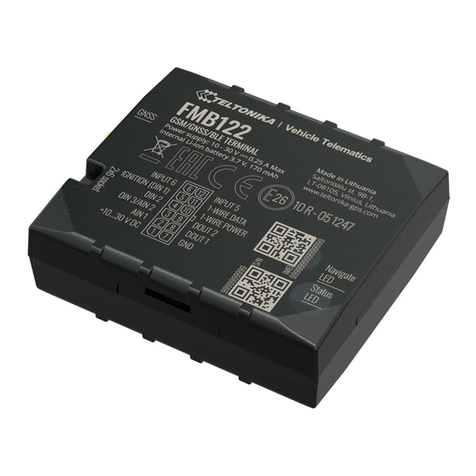
Teltonika
Teltonika FMB122 Quick manual

Magellan
Magellan RoadMate 760 - Automotive GPS Receiver manual


