Flybox Omnia57 Series Product manual
Omnia57 VOLT-AMP - Installation and User Manual,
Safety Instructions and Warning Booklet
FLYBOX
Rev. 1.0
®
1
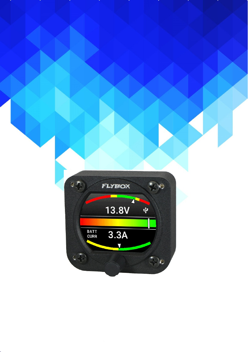
VOLT-AMP
(Omnia57 family)
Flybox
®

Installation and User Manual, Safety
Instructions and Warning Booklet
This product is not TSO’d and cannot be installed into
traditional FAA Part 23 and similarly Type-Certificate Aircraft
Document A2019VOLT-AMP
Revision#1.0, 02/2019
For firmware version 1.0

MECHANICAL INSTALLATION
SECTIONS
ELECTRICAL INSTALLATION
OPERATING INSTRUCTIONS
INSTRUMENT SETTINGS
INTRODUCTION
IMPORTANT NOTICE AND WARNINGS
INDEX
OMNIA57 FAMILY SYSTEM OVERVIEW
TECHNICAL SPECIFICATIONS
WARRANTY
DISCLAIMER
Examples of different configurations

FLYBOX
Omnia57 VOLT-AMP - Installation and User Manual,
Safety Instructions and Warning Booklet
Rev. 1.0
®
Introduction
Thank you for purchasing a Flybox® Omnia57
instrument.
Our intent in developing the Omnia57 instrument family
was to create a light and compact product, powerful and
easy to install and use.
The Omnia57 instrument family is equipped with a
state-of-the-art highly visible display, a powerful 32 bit
microcontroller and the latest generation of solid state
sensors to ensure reliability and accuracy over time.
The owner has the possibility to keep the instrument
software up-to-date by downloading the latest available
revision from the www.flyboxavionics.it website and
installing it using a USB pen drive.
We are confident our products will be satisfactory and
will make your flying experience a pleasant one.

Omnia57 VOLT-AMP - Installation and User Manual,
Safety Instructions and Warning Booklet
FLYBOX
Rev. 1.0
®
Important notices & warnings
Symbols used in the Installation and User Manual,
Safety Instructions and Warning Booklet
NOTE: Used to highlight important information.
CAUTION: Used to warn the user, it indicates a
potentially hazardous situation or improper use of the
product.
WARNING: Used to indicate a dangerous situation that
can cause personal injury or death if the instruction is
disregarded.

FLYBOX
Omnia57 VOLT-AMP - Installation and User Manual,
Safety Instructions and Warning Booklet
Rev. 1.0
®
Important notices & warnings
WARNING: It is the owner’s responsibility to test this device
before operating the aircraft and to make sure nobody is
using it unless properly instructed and authorized to do so.
WARNING: This device is intended to be installed on
NON-TYPE CERTIFIED AIRCRAFT ONLY, as it does NOT
require any air operator’s certificate. Refer to your national
aviation authorities to check if this device can be installed on
your aircraft.
WARNING: These instructions must be provided to users
before use, and retained for ready reference by the user.
The user must read, understand (or have explained) and
heed all instructions and warnings supplied with this product
and with those products intended for use in association with
it. Always keep a copy of the Installation and User Manual,
Safety Instructions and Warning Booklet on the aircraft. In
case of change of ownership, the Installation and User
Manual, Safety Instructions and Warning Booklet must be
delivered together with all of the other papers.
WARNING: Read the Installation and User Manual, Safety
Instructions and Warning Booklet before installing the device
on your aircraft and follow the procedure described therein.
WARNING: Once the installation process is completed, it is
extremely important to test the device before taking off to
make sure it works properly. Therefore, we strongly suggest
to double check all of the electronic instruments available on
the aircraft and to turn them on to verify they function correctly.

Omnia57 VOLT-AMP - Installation and User Manual,
Safety Instructions and Warning Booklet
FLYBOX
Rev. 1.0
®
Important notices & warnings
WARNING: Alterations, additions, or repairs not performed
by the instrument manufacturer or by a person or organization
authorized by the manufacturer shall negate any warranty.
WARNING: It is the responsibility of the installer to properly
install the device on the aircraft. In case of calibration, or any
technical or functional customization of the device, the
responsibility lies with the individual who carried out such
operation.
FAILURE TO DO SO MAY RESULT IN SERIOUS INJURY
OR DEATH.
WARNING: This device is operated through a software which
from time to time can be updated and/or subject to change.
Please, always refer to the Installation and User Manual,
Safety Instructions and Warning Booklet for the last updated
version of the software available at www.flyboxavionics.it
WARNING: Do NOT rely on the Omnia57 Fuel L-P device
ONLY to determine the level of the fuel available in the tanks.
WARNING: If this product is not used correctly, or it is
subjected to additions or alterations, the effectiveness
of this device may be considerably reduced.
WARNING: The unit isn’t waterproof. Serious damage could
occur if the unit is exposed to water or spray jets.

FLYBOX
Omnia57 VOLT-AMP - Installation and User Manual,
Safety Instructions and Warning Booklet
Rev. 1.0
®
Important notices & warnings
NOTE: The Installation and User Manual, Safety Instructions
and Warning Booklet will be updated annually if needed.
All changes or updates will be published on our website
www.flyboxavionics.com in the "support" section.
NOTE: Upon receipt of the instrument it is advisable to register
on our website www.flyboxavionics.it in the "product
registration" section.
The Registration data will be used only to send important news
or information about available firmware updates or to
communicate safety information about the instrument.
NOTE: Flybox Avionics reserves the right to change or
improve its products as well as terms, conditions, and notices
under which their products are offered without prior notice.
NOTE: The consumer decides of his own free will if the
purchased product is suitable and safe for his need. If the
consumer does not agree with the notices contained in this
Installation and user Manual, Safety Instructions and Warning
Booklet, do not install this instrument in his aircraft.

Omnia57 VOLT-AMP - Installation and User Manual,
Safety Instructions and Warning Booklet
FLYBOX
Rev. 1.0
®
i
Index
INDEX
SECTION 1 - Omnia57 Family System overview..………… 1
1.1 - Construction Features …….…………………………..…. 1
1.2 - Ergonomics………...…...………….……………………. 1
1.3 - Interconnection Ability ………...…...…………..……….. 2
1.4 - Easy Software Update ………...…...………….…………. 3
1.5 - Easy Datalog Saving ………...…...………….…………… 3
1.6 - Interfaces ……..…...…...………….……………………… 4
SECTION 2 - Mechanical installation….……………………… 5
2.1 - Mechanical Dimensions……………..….………………… 5
2.2 - Sensors Installation…………..………..………………….. 7
SECTION 3 - Electrical Installation.…...…….….….….……… 8
3.1 - Rear Panel Connections…………..…….….………..…… 8
3.2 - 22 Pole Female Connector Wiring……………………… 9
3.3 - 22 Pole Connector Table……………………………….… 10
3.4 - Curent Sensors Connections…….…..…..…..….….…… 11
3.5 - CAN bus Connection Wiring.………….………………… 14
3.6 - CAN Bus Connector Tables……………………………… 15
SECTION 4 - Instrument settings……….………….…………. 16
4.1 - Minimum Settings Before First Use.…..….….…….…… 16
4.2 - Panel Indicators And Commands…..…….………….…. 17
4.3 - Setup Menu Navigation……….…….…..…….………… 18
4.4 - Main Setup Menu… ………………………….………… 19
4.4.1 - Gauges Submenu…….. …………………….………… 21

FLYBOX
Omnia57 VOLT-AMP - Installation and User Manual,
Safety Instructions and Warning Booklet
Rev. 1.0
®
ii
Index
4.4.2 - Volt Submenu……..…………………….………… …… 22
4.4.3 - Ampere Submenu………….……….…………………… 26
4.4.4 - Indicator Mode………..…………………………………. 29
4.4.5 - Diagnostic Mode…….….…….……….…………….…… 30
4.6 - Offset 1 Calibration..………….…………………………… 33
4.7 - Offset 2 Calibration .………………………………………. 35
4.8 - Backlight Submenu.….….…….…….…….……….……… 37
SECTION 5 - Operating Instructions……….…………………… 40
5.1 - Firmware Upgrade..……………..…..….….…….………. 40
5.2 - Backup/Restore……………….…..…….………….….…. 43
5.3 - Use Of The Instrument……….…….…..…….……………. 45
5.4 - Logger…..………. ………………………….……………. 48
TECHNICAL SPECIFICATIONS…………………………… 49
CLEANING…………………………………………………….. 49
WARRANTY……………………………………………….…… 50
TERM OF USE AND DISCLAIMER…………………….…… 51

Omnia57 VOLT-AMP - Installation and User Manual,
Safety Instructions and Warning Booklet
FLYBOX
Rev. 1.0
®
1
Omnia57 Family System Overview
The Omnia57 instrument family has many innovative
features, common to all models as described below.
OMNIA57 FAMILY SYSTEM OVERVIEW
1.1 CONSTRUCTION FEATURES
Omnia57 instrument family is built from solid aluminum
alloy, CNC milled and powder coated to last a long time
over the years always showing a new appearance.
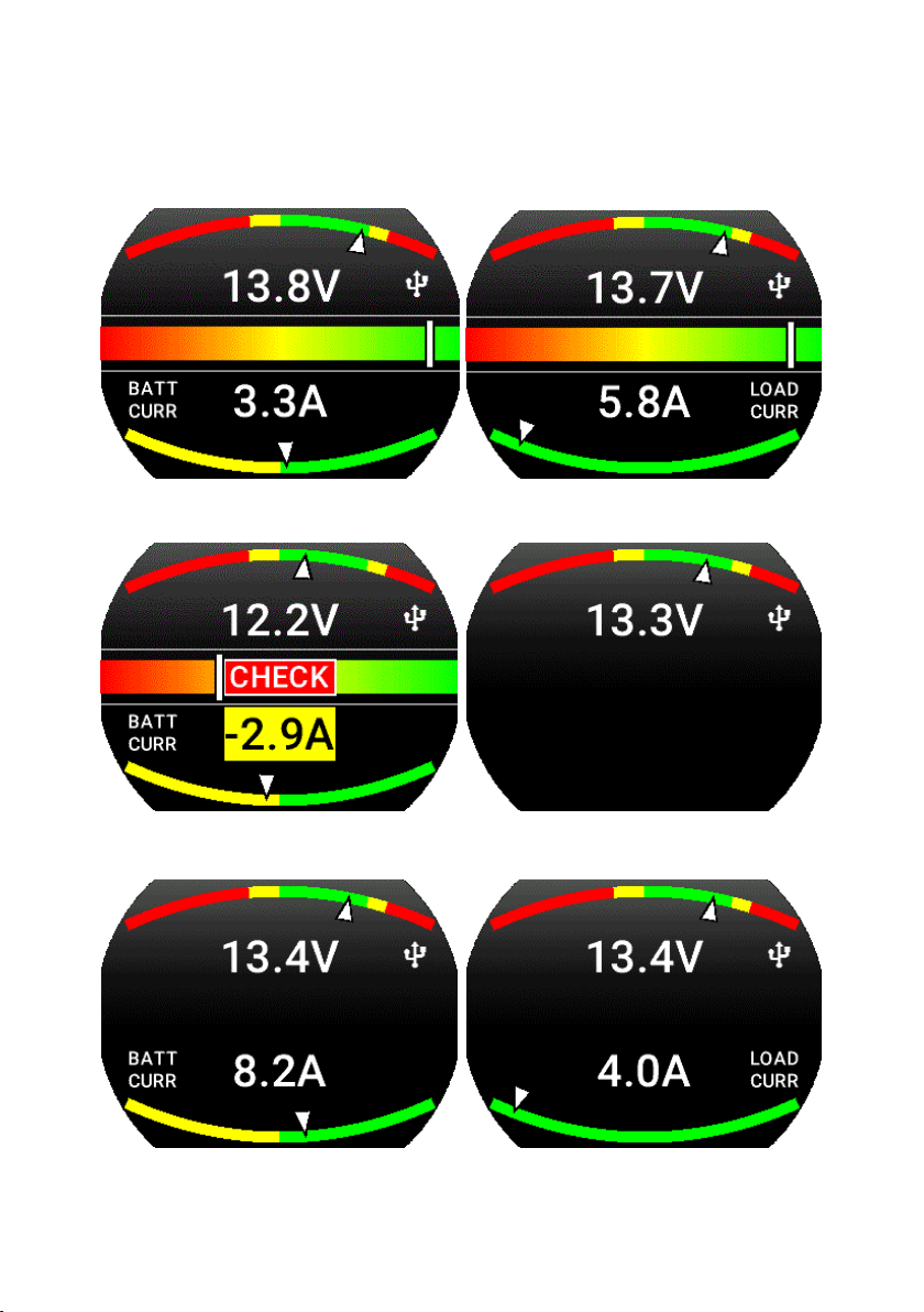
- Large 2.4 inch TFT display, 320x240 Pixels, 1000 nits,
antiglare surface, sunlight readable, wide temperature
range.
- A high quality knob encoder with push button for easy
access to all features.
- Backlight auto dimming feature with one optional sensor
for all the Omnia57 installed in the panel.
1.2 ERGONOMICS
FLYBOX
Omnia57 VOLT-AMP - Installation and User Manual,
Safety Instructions and Warning Booklet
Rev. 1.0
®
2
Omnia57 Family System Overview
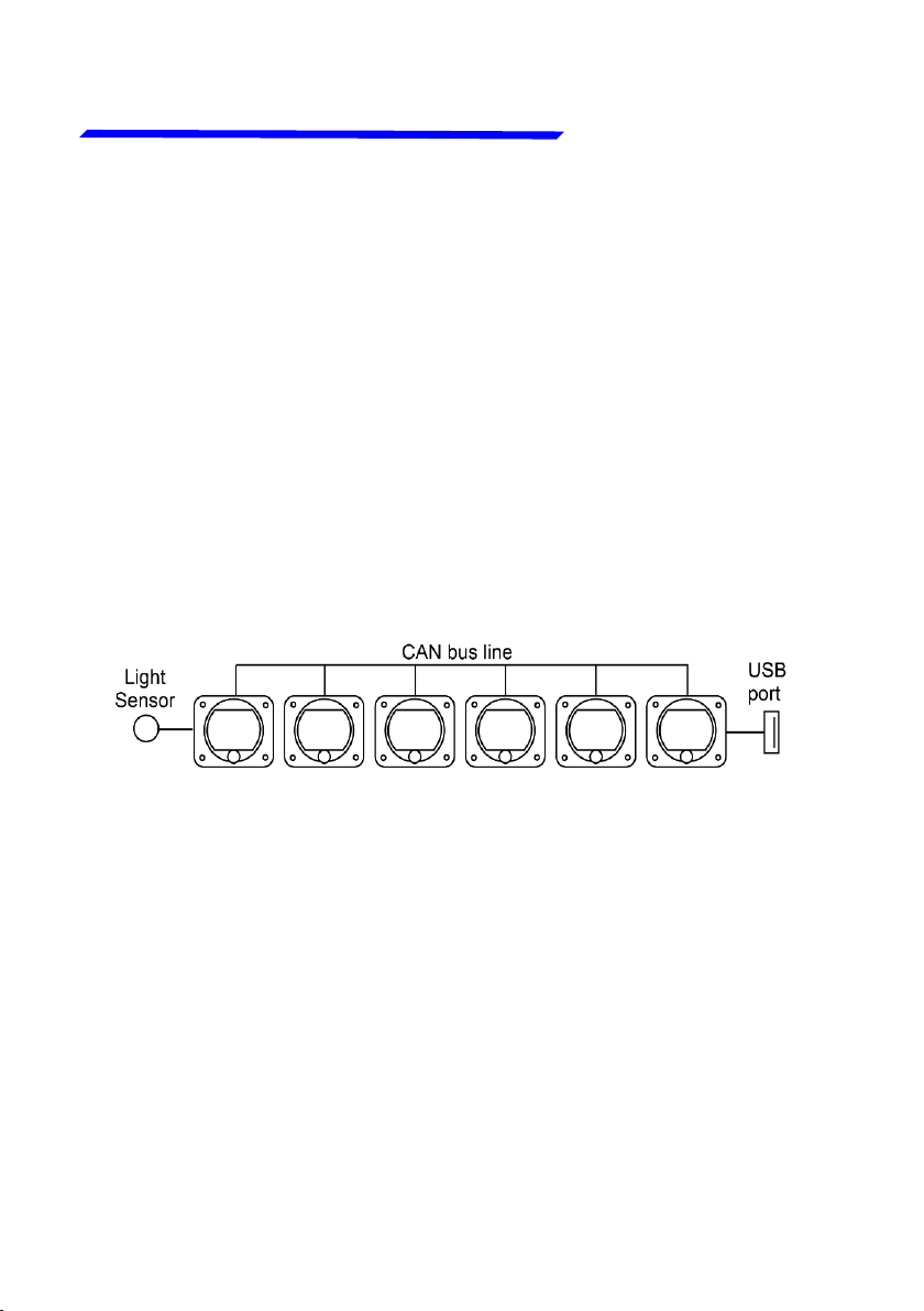
1.3 INTERCONNECTION ABILITY
All the instruments of the Omnia57 family can be
connected together to form a communication network,
making some data exchange operations simpler.
The software update of a Omnia57 instrument connected
in group takes place through the CAN bus communication
with the instrument that has the USB pen drive connected.
This means that the USB connection is made to a single
instrument, and the information will be forwarded via CAN
bus to or from all the others in the group.
The configuration data and the data logger of the
interconnected instruments are saved or restored via CAN
bus on the same USB pen drive. A single brightness sensor
can provide information to all the connected instruments
to automatically adjust the backlight intensity.
Up to 16 Omnia57 can be connected together through
the CAN 1 bus.

Omnia57 VOLT-AMP - Installation and User Manual,
Safety Instructions and Warning Booklet
FLYBOX
Rev. 1.0
®
3
Omnia57 Family System Overview
1.4 EASY SOFTWARE UPDATE
The user can download any new firmware, when available,
from Flybox website, connect a USB pen drive to the
instrument and freely update it with the last features.
With one USB connection only, it will be possible to update
every instrument installed in the panel. If more Omnia57
are installed and properly connected, they will search for
the right firmware through the CAN bus.
1.5 EASY DATALOG SAVING
Easy logging of the data for debug purpose. If needed,
each Omnia57 unit can save a last flight log on the USB
pen drive. The user can then send the log via e-mail to
Flybox support for a help/support request.

FLYBOX
Omnia57 VOLT-AMP - Installation and User Manual,
Safety Instructions and Warning Booklet
Rev. 1.0
®
4
Omnia57 Family System Overview
All the Omnia57 instruments have the following common
interfaces:
2 separate CAN BUS: they can be used to connect the
Omnia57 instruments together, to interface them with
other Flybox instruments or with external devices like
Engines ECUs or new devices that will be possibly
developed in the future.
2 RS232 serial ports: used to connect the Omnia57
instruments to an external GPS (when applicable). This
feature appears in some models only.
1 Sensor Light Input: if connected, it allows the automatic
light intensity adjustment, one sensor for all the
instruments.
2 Power outputs for sensors: one 12 V 500mA@60°C
and the other 5 V 350 mA@60°C, both protected from
short circuit.
1 Alarm output: all the Omnia57 instruments can activate
an external warning device like a lamp or a small relay
through this NPN transistor output.
1.6 INTERFACES
Caution!
High current PIN 2
If the current on one of the
outputs is too high, a caution
message will appear.

Omnia57 VOLT-AMP - Installation and User Manual,
Safety Instructions and Warning Booklet
FLYBOX
Rev. 1.0
®
5
Mechanical installation
MECHANICAL INSTALLATION
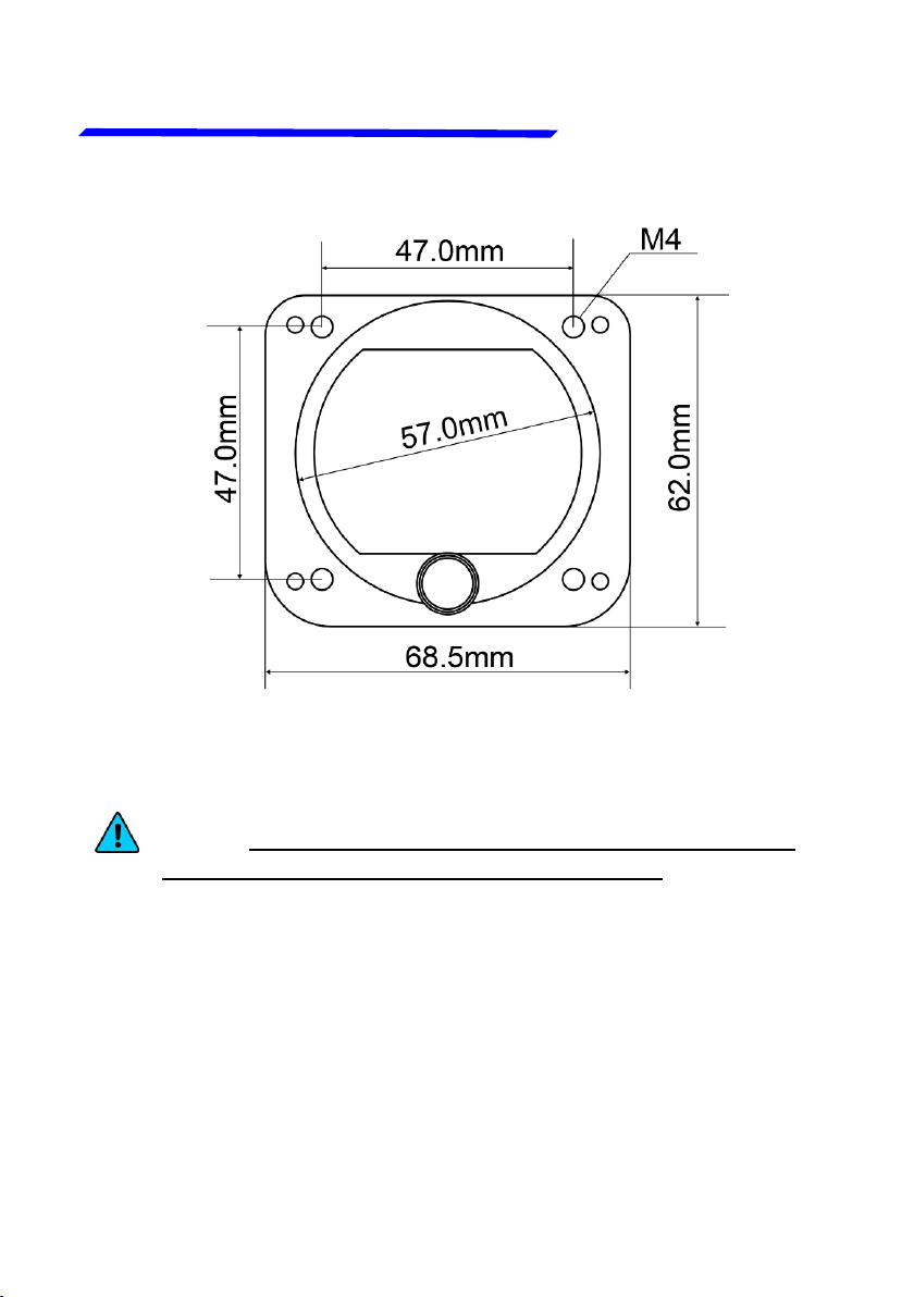
The Omnia57 Fuel VOLT-AMP instrument fits in a
standard 2 ¼” (57 mm) panel cutout; it's recommended to
choose a position that permits optimal display visibility. It's
furnished with four M4 screws to install it to the panel, if
you use other screws consider that the maximum thread
length inside the instrument body is 10mm (see the picture
below).
2.1 MECHANICAL DIMENSIONS
FLYBOX
Omnia57 VOLT-AMP - Installation and User Manual,
Safety Instructions and Warning Booklet
Rev. 1.0
®
6
Mechanical installation
NOTE: For an installation without interference, consider
making a hole of at least 57.5 mm diameter

Omnia57 VOLT-AMP - Installation and User Manual,
Safety Instructions and Warning Booklet
FLYBOX
Rev. 1.0
®
7
Mechanical installation
Omnia57 VOLT-AMP has 3 analog inputs. One is for a
Voltage source and two can read one or two Flybox current
sensors code 601060 and 601061.
The voltage input can be connected to the +V bus behind
the instrument panel or directly to the battery. Connection
through 1 A fuse is recommended.
The Flybox current sensors are supplied bare and must
be installed insulating them from other metallic parts and
protected from moisture.
Usually they are installed behind the instrument panel or
in the engine compartment and covered by a simple plastic
sheet or cover.
Another way to insulate them is using a piece of shrinking
tube.
2.2 SENSORS INSTALLATION

FLYBOX
Omnia57 VOLT-AMP - Installation and User Manual,
Safety Instructions and Warning Booklet
Rev. 1.0
®
8
Electrical installation
3.1 REAR PANEL CONNECTIONS
2 x 2 - p o l e
connectors,
Molex Micro-
Fit for CAN 1
bus
22 pole female
connector, Molex
Micro-Fit. See the
table chapter 3.3
The required connectors and terminals are supplied with
the instrument.
The manufacturer’s codes are:
Molex P/N 43025-0200 (2 pole housing)
Molex P/N 43025-2200 (22 pole housing)
Molex P/N 43030-0007 (female crimp terminal)
The terminals can be crimped with:
- Flybox Professional Crimping Tool cod. 603000
- Molex tool P/N 63819-0000
Upper
Lower
ELECTRICAL INSTALLATION
2 x 2 - p o l e
connectors,
Molex Micro-
Fit for CAN 2
bus
USB 2.0 port
Upper
Lower
Omnia57 VOLT-AMP - Installation and User Manual,
Safety Instructions and Warning Booklet
FLYBOX
Rev. 1.0
®
9
Electrical installation
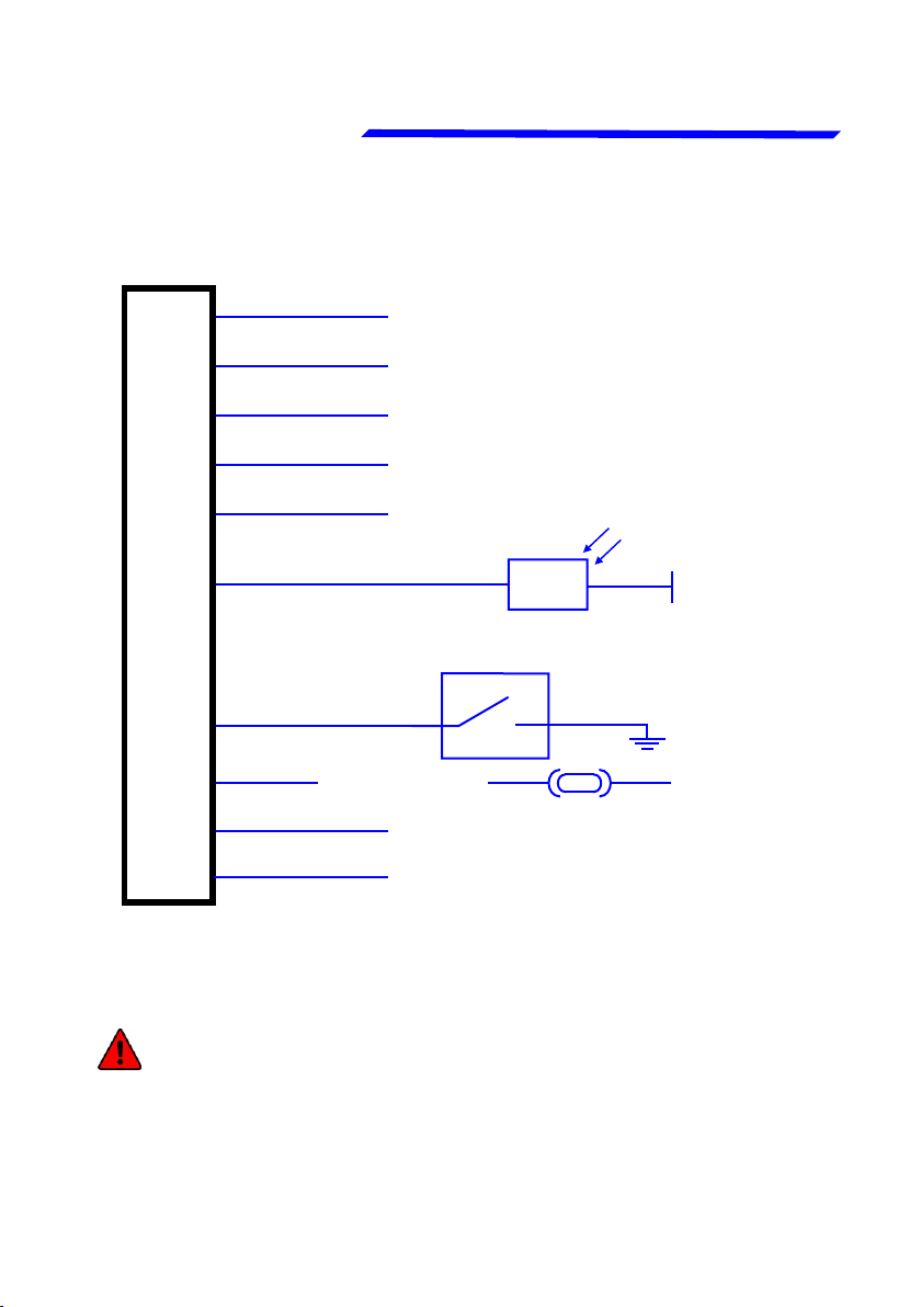
3.2 - (22 POLE) FEMALE CONNECTOR WIRING
WARNING: Voltage peaks on the supply line exceeding
the operating limits can damage the device.
+ V Main Supply
GND Main Supply
+ Vout for sensors
Alarm OUT
+ 5V OUT
Ambient light sensor + 5V OUT
External switch
Voltmeter Input
Ammeter 1 Input
PIN 1
PIN 12
SPST switch, its use will be
implemented in future updates
Flybox ambient light sensor
code:105800 (sold separately)
Light
sensor
PIN 2
PIN 13
PIN 3
PIN 14
PIN 5
PIN 15
PIN 16
PIN 17 Ammeter 2 Input
(connect to +V bus
or to the battery)
1A
Blue Green
Other manuals for Omnia57 Series
2
This manual suits for next models
1
Table of contents


