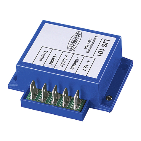
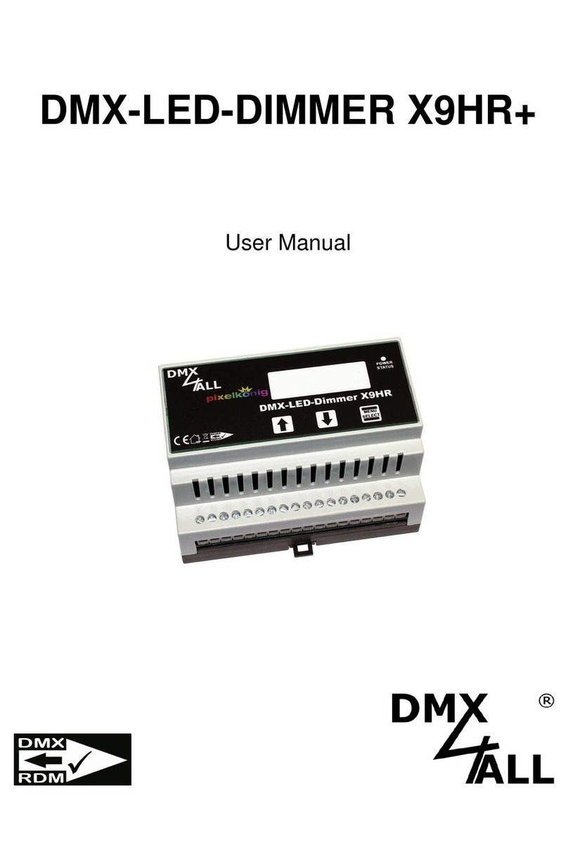
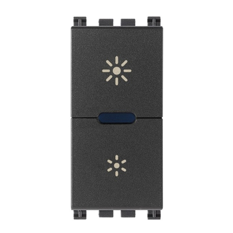
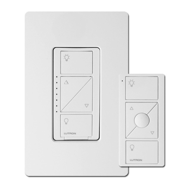
Tronico KUJU IMZ121H Operational manual

PRODUCT DATA SHEET
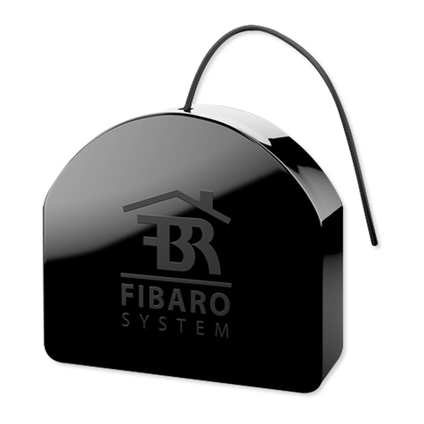
IMZ121H - Lighting Module Dimmer
Description
Insert module dimmer is designed to operate
without neutral wire. It operates with different
loads, including Incandescent lamps, halogen
lamps, dimmable LED, other dimmable loadings.
This device is compatible with standard Z-Wave
gateway or devices for remote control
Technical Specification
RF Frequency 919.80 MHz (HK), 868.40 MHz (EU/CN)
Transmission Range Up to 40 m Indoor
Loading Type Incandescent lamp ; Halogen lamp ; dimmable LED ;
other dimmable loadings
Loading Table Incandescent Lamp : 25W (Min. Load) / 300W (Max. Load)
Halogen lamp : 20W(Min. Load) / 240W(Max. Load)
Dimmable LED : 12W(Min. Load) / 120W(Max. Load)
Other dimmable loadings : 20W(Min. Load) / 240W(Max. Load)
Input Power AC 230V ; 50Hz
Number of Cables 2 wires (RED = LIVE; WHITE = LOAD)
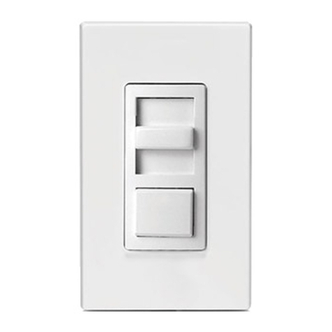
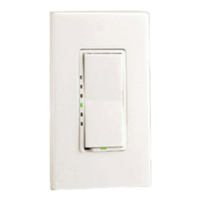
Support Local Panel Yes, both rocker switch or momentary switch
Indicator Green LED
Width 48 mm
Height 46 mm
Depth 18 mm
Weight 35 g
Accessory 2-wire connector & 4 wire connector (For local panel)
Operation Temperature 0 ~ 40 ℃
Relative Humidity 5 ~ 95 %
Standards EN 61058
Environmental Characteristic IP20 indoor use only
Telephone: (852)3907-9216 Email: [email protected].hk http://www.tronico.com.hk/
Supports any
lighting
switches
Supports any
dimmable light
sources
Dim your lights to create mood and ambience
Invisible

KUJU Technology Company Ltd.
Offi ce: No.1, Longh e Industr ial Zon e,Yangt ian Roa d,
Long gang Town ,Long gang Dist rict, Shenzhe n
Tel:86 (755)89 90-55 11 Fax:86(7 55)89 90-5733
E-ma il:kuju@t ronic o.com.h k
Tronico Technology Company Ltd.
Offi ce: Unit213 ,ICDeve lopmentCenter ,Scien cePark,
Shatin,HongKong
Tel:(8 52)3907 -9216 F ax:( 852)3 907-9 21 6
E-ma il:kuju@t ronic o.com.h k
www.tronico.com.hk
Manu facto ry :
Airl ine Mecha nical C ompany Li mited
Addr ess :
Yang tian Road , Longh e Industr ial Zon e, Longga ng Town , Lo nggan g Distric t, Shen zhen,
Guan gdong Pro vince , China
Insert Module Dimmer
Operation Manual
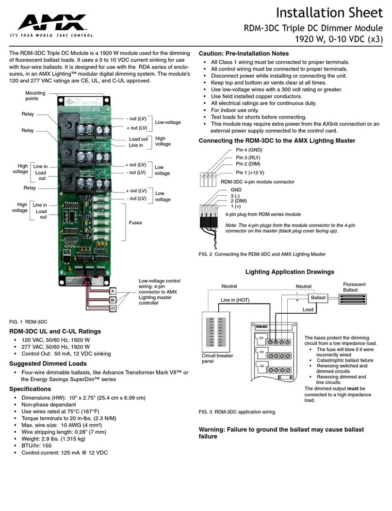
● Insert module dimmer is designed for indoor use only
● All installation on this device must be
performed by qualified or licensed electrician
● Please refer to the “Load Type Table” for proper
lighting load installation
● Metallic lighting gang box is not recommended to
use as it would shorten the RF distance
● RF distance would be affected by specific material,
such as mirror, metal, or high power electronic devices
Caution Product introduction
Insert module dimmer is designed to operate without
neutral wire. It operates with different loads, including
Incandescent lamps, halogen lamps, dimmable LED,
other dimmable loadings. This device is compatible
with standard Z-wave gateway or devices for remote
control & interoperation
:Momentary Switch
:Rocker Switch
Load Type Table
Type of Load
Incandescent Lamp
Dimmable LED
Dimmable electronic
transformer for LED
Min. Load
25W
12W
20W
300W
120W
240W
Max. Load
Halogen Lamp 20W 240W
If the lighting load is less than the required minimum loading,
please add “power stabilizer” into the circuit according to
below diagram:
LED 2
NOTE:
Power stabilizer is n ot included
on this product, Plea se contact local
sales representat ive for detail
Technical Specification
Model
Power Supply
Type of Loads
Dimensions
Temperature
Radio Frequency
RF distance
IMZ1210
AC 230V 50HZ
Refer to Load Type Table
48*46*18mm
0~40℃
Up to 40m indoors
RF dis tance w ould be a ffect ed by specific material,
*
such a s mirro r, meta l, or hig h power e lectronic devices
LED Indication
(Note:Quick Flash (4 times per second); Slow Flash (1 per sec)
Flash once Light On / Light Off
Light up for 3 seconds
Device Inclusion / Exclusion
Live
Red
Powe r stabi lizer
Neut ral
Whit e
VER 1.1
Step 5: Ensure there is no short circuit or wrong wiring
collection.
Turn on the Miniature Circuit Breaker (MCB)
Step 6: Device Inclusion/exclusion
Step 4: Select load/switch types
1. Set the gateway in device inclusion/exclusion mode
2. Quick press the Program button 3 times,the LED quick
flash 3 times to enter “Device Inclusion/exclusion”mode.
LED light up for 3 seconds to indicate device inclusion
completed.
Note: If inclusion failed, please reset the device by pressing
the program button for 10 seconds and retry for device inclusion.
Sele ction o f
load ing typ es
Rock er Swit ch
Mome ntary S witch
Sele ction o f
swit ch pane l types
Supported types of switch panel:
Sele ction o f
load ing typ es
Load
Conn ector f or
swit ch pane l
Indi cator P rogra m butto n
Ante nna Liv e
Mome ntary S witch
Rock er Swit ch
Sele ction o f switc h
pane l types
Installation
Caution: All installation on this device must be
performed by qualified or licensed electrician
Step 2 : Remove the switching panel
Step 1 : Make sure to turn off the Miniature
Circuit Breaker (MCB ) before the installation
1 2
OFF
Load
Live
868.40-869.85MHZ EU 919.70MHZ KR 865 .20 MHZ I N
908.40-916.00MHZ US 919.80-918.2 MHZ H K
(Refere nce by PHILI PS lightin g devices)
Quick Flash 3 times
Slow Flash 3 times Setup Mode
Quick Flash Continuously
Overheat protection activated
Step 3a : Wiring Connection (Rocker Switch)
1. Live wire connect to " L " through red wire
2. Lighting Load wire connect to " " through white wire
3. Select “ two wire connect“ for rocker switch
4. Connect the switching panel with two gray wires
Step 3b :Wiring Connection (Momentary Switch)
1. Live wire connect to " L " through red wire
2. Load wire connect to" " through white wire
3. Select "four wire connect" for momentary switch
4. Connect the switching panel with white wires (Dim Up button)
5. Connect the switching panel with grey wires (Dim Down button)
Live
White
Red
Load
Rocker S wi tc h
Dim Down
Dim Up
Momentar y Sw it ch
Dim Down
Dim Up
Gray White
Live
Load
White
Red
Two Wi re
Conn ector
Four W ire
Conn ector
Gray
Device Inclusion /
Exclusion Completed
Setting Completed
Reset Completed
Frequently Asked Questions
Device
inclusion
failed
Device already
included in other
gateway
Problems Possible Reasons Possible Solution
Reset to factory default
Remote
control
failed
Wireless
Signal Unstable
Please check the network,
make sure the distance
between the device and the
gateway is with in the
designed range.
Z-wave Repeater may need
if the range is out of
specification.
Wrong wiring
connection
Failed to
turn on
the light
Please check the wiring
connection and ensure it is
connected according to
the instruction
Wrong wiring
connection
Controlled by
other interoperate
from other devices
in the system
Please check the wiring
connection and ensure it is
connected according to
the instruction
Ensure there is no conflict
in interoperation setting
Indicator
quick flash
continuously
Loading is too
large &
overheated.
Overheated
caused by
other reasons
Replace a proper loading
according to the load
type table
Turn off the light for a
period of time.
If the problem still appear,
the lighting load has been
damaged, please replace
a new lighting load.
Loading is less
than there quired
minimum load
Replace a proper loading
according to the load type
table
Light flash
or turn off
automatically
Problems Possible Reasons Possible Solution
Operating Instruction:
For Rocker Switch
ON/OFF:Turn on or off the light by press button on the switch
(Default Turn on brightness = 100%, it can be de fin ed by g ate way )
Dimming:Not supported by Rocker Switch and this function
must be done by gateway
For Momentary Switch
ON/OFFTurn on or off the light by short press any button on
the switch (Default Turn on brightness = 100%, it can be defin ed by g ate way )
Dimming UP: Long press the Dim Up button to adjust to the
desired brightness
Dimming DOWN: Long press the Dim Down button to adjust
to the desired brightness
Maximum Brightness: Double press the Dim Up button
Minimum Brightness: Double press the Dim Down button
1. Stick the antenna inside the gang box.
2. Put the insert module into the gang box.
3. Install the switching panel
Step 7: Completion
Note:Please ensure normal operation before fixing the
switching panel
2
3
1
Ante nna
Maximum brightness / Minimum Brightness Setting
(App lic able to M omentary S witch Only )
● Enter the setup mode: long press Dim Up and Dim Down
buttons for 5 seconds until the light bulb flash 1 time
( LED in dicat or will s low fla sh 3 times)
● Release the buttons and enter the setup mode.
(Bri ghtne ss of lig ht bulb i s in 50% th is moment)
● Setting Max brightness: press the Dim Up button to adjust
the desired brightness.
or
● Setting Min brightness: press the Dim Down button to
adjust the desired brightness.
● Exit the setup mode: long press Dim Up and Dim Down
buttons for 5 seconds until the light bulb turn off and
flash 1 time( LE D indicato r will Li ght up for 3 sec onds).
Factory Default Reset
Long press the program button for 10 seconds.
LED will Light up for 3 seconds once reset completed.
● Maximum brightness and Minimu m bri ght nes s: fa cto ry default 100% and 20%
● Turn on brightness: factory defaul t 100 %
Advanced Setting:
LED 2
LED 1
LED 2
LED 1
LED 1
Hereby, Airline Mechanical Company Ltd , declares that
this Insert module dimmer is in compliance with the
essential requirements and other relevant provisions of
Directive 2014/53/EU.
The full test of the EU declaration of conformity is available
at the following internet address: www.tronico.com.hk
Maximum RF
Power 4dBm

