© 2016 TOPGREENER, Inc. ● CA, U.S.A. ● WWW.TOPGREENER.COM ● 0205180117-02
INSTALLATION INSTRUCTIONS
Voltage .........................................................................................................120VAC, 60Hz
Incandescent/ Halogen................................................................................................600W
Dimmable LED and Dimmable CFL............................................................................150W
Operating Temperature......................................................................................32°F-104°F
This device is warranted to be free of material and workmanship defects for 1 year from the date of purchase. Original receipt or proof of purchase from an authorized retailer must be presented upon warranty claim. ALL claims must
be verified and approved by Top Greener, Inc. Warranties from other Top Greener products may vary. This warranty is nontransferable and does not cover normal wear and tear or any malfunction, failure, or defect resulting from
misuse, abuse, neglect, alteration, modification, or improper installation. To the fullest extent permitted by the applicable state law, Top Greener shall not be liable to the purchaser or end user customer of Top Greener products for
direct, indirect, incidental, or consequential damages even if Top Greener has been advised of the possibility of such damages. Top Greener’s total liability under this or any other warranty, express or implied, is limited to repair,
replacement or refund. Repair, replacement or refund are the sole and exclusive remedies for breach of warranty or any other legal theory.
Model: TGWF3K
3-Way Add-on Switch
This cannot be used as a standalone switch. Requires connection with
TGWF500D or TGWF15S (not included). Neutral Wire Required.
SPECIFICATIONS
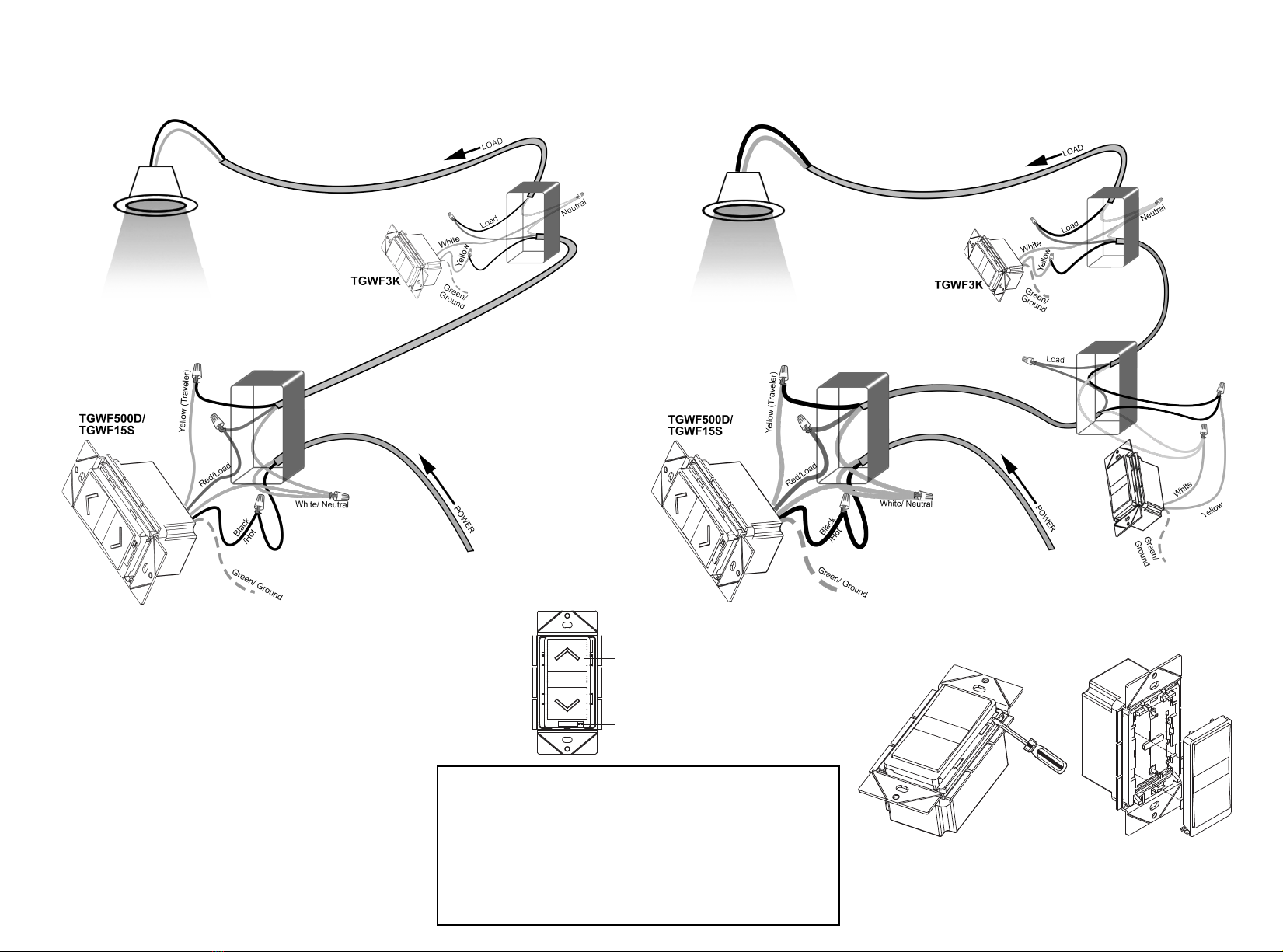
WIRING for TGWF3K AUXILIARY SWITCH
PRODUCT NOTES
The TGWF3K is a Remote Add-on Dimmer Switch that is designed for installation with the
TGWF500D. Traditional dimmers only allows you to dim the lights from one location and
turn the lights on/off from other locations. The TGWF3K's remarkable design allows you to
have full dimming and on/off control of the lights from multiple locations.
Follow the diagrams in this manual to connect the main dimmer (model TGWF500D or
TGWF15S not included) and the add-on dimmers to multiple locations.
WARRANTY
WARNING
Turn the POWER OFF at the circuit breaker before installing the Dimmer
Read and understand these instructions before installing. This device is intended for installation
in accordance with the National Electric Code and local regulations. It is recommended that a
qualified electrician performs this installation.
Use copper wire only
Use Wires with Minimum Temperature Rating 75°C (167°F)
Common 3-Way wiring: 3-way switches are commonly wired as depicted
below with the Power "LINE" entering the electrical wall box at one
location, then connected to a second location with a 3 conductor (14-3 or
12-3 cable), and lastly connected to the light (or LOAD) by a 2 conductor
(14-2 or 12-2 cable).
This diagram is to be used only as a guide for what to expect when the
existing switches are removed from the walls.
TRAVELER 1
TRAVELER 2
HOT
NEUTRAL
GROUND
LOAD
SWITCH
1
SWITCH
2
LINE
White (Neutral)
Traveler(Yellow)Red (Load)
TGWF3K TGWF500D
Green (Ground)
Black (Hot)
New construction wiring: The diagram below shows the wiring for new
constructions. This wiring method requires the LINE and LOAD wires to
connect to the primary switch, TGWF500D or TGWF15S (not included).
To connect the TGWF3K to a primary switch
(TGWF500D or TGWF15S) using the existing
wires in the wall, follow the wiring diagrams on the
next page.
FCC COMPLIANCE STATEMENT
FCC Grant of Equipment Authorizations of this device and transmitters installed in this device can be found at FCC website by entering the FCC ID number
on the device.
Caution: Changes or modifications not expressly approved by the part responsible for compliance could void the user’s right to operate the equipment.
This device complies with Part 15 of the FCC Rules. Operation is subject to the following two conditions: (1) this device may not cause harmful interference,
and (2) this device must accept any interference received, including interference that may cause undesired operation of the device.
This equipment has been tested and found to comply with the limits for a Class B digital device, pursuant to part 15 of the FCC rules. These limits are
designed to provide reasonable protection against harmful interference in a residential installation. This equipment generates, uses and can radiate radio
frequency energy and, if not installed and used in accordance with the instructions, may cause harmful interference to radio communications. However, there
is no guarantee that interference will not occur in a particular installation. If this equipment does cause harmful interference to radio or television reception,
which can be determined by turning the equipment off and on, the user is encouraged to try to correct the interference by one or more of the following
measures:
•Reorient or relocate the receiving antenna.
•Increase the separation between the equipment and receiver.
•Connect the equipment into an outlet on a circuit different from that to which the receiver is
connected.
•Consult the dealer or an experienced radio/TV technician for help.