manuals.online logo
Brands
  1. Home
  2. •
  3. Brands
  4. •
  5. Schaudt
  6. •
  7. Dimmer
  8. •
  9. Schaudt LIS 101 Service manual

Schaudt LIS 101 Service manual

Date: 28.02.2011
ESchaudt GmbH, Elektrotechnik und Apparatebau, Planckstraße 8, 88677 Markdorf, Germany, Tel. +49 7544 9577-0, Fax +49 7544 9577-29, www.schaudt--gmbh.de
822.381 BAMA / EN
Operation and assembly instructions
for LIS 101
1 Instruction Manual
1.1 Introduction
This instruction manual contains important information on the safe operation
of equipment supplied by Schaudt. Make sure you read and follow the safety
instructions provided.
The instruction manual should be kept in the vehicle at all times. Ensure that
other users are made aware of the safety regulations.
1.2 Operation
The LIS 101 dimmer itself has no controls. The lighting is controlled with the
light switch(es) connected as follows:
"
Briefly press the light switch.
F
The light circuit is enabled.
"
Briefly re-press the light switch.
F
The light circuit is disabled.
The light circuit is initially disabled.
"
Press light switch and keep pressed (longer than about 1 second).
F
Dimming starts with the minimum brightness (approx. 20%).
F
The light becomes brighter slowly until the maximum brightness is re-
ached.
Y
The dimming direction (brighter or darker) changes every time a light
switch is pressed.
"
Release the light switch of the light circuit.
F
The brightness stays on the current brightness.
Y
If the light switch is pressed and kept pressed when the lamps were on:
F
the lamps become darker if lit with maximum brightness.
F
the lamps are dimmed further (brighter or darker) if they were already
dimmed.
F
the lamps become brighter if lit with minimum brightness.
Switching on and off
Dimming
Operating Instructions for LIS 101 Light Control System
2
Date: 28.02.2011 822.381 BAMA / EN
1.3 System faults
The majority of faults are caused by blown fuses.
Please contact our customer service address if you cannot rectify the fault
using the following table.
Y
ATTENTION!
The LIS 101 dimmer can be damaged beyond repair by overloading. So:
F
Only replace defective fuses when the dimmer is not live and the
cause of the blown fuse is known.
F
Never bypass or repair defective fuses.
Fault Possible cause Remedy
Lighting connected does
not work.
No 12V supply. Check and switch on
supply voltage.
Check and replace fuse.
LIS 101 defective. Replace LIS 101.
Wiring defective. Check/replace connector
cable and 6.3mm
connector.
Short-circuit at output. Rectify short-circuit.
Connected lighting goes
out briefly and then goes
on again automatically.
Internal temperature
monitor activated.
Check lighting connected:
Maximum power of 120W
may not be exceeded.
1.4 Maintenance
The dimmer requires no maintenance.
2 Installation instructions
2.1 Mechanical installation
The device is designed for wall or floor installation.
"
Select a dry place for installation.
"
Ensure a minimum clearance to the surrounding fixtures and fittings:
F
Maintain a gap of at least 2cm on all sides (except mounted side).
F
Whilst in operation, the ambient temperature must not exceed +45 °C,
measured 1cm away from the sides of the device.
"
Use two screws (diameter 2.5mm) to screw the dimmer to a stable and
level surface (at the two attachment holes provided).
Flat
vehicle fuses
Environment
Minimum clearance
Fitting
Operating Instructions for LIS 101 Light Control System
3
Date: 28.02.2011
822.381 BAMA / EN
for attachment screw
Top
view
Front of device
45 12
54
24
68
1,5 2x ∅3
5x soldered--in blade terminals
straight 6.3 x 0.8
Fig. 1 Dimensional diagram of LIS 101 dimmer (dimensions in mm)
2.2 Electrical connection
Y
ATTENTION!
A fuse with a maximum rating of 10A must be inserted into the supply line to
prevent overloading.
Y
ATTENTION!
The ”Switch” input of the dimmer can be activated with either ”+12 V” or ”Mi-
nus”. A mixed connection of switches is not permitted for the connection of
multiple switches. Several switches being pressed at the same time would
lead to a short circuit.
For activation via ”+12 V”, the wire cross-section to the connector of the but-
tonmustbeselectedsufficientlylargeinlinewithfuseF1.
+--
12V supply
LIS 101
Lighting
--
+
Light switch
Fuse F1
max. 10A
5 blade receptacles, 6.3mm
*
* connect either to +12 V
or Minus
Fig. 1 LIS 101 dimmer circuit diagram
Y
ATTENTION!
An incorrect connection (e.g. reverse poling) may result in irreparable da-
mage to the device.
Operating Instructions for LIS 101 Light Control System
4
Date: 28.02.2011 822.381 BAMA / EN
Y
Only buttons (closers) and no switches may be used for the connection.
Buttons automatically return to their original state after being pressed.
Connect the dimmer in the following order (also refer to circuit diagram):
1. Disable 12V supply.
2. Directly connect the lighting to the LIS 101 dimmer with a 2-wire cable.
3. Connect one (or more) light switches as follows:
F
Connect one lead of the button to the Minus ”--” or the ”+12V” of the
12V supply
F
Connect the other lead of the button to the ”Taster” connector on the
LIS 101 dimmer.
F
If available, connect any further buttons in the same way (parallel).
4. Connect the Plus ”+” of the supply to ”+12V” on the LIS 101 dimmer.
5. Connect the Minus ”--” of the supply to ”-- Minus” on the LIS 101 dimmer.
2.3 Technical details
2.3.1 Mechanical data
68x23x57(WxHxDinmm)
40g
Black plastic
2.3.2 Electrical details
for 12V DC systems (10.5 to 15V)
max. 10 A
max. 5mA
2.3.3 Environmental parameters
-10 °Cto+45 °C
-20 °Cto+70°C
Operation in dry environment only
CE marked
Connection sequence
Dimensions
Weight
Housing
Operating voltage
Current
Standby current
(lighting off)
Operating temperature
Storage temperature
Humidity
CE

Popular Dimmer manuals by other brands

FABAS LUCE SMART LUCE 3572-00-006 Assembly instructions

FABAS LUCE

FABAS LUCE SMART LUCE 3572-00-006 Assembly instructions

Bodine B463 installation instructions

Bodine

Bodine B463 installation instructions

Hamilton H-LED-STAT Installation note

Hamilton

Hamilton H-LED-STAT Installation note

EUCHIPS Walldim 105 quick start guide

EUCHIPS

EUCHIPS Walldim 105 quick start guide

Leviton Decora Illumatech RPI06-10 installation instructions

Leviton

Leviton Decora Illumatech RPI06-10 installation instructions

INSTEON LampLinc 2457D2 owner's manual

INSTEON

INSTEON LampLinc 2457D2 owner's manual

Ostermann EasyOne 508.4040 user manual

Ostermann

Ostermann EasyOne 508.4040 user manual

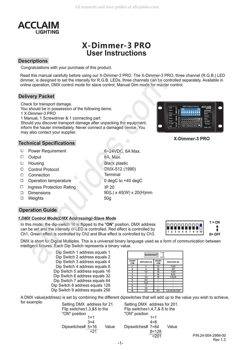
Acclaim Lighting X-Dimmer-3 PRO User instructions

Acclaim Lighting

Acclaim Lighting X-Dimmer-3 PRO User instructions

Vadsbo LDN200KRON installation manual

Vadsbo

Vadsbo LDN200KRON installation manual

retrotouch RTS2030 instruction manual

retrotouch

retrotouch RTS2030 instruction manual

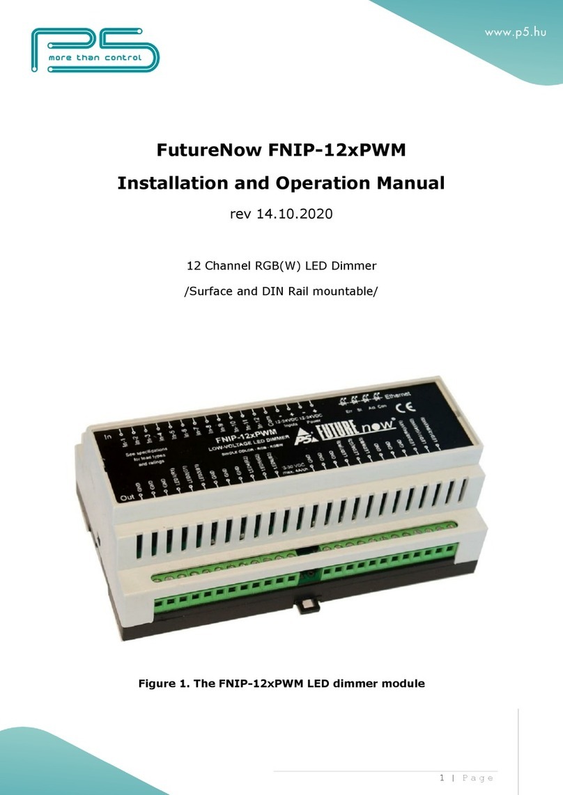
p5 FNIP-12xPWM Installation and operation manual

p5

p5 FNIP-12xPWM Installation and operation manual

PXM PX155 user manual

PXM

PXM PX155 user manual

Leviton Decora Smart D26HD user manual

Leviton

Leviton Decora Smart D26HD user manual

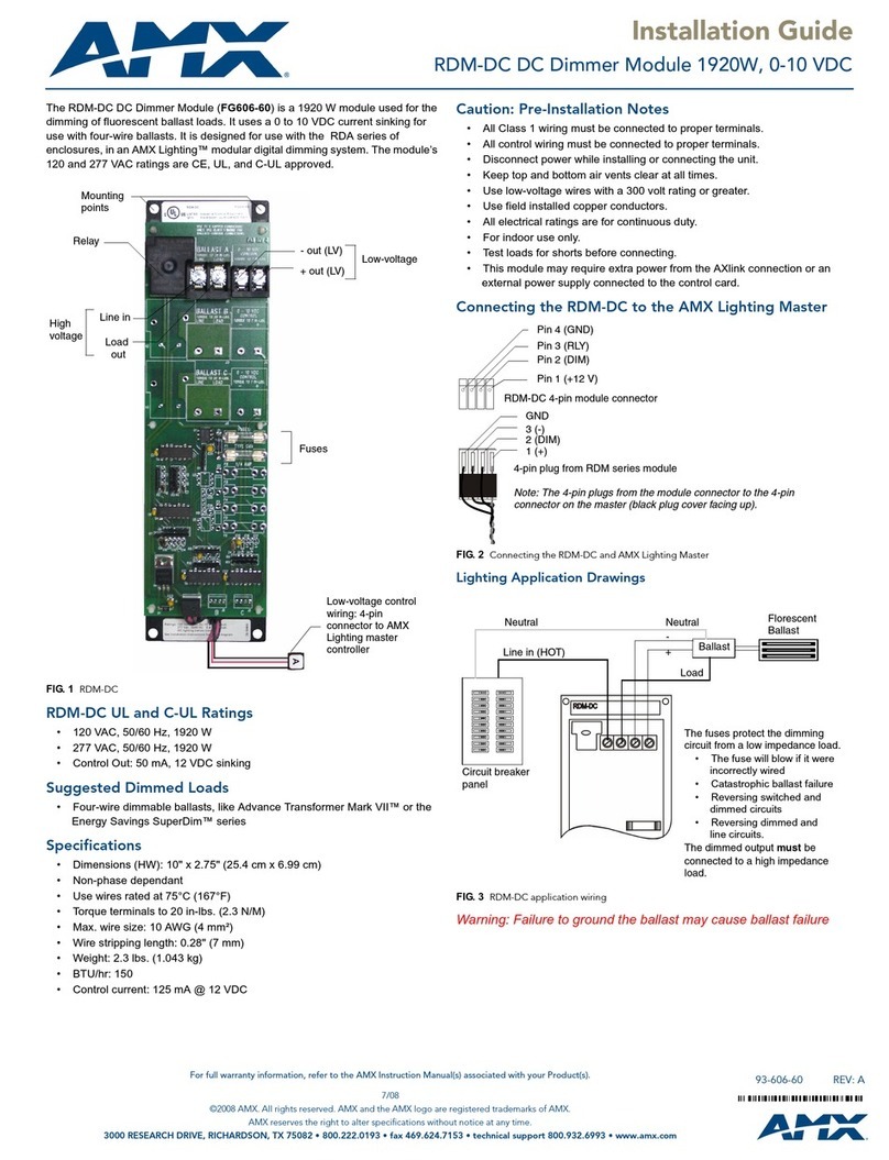
AMX RDM-DC DC MODULE Installation sheet

AMX

AMX RDM-DC DC MODULE Installation sheet

Clas Ohlson EF700DD manual

Clas Ohlson

Clas Ohlson EF700DD manual

Elko SmartMove Multiwire Dimmer Push user guide

Elko

Elko SmartMove Multiwire Dimmer Push user guide

Lite-Puter AX-1205 user manual

Lite-Puter

Lite-Puter AX-1205 user manual

preussen DimME KNX product manual

preussen

preussen DimME KNX product manual

manuals.online logo
manuals.online logoBrands
  • About & Mission
  • Contact us
  • Privacy Policy
  • Terms and Conditions

Copyright 2025 Manuals.Online. All Rights Reserved.