Trox Technik PURELINE50 User manual
Product overview
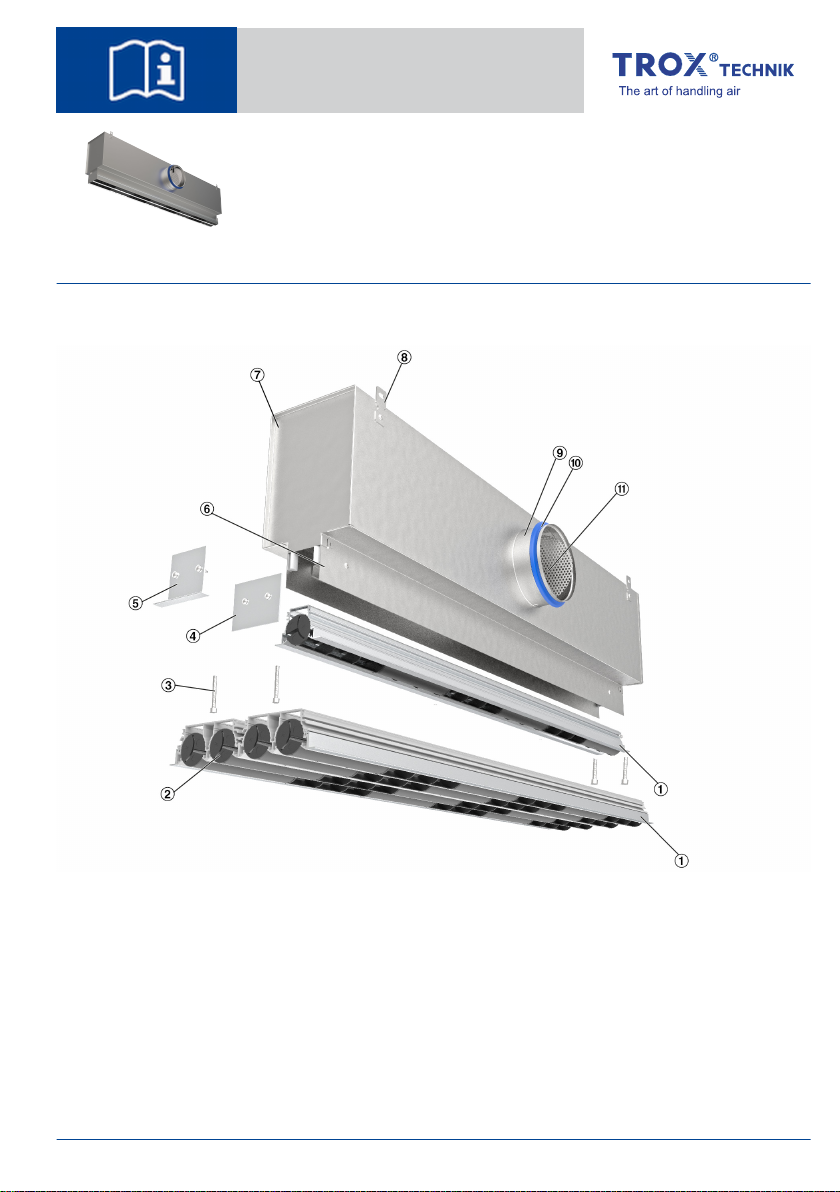
Fig. 1: Schematic illustration of PL50-*-SF
①Diffuser face (with 1- to 4‑slots)
②Adjustable air control element
③Screw fixing
④End plate
⑤End angle
⑥Neck
⑦Plenum box
⑧Suspension lug
⑨Connector
⑩Lip seal
⑪Damper unit for volume flow rate balancing
Optional equipment: ③ ④ ⑤ ⑩ ⑪
Installation instructions GB/en
Air diffusers
Slot Diffusers Type PURELINE50
TROX GmbH
Heinrich-Trox-Platz
47504 Neukirchen-Vluyn, Ger-
many
Germany
Phone: +49 (0) 2845 2020
Fax: +49 (0) 2845 202265
E-mail: [email protected]
http://www.troxtechnik.com
A00000079622, 03/2021, © 2021 TROX GmbH
Air diffusers Slot Diffusers Type PURELINE50 1

Important notes
Information on the installation manual
This manual enables operating or service personnel
to correctly install the product described below and
to use it safely and efficiently.
It is essential that these individuals read and fully
understand this manual before starting any work.
The basic prerequisite for safe working is to comply
with the safety notes and all instructions in this
manual.
The local regulations for health and safety at work
and general safety regulations also apply.
Qualified staff
Specialist personnel
Specialist personnel are individuals who have suffi-
cient professional or technical training, knowledge
and actual experience to enable them to carry out
their assigned duties, understand any potential haz-
ards related to the work under consideration, and
recognise and avoid any risks involved.
Limitation of liability
The information in this manual has been compiled
with reference to the applicable standards and
guidelines, the state of the art, and our expertise
and experience of many years.
The manufacturer does not accept any liability for
damages resulting from:
Non-compliance with this manual
Incorrect use
Operation or handling by untrained individuals
Unauthorised modifications
The actual scope of delivery may differ from the
information in this manual for special constructions,
additional order options or as a result of recent
technical changes.
Personal protective equipment
Personal protective equipment must be worn for
any work in order to reduce health or safety haz-
ards to the minimum.
The appropriate protective equipment for a job must
be worn for as long as the job takes.
Industrial safety helmet
Industrial safety helmets protect the head from
falling objects, suspended loads, and the effects of
striking the head against stationary objects.
Protective gloves
Protective gloves protect hands from friction, abra-
sions, punctures, deep cuts, and direct contact with
hot surfaces.
Safety shoes
Safety shoes protect the feet from crushing, falling
parts and prevent slipping on a slippery floor.
Correct use
Air terminal devices are used for the ventilation of
internal spaces in industrial and comfort areas. The
air terminal devices are connected to a supply air or
extract air system (by others), which is typically
connected to an air handling unit.
Air terminal devices supply cold or warm air to
rooms (within the stated supply air to room air tem-
perature differences).
Installation, operation and maintenance may have
to meet increased hygiene requirements for certain
areas of application.
Important notes
Air diffusers Slot Diffusers Type PURELINE502
The installation of air terminal devices in humid
rooms, areas with potentially explosive atmos-
pheres or rooms with dust-laden or aggressive air
has to be assessed for each individual case.
Transport and storage
Delivery check
Upon delivery, carefully remove the packaging and
check the unit for transport damage and complete-
ness. In case of any damage or an incomplete ship-
ment, contact the shipping company and your sup-
plier immediately. Put the product back into its
packaging after the delivery check to protect it from
dust and contamination.
Fixing and installation material
Fixing and installation material is not part of the
supply package (unless stated otherwise), but
has to be provided by others; it has to be suitable
for the installation situation.
Factory setting
The air control elements are factory set to a cer-
tain position. Changing this factory setting
increases the commissioning time and cost. Be
careful when you unpack and install the air con-
trol elements so as not to accidentally change
their position.
Transport on site
CAUTION!
Danger of injury from sharp edges, sharp cor-
ners and thin sheet metal parts!
Sharp edges, sharp corners and thin sheet metal
parts may cause cuts or grazes.
– Be careful when carrying out any work.
– Wear protective gloves, safety shoes and a
hard hat.
Please note:
Be careful when unloading or moving the
product, and pay attention to the symbols and
information on the packaging.
If possible, take the product in its transport
packaging up to the installation location.
Use only lifting and transport gear designed for
the required load.
Always secure the load against tipping and
falling.
Do not move bulky items just by yourself. Get
help to prevent injuries and damage.
Storage
Please note:
Store the product only in its original packaging
Protect the product from the effects of weather
Protect the product from humidity, dust and
contamination
Storage temperature: -10 °C to 50 °C.
Relative humidity: 95% max., no condensation
Packaging
Properly dispose of packaging material.
Transport and storage
Air diffusers Slot Diffusers Type PURELINE50 3
Technical data
Dimensions and weight
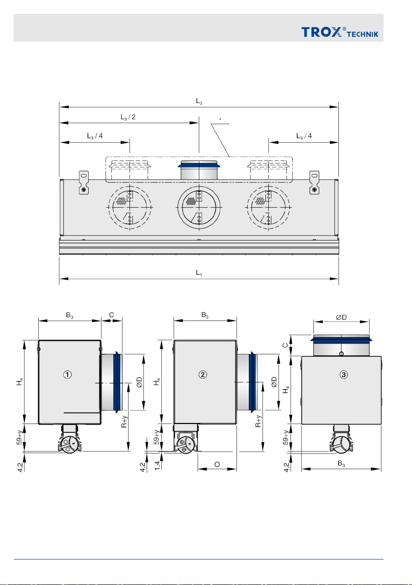
Fig. 2: Dimensions and spigot arrangement, * spigot arrangement for construction VS
Fig. 3: Plenum box variants
1 PL50-*-HS (symmetric position of plenum box, side entry spigot)
2 PL50-*-HA (asymmetric position of plenum box, side entry spigot)
3 PL50-*-VS (symmetric position of plenum box, top entry spigot)
Technical data
Air diffusers Slot Diffusers Type PURELINE504

Nominal length L1 [mm] L3 [mm]
600 600 595
750 750 745
900 900 895
1050 1050 1045
1200 1200 1195
1350 1350 1345
1500 1500 1495
1650 1650 1645
1800 1800 1795
1950 1950 1945
Variant B3 [mm] H4 [mm]
HS/HA VS HS/HA VS
PL50-1 138 176 185 150
PL50-2 183 214 225
PL50-3 238 270 275 175
PL50-4 278 335 340 210
Variant R [mm] O [mm]
PF-HA SF-HA
PL50-1 152 + Y 98 84
PL50-2 172 + Y
PL50-3 197 + Y 82
PL50-4 229 + Y
Neck extension Y = 0 / 22 / 47 / 72 / 97 / 121
Variant ØD [mm] C [mm]
PL50-1 123 48
158 50
PL50-2 158
198
PL50-3 198
248 48
PL50-4 248 48
313 50
Diffuser faces
Fig. 4: PL50-4 (without extended border)
Fig. 5: PL50-4/B00 (with extended border)
Fig. 6: PL50-4-DF/.../B00
Variant M P A
[mm]
PL50-1 50 70 56
PL50-2 95 115 101
PL50-3 150 170 156
PL50-4 190 210 196
Technical data
Air diffusers Slot Diffusers Type PURELINE50 5
Plenum box var-
iant
Weight [kg/m]
Number of slots
1 2 3 4
Diffuser face 1.0 1.6 3.1 3.4
Plenum box
HS/HA
4.1 5.1 6.1 7.3
Plenum box
HS/HA+L (lining)
4.8 6.0 7.2 8.5
Plenum box VS 4.8 5.2 6.0 7.3
Plenum box VS+L
(lining)
5.9 6.3 7.2 8.2
Total weight [kg] =
Weight of diffuser face × L1
+ Weight of plenum box × L3
Enter lengths in [m]
Technical data
Nominal lengths 600 – 1950 mm, in incre-
ments of 150 mm
Number of slots 1, 2, 3 or 4
Minimum volume flow rate,
with ∆tz = –10 K
10 l/s or 36 m³/h
Maximum volume flow rate,
with LWA ≅ 50 dB(A)
608 l/s or 2190 m³/h
Supply air to room air tem-
perature difference
–10 to +10 K
Assembly
General information
Personnel:
Specialist personnel
Protective equipment:
Industrial safety helmet
Protective gloves
Safety shoes
Note:
For room heights up to 4 m (lower edge of sus-
pended ceiling)
Flush ceiling installation
Fix the product only to load-bearing structural
elements.
Load suspension systems only with the weight
of the product. Adjacent components and con-
necting ducts must be supported separately.
The air terminal devices must remain acces-
sible for cleaning even after installation.
Installation and sealing material which the
manufacturer provides is usually supplied in an
extra bag.
Before you install the product, take suitable precau-
tions to protect air distribution components from
contamination during installation (VDI 6022). If this
is not possible, at least cover the product or take
other precautions to protect it from contamination.
In this case you have to ensure that the product
cannot be started. Ensure that all components are
clean before you install them. If necessary, clean
them thoroughly. If you have to interrupt the installa-
tion procedure, protect all openings from the
ingress of dust or moisture.
Fig. 7: Position of plenum box
If (L3+ 5) < L1, the plenum box can be positioned to
the left, to the right or in the centre.
Assembly
Air diffusers Slot Diffusers Type PURELINE506

Ceiling installation
If possible, install the device before fixing the ceiling
tiles; if this is not possible, remove the adjacent
ceiling tiles.
Use only approved and adequately sized suspen-
sion systems (fixing material is not included in the
supply package). Dimensions and weight
Ä
Chapter 4 ‘Technical data’ on page 4.
If you have to install larger devices, it is best to
either ask someone to give you a hand or use a lift.
Fig. 8: Plenum box suspension
Variant A [mm] L3
HS/HA VS
PL50-1 178 216
Ä
Table on page 5
PL50-2 223 254
PL50-3 278 310
PL50-4 318 375
1. Fix the suspension parts such as ropes,
cables or metal hangers (Fig. 8/1) to the
ceiling.
2. Turn up the suspension lugs.
3. Use all of the available suspension points on
the plenum box.
Linear run
Fig. 9: Linking slot diffusers
4. The supplied alignment plates (Fig. 9/1) help
you align slot diffusers for a continuous
linear arrangement.
Fix an alignment plate (2 each per diffuser)
on one side, then connect the next diffuser
to it.
Assembly
Air diffusers Slot Diffusers Type PURELINE50 7
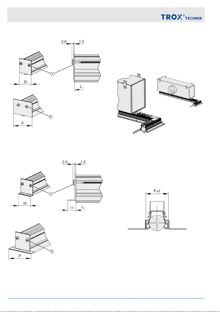
Fixing EP end plates
Fig. 10: EP end plate without and with extended
border
Fixing EA end angles
Fig. 11: EA end angle without and with extended
border
Single diffusers are factory fitted with end plates or
end angles. For a continuous linear arrangement,
they must be fitted by others. The end plates or end
angles must be fitted with screws (Fig. 10/1 and
Fig. 11/1).
Connecting corner sections
Fig. 12: Fitting a corner section with extended
border
Corner sections are supplied with two alignment
plates.
Installation in panelled ceilings
Fig. 13: Installation without extended border into a
ceiling with rectangular panels; required length of
installation opening when an end plate is used:
L1 + 9
Assembly
Air diffusers Slot Diffusers Type PURELINE508
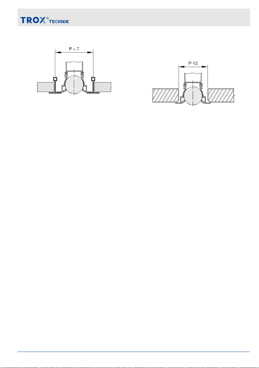
T-bar ceiling
Fig. 14: Installation with extended border into a T-
bar ceiling; required length of installation opening
when an end angle is used: L1 + 29
Installation in continuous ceilings
Fig. 15: Installation with extended border into a con-
tinuous ceiling; required length of installation
opening when an end angle is used: L1 + 9
Assembly
Air diffusers Slot Diffusers Type PURELINE50 9
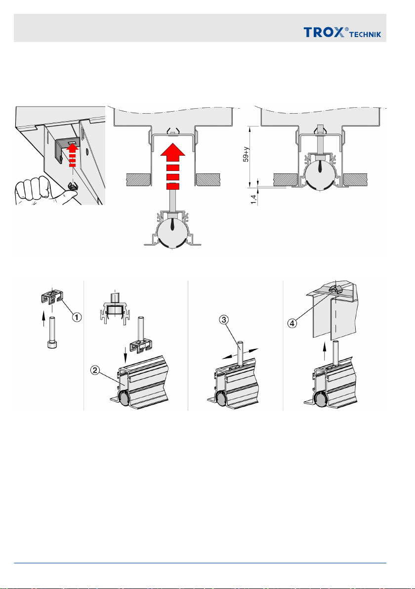
Assembling the detachable diffuser face fixing
The face of slot diffusers with detachable diffuser face fixing (variant FS or DS) can be fixed to the plenum
box after the false ceiling has been completed.
Fig. 16: PL50-1-SF
Fig. 17: Diffuser faces with detachable fixing
Assemble the fixing material as shown. The fixing material ① is supplied separately. Then insert the fixture
into the diffuser face ② and position it as required ③. Move the diffuser face towards the plenum box so
that the screws fit into the supplied fixing holes ④ in the plenum box. Using an Allen key (SW4) simplifies
the fixing procedure. To remove the diffuser face, first remove the Allen screws (SW4 Allen key).
Assembly
Air diffusers Slot Diffusers Type PURELINE5010


Retrofit of spring clip fixing DF
If required, the spring clip fixing can be retrofitted.
Assembly is carried out by others depending on the
length of the diffuser face and in accordance with
the following images. Installation of the diffuser face
into the ceiling in accordance with Fig. 18 and
Fig. 19
Fig. 20: LN 600 to 1350 mm
1 Self-drilling screw ∅3.5 - 4.5, max. length 10
mm (provided by others)
Fig. 21: LN 1500 to 1950 mm
LN Number of self-drilling
screws
B
600 - 1350 2 –
1500
3
750
1650 750
1800 900
1950 900
Duct connection
The plenum box has a spigot for duct connection.
Variants with a double lip seal allow for a sufficiently
tight connection; additional sealing is not required.
Initial commissioning, maintenance and
cleaning
Initial commissioning
Before you start commissioning:
Check that the air terminal devices are cor-
rectly seated.
Remove protective film, if any.
Ensure that all air terminal devices are clean
and free from residues and foreign matter.
Check that electrical connections (if any) have
been correctly made.
Ensure that the devices have been correctly
fixed and connected to the ducting.
For commissioning see also VDI 6022, part 1 – 'Hy-
giene requirements for ventilation and air-condi-
tioning systems and units'.
Initial commissioning, maintenance and cleaning
Air diffusers Slot Diffusers Type PURELINE5012
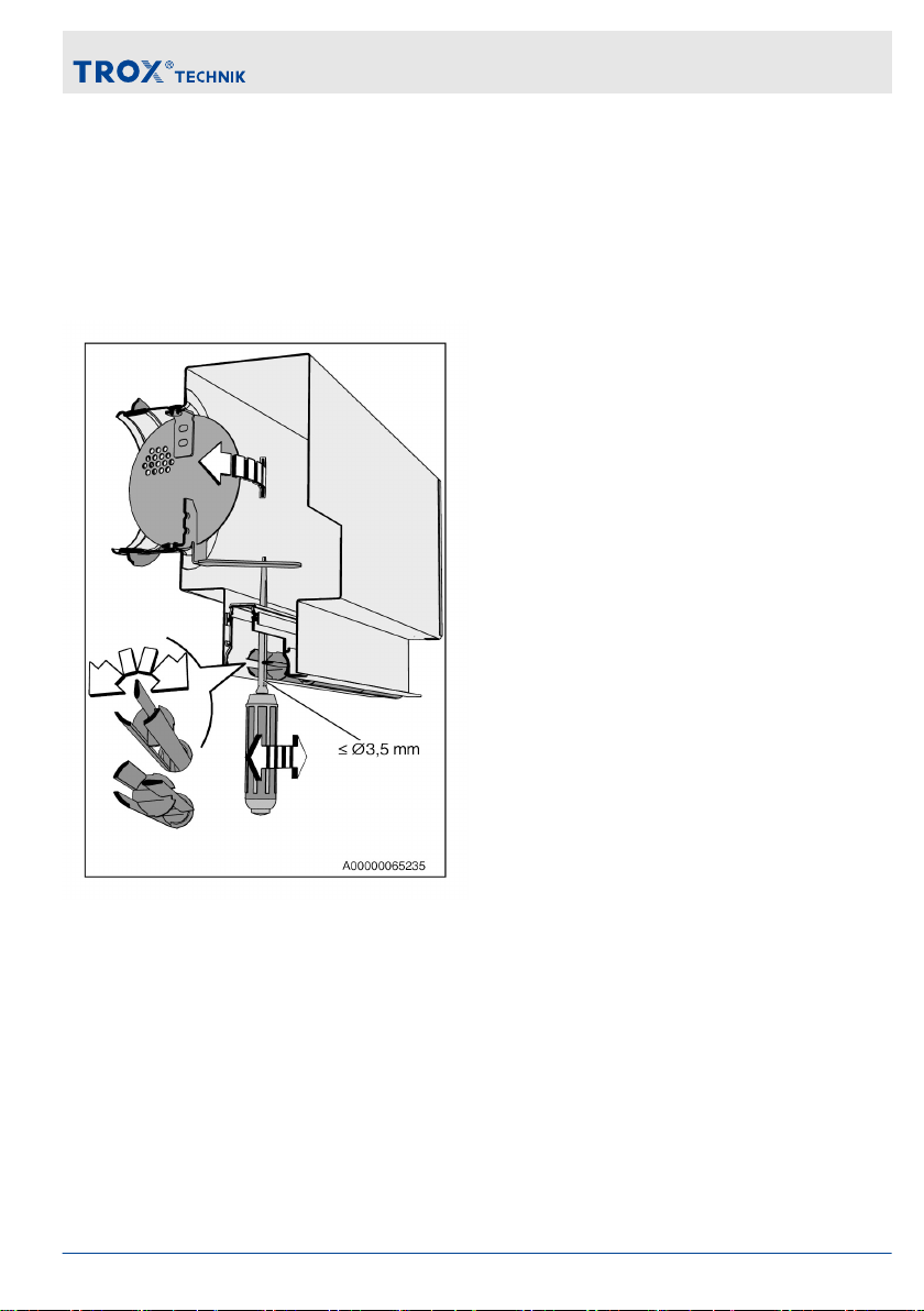
Volume flow rate balancing
When several diffusers are connected to just one
volume flow controller, it may be necessary to bal-
ance the volume flow rates.
Slot diffusers with plenum box and damper blade
(variant -D): The damper blade can be adjusted
even after the diffuser face has been installed.
Fig. 22: Setting the damper blade, e.g. with a
screwdriver
Move the air control element near the spigot in such
a way that it is possible to insert a screw driver.
Setting the air discharge direction
These are only schematic diagrams to illustrate the setting of the air control elements.
Initial commissioning, maintenance and cleaning
Air diffusers Slot Diffusers Type PURELINE50 13
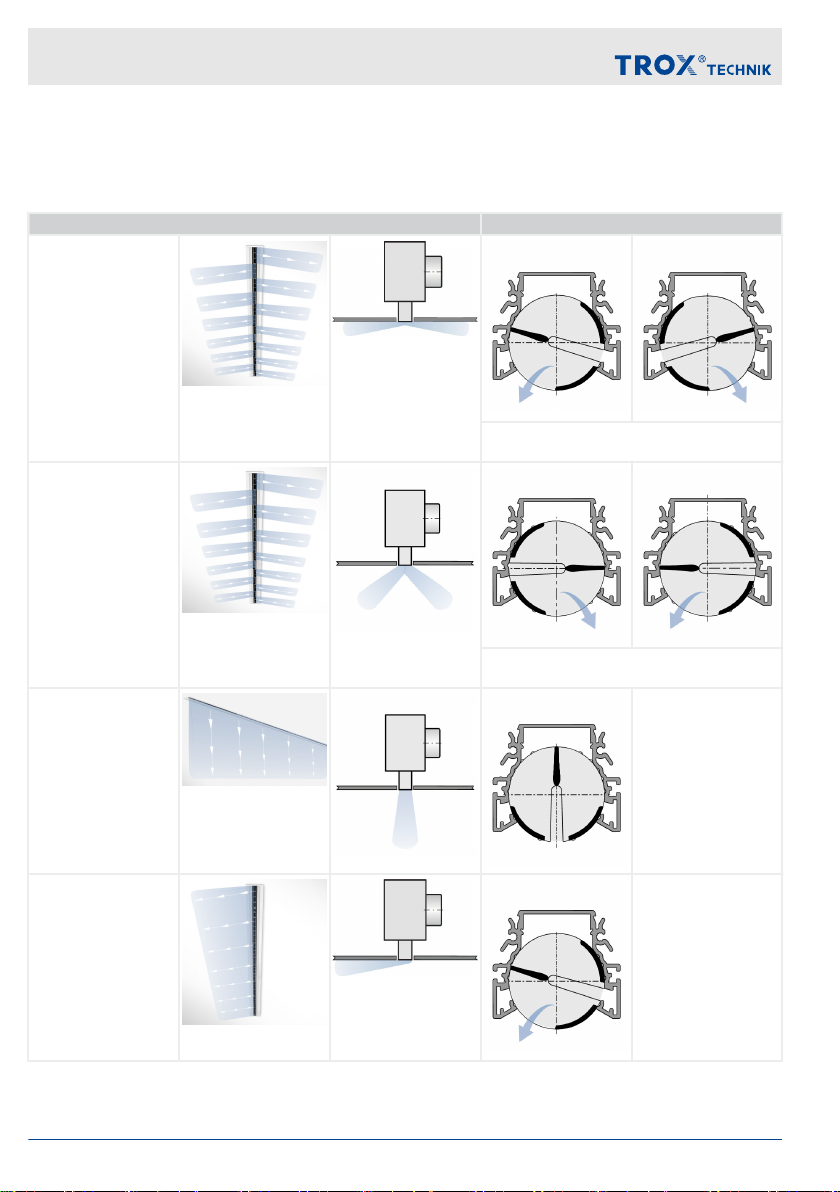
The mullions of the air control elements have grooves that make it easier to adjust the elements. We rec-
ommend you to use both hands to adjust the air control elements.
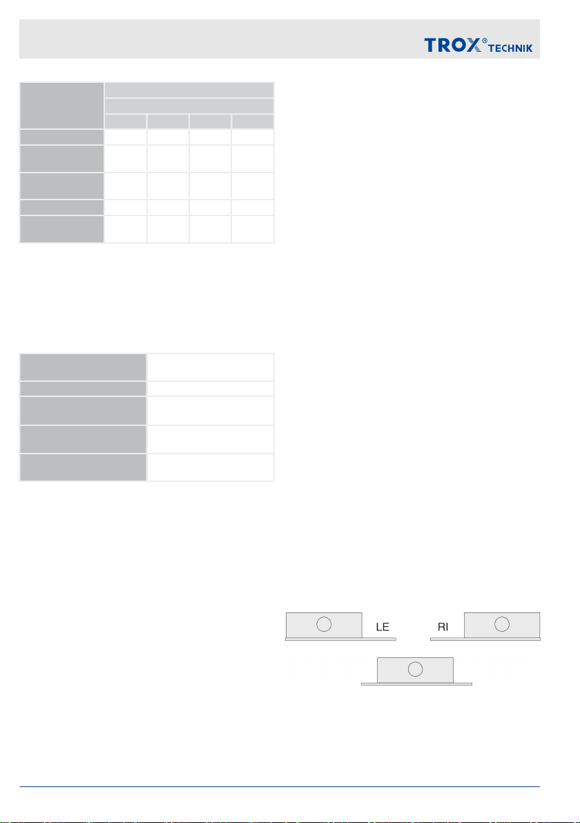
Air discharge – ceiling installation
Air discharge Setting of the air control elements
Alternating horizontal
air discharge
Alternating air control elements set to left-hand
or right-hand air discharge
Alternating angled air
discharge
Alternating air control elements set to left-hand
or right-hand air discharge
Vertical air discharge
One-way horizontal air
discharge to the left
Initial commissioning, maintenance and cleaning
Air diffusers Slot Diffusers Type PURELINE5014

Air discharge Setting of the air control elements
One-way horizontal air
discharge to the right
extract air
Maintenance and cleaning
Please note:
The cleaning intervals given in the VDI 6022
standard apply.
Clean surfaces with a damp cloth.
Use only common household cleaners, do not
use any aggressive cleaning agents.
Do not use cleaning agents that contain
chlorine.
Do not use equipment for removing stubborn
contamination, e.g. scrubbing sponges or
scouring cream, as it may damage the sur-
faces.
Initial commissioning, maintenance and cleaning
Air diffusers Slot Diffusers Type PURELINE50 15

Air diffusers Slot Diffusers Type PURELINE5016
This manual suits for next models
4
Table of contents
Other Trox Technik Air Cleaner manuals


