Troy-Bild TB144 User manual
4-Cycle Garden Cultivator
TB144
TABLE OF CONTENTS
Service Information . . . . . . . . . . . . . . . . . . . . . . . . . . . . . . . . .1
Rules for Safe Operation . . . . . . . . . . . . . . . . . . . . . . . . . . . . .2
Know Your Unit . . . . . . . . . . . . . . . . . . . . . . . . . . . . . . . . . . . .4
Assembly Instructions . . . . . . . . . . . . . . . . . . . . . . . . . . . . . . .5
Oil and Gas Information . . . . . . . . . . . . . . . . . . . . . . . . . . . . . .6
Starting/Stopping Instructions . . . . . . . . . . . . . . . . . . . . . . . . .7
Operating Instructions . . . . . . . . . . . . . . . . . . . . . . . . . . . . . . .8
Maintenance and Repair Instructions . . . . . . . . . . . . . . . . . . .9
Cleaning and Storage . . . . . . . . . . . . . . . . . . . . . . . . . . . . . .12
Troubleshooting Chart . . . . . . . . . . . . . . . . . . . . . . . . . . . . . .13
Specifications . . . . . . . . . . . . . . . . . . . . . . . . . . . . . . . . . . . .14
Warranty Information . . . . . . . . . . . . . . . . . . . . . . . . . . . . . . .16
Operator’s Manual
DO NOT RETURN
THIS PRODUCT
For Assistance please call 1-800-828-5500 (U.S.) or
1-800-668-1238 (Canada)
or visit www.troybilt.com / www.troybilt.ca
P/N 769-04266 P01 (12/08)
For service call 1-800-828-5500, or 1-800-668-1238 in Canada
to obtain a list of authorized service dealers near you. For more
details about your unit, visit our website at www.troybilt.com or
www.troybilt.ca.
DO NOT RETURN THE UNIT TO THE RETAILER. PROOF OF
PURCHASE WILL BE REQUIRED FOR WARRANTY SERVICE.
THIS PRODUCT IS COVERED BY ONE OR MORE U.S. PATENTS.
OTHER PATENTS PENDING.
Service on this unit both within and after the warranty period should
be performed only by an authorized and approved service dealer.
Copy the serial number here:
Copy the model and parent part number here:
All information, illustrations, and specifications in this manual are
based on the latest product information available at the time of
printing. We reserve the right to make changes at any time without
notice.
Copyright© 2008 MTD SOUTHWEST INC, All Rights Reserved.
SAVE THESE INSTRUCTIONS
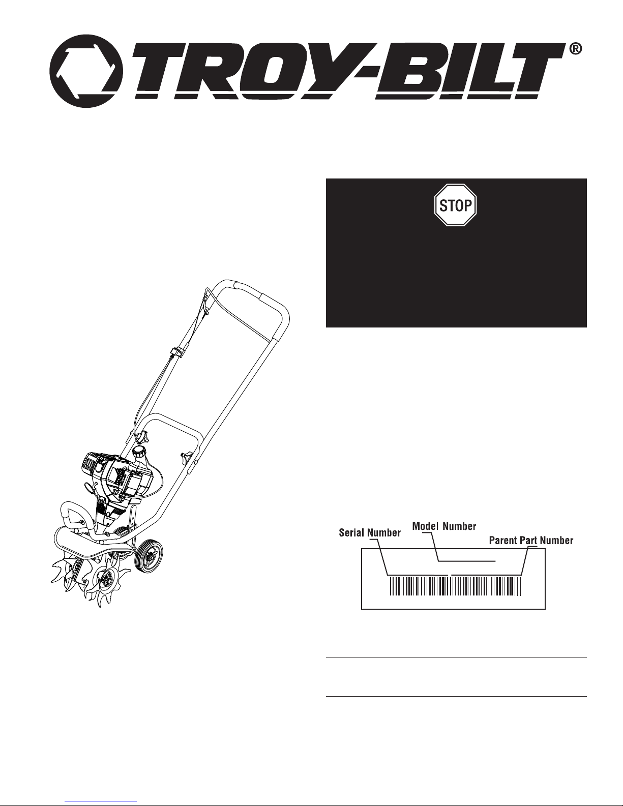
S/N : ITEM :
MODEL :
Before beginning, locate the unit’s model plate. It lists the model
and serial numbers of your unit. Refer to the sample plate below
and copy the information for future reference.

2
READ ALL INSTRUCTIONS BEFORE OPERATING
• Read the instructions carefully. Be familiar with the controls
and proper use of the unit.
• Do not operate this unit when tired, ill, or under the influence
of alcohol, drugs, or medication.
• Children and teens under the age of 15 must not use the unit,
except for teens guided by an adult.
• All guards and safety attachments must be installed properly
before operating the unit.
• Inspect the unit before use. Replace damaged parts. Check
for fuel leaks. Make sure all fasteners are in place and secure.
Replace parts that are cracked, chipped, or damaged in any
way. Do not operate the unit with loose or damaged parts.
• Carefully inspect the area before starting the unit. Remove all
debris and hard or sharp objects such as glass, wire, etc.
• Be aware of the risk of injury to the head, hands and feet.
• Clear the area of children, bystanders, and pets. At a
minimum, keep all children, bystanders, and pets outside a 50
feet (15 m) radius; there still may be a risk to bystanders from
thrown objects. Bystanders should be encouraged to wear
eye protection. If you are approached, stop the unit
immediately.
• Squeeze the throttle control and check that it returns auto-
matically to the idle position. Make all adjustments or repairs
before using unit.
SAFETY WARNINGS FOR GAS UNITS
• Store fuel only in containers specifically designed and
approved for the storage of such materials.
• Avoid creating a source of ignition for spilled fuel. Do not start
the engine until fuel vapors dissipate.
• Always stop the engine and allow it to cool before filling the
fuel tank. Never remove the cap of the fuel tank, or add fuel,
when the engine is hot. Never operate the unit without the fuel
cap securely in place. Loosen the fuel tank cap slowly to
relieve any pressure in the tank.
• Add fuel in a clean, well-ventilated outdoor area where there
are no sparks or flames. Slowly remove the fuel cap only after
stopping engine. Do not smoke while fueling or mixing fuel.
Wipe up any spilled fuel from the unit immediately. Always
wipe unit dry before using.
• Move the unit at least 30 feet (9.1 m) from the fueling source
and site before starting the engine. Do not smoke or allow
sparks and open flames near the area while adding fuel or
operating the unit.
WHILE OPERATING
• Never start or run the unit inside a closed room or building.
Breathing exhaust fumes can kill. Operate this unit only in a
well ventilated outdoor area.
• Wear safety glasses or goggles that meet ANSI Z87.1–1989
standards and are marked as such. Wear ear/hearing protection
when operating this unit. Wear a face or dust mask if the
operation is dusty.
• Wear heavy, long pants, boots, gloves and a long-sleeved shirt.
Do not wear loose clothing, jewelry, short pants, sandals or go
barefoot. Secure hair above shoulder level.
• This unit has a clutch. The tines remain stationary when the
engine is idling. If they do not, have the unit adjusted by an
authorized service technician.
• Be sure the tines are not in contact with anything before
starting the unit.
• Use the unit only in daylight or good artificial light.
• Avoid accidental starting. Be in the starting position whenever
pulling the starter rope. The operator and unit must be in a
stable position while starting. See Starting/Stopping
Instructions.
• IMPORTANT SAFETY INSTRUCTIONS •
RULES FOR SAFE OPERATION
Read the Operator’s Manual and follow all warnings and safety instructions. Failure to do so can result in serious injury to the
operator and/or bystanders.
FOR QUESTIONS, CALL 1-800-828-5500 IN U.S. OR 1-800-668-1238 in CANADA
The purpose of safety symbols is to attract your attention to possible dangers. The safety symbols, and their explanations, deserve your
careful attention and understanding. The safety warnings do not by themselves eliminate any danger. The instructions or warnings they
give are not substitutes for proper accident prevention measures.
NOTE: Advises you of information or instructions vital to the
operation or maintenance of the equipment.
SAFETY ALERT: Indicates danger, warning or
caution. Attention is required in order to avoid
serious personal injury. May be used in conjunction
with other symbols or pictographs.
DANGER: Failure to obey a safety warning will
result in serious injury to yourself or to others.
Always follow the safety precautions to reduce the
risk of fire, electric shock and personal injury.
WARNING: Failure to obey a safety warning can
result in injury to yourself and others. Always follow
the safety precautions to reduce the risk of fire,
electric shock and personal injury.
CAUTION: Failure to obey a safety warning may
result in property damage or personal injury to
yourself or to others. Always follow the safety
precautions to reduce the risk of fire, electric shock
and personal injury.
SYMBOL MEANING
SPARK ARRESTOR NOTE
NOTE: For users on U.S. Forest Land and in the states of
California, Maine, Oregon and Washington. All U.S. Forest
Land and the state of California (Public Resources Codes 4442
and 4443), Oregon and Washington require, by law that certain
internal combustion engines operated on forest brush and/or
grass-covered areas be equipped with a spark arrestor,
maintained in effective working order, or the engine be
constructed, equipped and maintained for the prevention of fire.
Check with your state or local authorities for regulations
pertaining to these requirements. Failure to follow these
requirements could subject you to liability or a fine. This unit is
factory equipped with a spark arrestor. If it requires
replacement, ask your LOCAL SERVICE DEALER to install the
Accessory Part #753-05297 Muffler Assembly.
CALIFORNIA PROPOSITION 65 WARNING
WARNING
THE ENGINE EXHAUST FROM THIS PRODUCT CONTAINS
CHEMICALS KNOWN TO THE STATE OF CALIFORNIA TO
CAUSE CANCER, BIRTH DEFECTS OR OTHER
REPRODUCTIVE HARM.
WARNING: When using the unit, you must follow
the safety rules. Please read these instructions
before operating the unit in order to ensure the
safety of the operator and any bystanders. Please
keep these instructions for later use.
WARNING: Gasoline is highly flammable, and its
vapors can explode if ignited. Take the following
precautions:

3
RULES FOR SAFE OPERATION
• SAFETY AND INTERNATIONAL SYMBOLS •
This operator's manual describes safety and international symbols and pictographs that may appear on this product. Read the operator's
manual for complete safety, assembly, operating and maintenance and repair information.
• Use the right tool. Only use this tool for the purpose intended.
• Use extreme caution when reversing or pulling the unit towards
you.
• Do not overreach. Always keep proper footing and balance.
Take extra care when working on steep slopes or inclines.
• Always hold the unit with both hands when operating. Keep a
firm grip on the grips.
• Keep hands, face, and feet at a distance from all moving parts.
Do not touch or try to stop the tines when they are rotating.
• Do not touch the engine or muffler. These parts get extremely
hot from operation, even after the unit is turned off.
• Do not operate the engine faster than the speed needed to
cultivate. Do not run the engine at high speed when you are
not cultivating.
• Always stop the engine when cultivating is delayed or when
walking from one cultivating location to another.
• If you strike or become entangled with a foreign object, stop
the engine immediately and check for damage. Do not
operate before repairing damage. Do not operate the unit
with loose or damaged parts.
• Stop the unit, switch the engine to off, and disconnect the
spark plug for maintenance or repair.
• Use only original equipment manufacturer replacement parts
and accessories for this unit. These are available from your
authorized service dealer. Use of any unauthorized parts or
accessories could lead to serious injury to the user, or
damage to the unit, and void your warranty.
• Keep unit clean of vegetation and other materials. They may
become lodged between the tines and guard.
• To reduce fire hazard, replace faulty muffler and spark
arrestor, keep the engine and muffler free from grass, leaves,
excessive grease or carbon build up.
AFTER USE
• Clean tines with a household cleaner to remove any gum
buildup. Oil the tines with machine oil to prevent rust.
OTHER SAFETY WARNINGS
• Never store a fueled unit inside a building where fumes may
reach an open flame or spark.
• Allow the engine to cool before storing or transporting. Be sure
to secure the unit while transporting.
• Store the unit in a dry area, locked up or up high to prevent
unauthorized use or damage, out of the reach of children.
• Never douse or squirt the unit with water or any other liquid.
Keep handles dry, clean and free from debris. Clean after each
use, see Cleaning and Storage instructions.
• Keep these instructions. Refer to them often and use them to
instruct other users. If you loan someone this unit, also loan
them these instructions.
SAVE THESE INSTRUCTIONS
• READ OPERATOR'S MANUAL
WARNING: Read the operator’s manual(s) and
follow all warnings and safety instructions. Failure to
do so can result in serious injury to the operator
and/or bystanders.
• KEEP BYSTANDERS AWAY
WARNING: Keep all bystanders, especially
children and pets, at least 50 feet (15 m) from the
operating area.
SYMBOL MEANING
• THROWN OBJECTS AND ROTATING CUTTER
CAN CAUSE SEVERE INJURY
WARNING: Do not operate without the cutting
attachment shield in place. Keep away from the
rotating cutting attachment.
• SAFETY ALERT SYMBOL
Indicates danger, warning or caution. May be used
in conjunction with other symbols or pictographs.
SYMBOL MEANING
• WEAR EYE AND HEARING PROTECTION
WARNING: Thrown objects and loud noise
can cause severe eye injury and hearing loss.
Wear eye protection meeting ANSI Z87.1–1989
standards and ear protection when operating this
unit. Use a full face shield when needed.
• OIL
Refer to operator’s manual for the proper type of oil.
• UNLEADED FUEL
Always use clean, fresh unleaded fuel.
• ON/OFF STOP CONTROL
OFF or STOP
• ON/OFF STOP CONTROL
ON / START / RUN
• HOT SURFACE WARNING
Do not touch a hot surface. You may get burned.
These parts get extremely hot from operation. They
remain hot for a short time after the unit is turned off.
• CHOKE CONTROL
1. • FULL choke position
2. • PARTIAL choke position
3. • RUN choke position
• GARDEN CULTIVATORS – ROTATING TINES
CAN CAUSE SEVERE INJURY
WARNING: Stop the engine and allow the tines
to stop before installing or removing tines, or
before cleaning or performing any maintenance.
Keep hands and feet away from rotating tines.
4
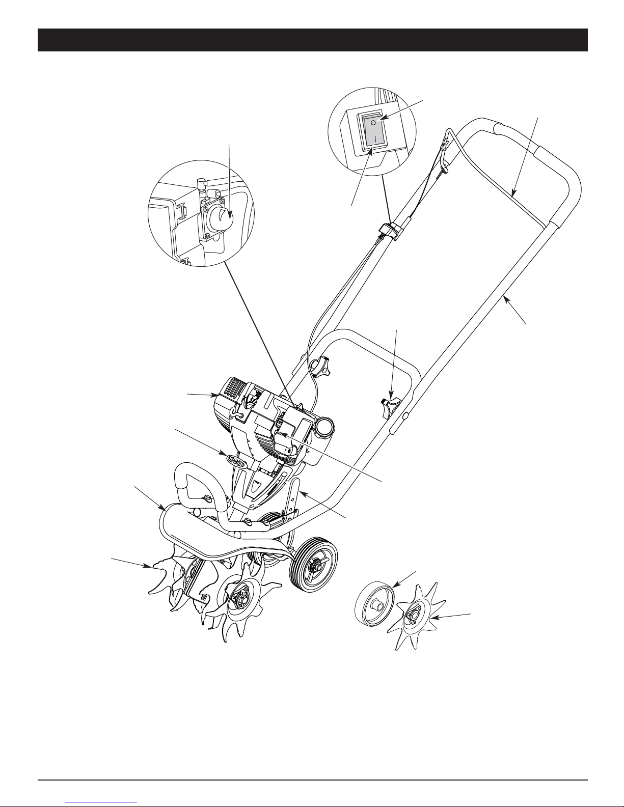
KNOW YOUR UNIT
Starter Rope Grip
Primer Bulb
Wheel Support
Bracket
Handlebar
Knob
Tine Guard
Cultivator
Tines
Choke
Control
Muffler
STOP/OFF (O)
START/ON (I)
Throttle
Control
Handlebar
APPLICATIONS
• Cultivating sod and light to medium soil
• Cultivating in garden areas, around trees, etc.
• Edging
Edger Wheel
Edger Blade

5
NOTE: Before setting up your cultivator / edger, disconnect
the spark plug wire from the spark plug.
POSITIONING THE HANDLEBARS
1. Loosen the two knobs on the inside of the handlebars (Fig. 1).
2. With the unit upright, swing the handlebars up into the
operating position (Fig. 2).
NOTE: Take care not to pinch the throttle cable or switch
wires when positioning the handlebar.
3. Tighten the knobs to secure the handlebars in place.
NOTE: Do not over-tighten the knobs.
4. Reconnect the spark plug wire to the spark plug.
ADJUSTING TINE DEPTH
To adjust the wheel support bracket proceed as follows:
1. Stop engine and disconnect spark plug to avoid accidental
starting.
2. Remove cotter pin from the clevis pin and slide clevis pin
out of tailpiece bracket (Fig. 3).
3. Slide the wheel support bracket up or down in the
tailpiece, aligning the holes to the desire height.
4. Place the clevis pin through the hole and secure with cotter
pin.
ASSEMBLY INSTRUCTIONS
Handlebar
Knob
Handlebars
Washer Hole
Bolt
Fig. 1
Fig. 2
Clevis Pin
Cotter Pin
Wheel
Support
Bracket
Tailpiece Bracket
Fig. 3
ATTACHING THE EDGER WHEEL AND BLADE
To convert the cultivator to an edger proceed as follows:
1. Push the On/Off switch to Off (O) position to stop engine and
tines and disconnect spark plug to avoid accidental starting.
NOTE: It may be necessary to lay the cultivator / edger back in
a horizontal position on a flat level surface with the
upper handle touching the ground.
2. Remove the click pin from each end of the tine shaft and
slide the tines off the shaft.
3. Slide the edger wheel, with the hub facing inward, onto the
right side of the tine shaft and secure with the click pin in
the inside hole (Fig. 4).
Fig. 4
Edger Guide
Line
Click Pin
Hub
Edger Blade
Edger Wheel
Tine Shaft
4. Slide the edger blade with the hub facing out onto the left
side of tine shaft and secure with the click pin in the inside
hole (Fig. 4).
5. The edger guide line indicates where cutting will occur.
Guide the unit along a flowerbed, sidewalk, or driveway so
the edger guide line is above the desired line of cut.

6
RECOMMENDED GASOLINE TYPE
Old gas is the primary reason for improper unit performance.
Be sure to use fresh, clean, unleaded gasoline.
NOTE: This is a four cycle engine. In order to avoid damage to
the unit, do not mix oil with gasoline.
Definition of Blended Fuels
Today's fuels are often a blend of gasoline and oxygenates such
as ethanol, methanol or MTBE (ether). Alcohol-blended fuel
absorbs water. As little as 1% water in the fuel can make fuel
form acids when stored. When using alcohol-blended fuel, use
fresh fuel that is less than 60 days old.
Using Blended Fuels
If you choose to use a blended fuel, or if its use is unavoidable,
follow recommended precautions:
• Always use fresh unleaded gasoline
• Use Sta-Bil® or an equivalent
• Drain tank and run the engine dry before storing unit
Using Fuel Additives
The use of fuel additives, such as Sta-Bil® or an equivalent, will
inhibit corrosion and minimize the formation of gum deposits.
Using a fuel additive can keep fuel from forming harmful deposits
in the carburetor for up to six (6) months. Add 0.8 oz. (23 ml.) of
fuel additive per gallon of fuel to an approved gas container
according to the instructions on the container. NEVER add fuel
additives directly to the unit's gas tank.
FUELING THE UNIT
1. Remove fuel cap. Remove the tag from the fuel tank neck.
NOTE: Fill or add gas to the tank only when the cultivator is in
a horizontal position (Fig. 9).
2. Place spout of gas container into the fill hole on the gas
tank and fill tank.
NOTE: Do not overfill tank.
3. Wipe up any gasoline that may have spilled.
4. Reinstall the gas cap.
5. Move the unit at least 30 ft. (9.1 m) from the fueling source
and site before starting the engine.
NOTE: Dispose of the old gasoline in accordance to Federal,
State and Local regulations.
Fig. 9
Gas Cap
OIL AND GAS INFORMATION
3. Remove the oil plug / dipstick from the crankcase (Fig. 7).
4. Pour the entire bottle of oil into the oil fill hole (Fig. 8).
NOTE: Never add oil to the gas or gas tank.
5. Wipe up any oil that may have spilled and reinstall the oil fill
plug / dipstick.
The importance of checking and maintaining the proper oil level
in the crankcase cannot be overemphasized. Check oil before
each use and change as specified in the Maintenance Schedule.
Fig. 7
Oil Fill Plug/
Dipstick
Oil Fill Hole
O-Ring
Fig. 8
Oil Fill
WARNING: Remove gas cap slowly to avoid
injury from fuel spray. Never operate the unit without
the fuel cap securely in place.
WARNING: Add fuel in a clean, well ventilated
outdoor area. Wipe up any spilled gas immediately.
Avoid creating a source of ignition for spilt fuel. Do
not start the engine until fuel vapors dissipate.
RECOMMENDED OIL TYPE
Using the proper type and weight of oil in the crankcase is
extremely important. Check the oil before each use and
change the oil regularly. Using incorrect or dirty oil can cause
premature engine wear and failure.
Use a high-quality SAE 30 weight oil of API (American
Petroleum Institute) service class SF, SG, SH.
ADDING OIL TO CRANKCASE: INITIAL USE
NOTE: This unit is shipped without oil in
the crankcase. In order to avoid
damage to the unit, put oil in the
crankcase before attempting to
start unit.
Your unit is supplied with one 3.04 fluid
oz. (90 ml) bottle of SAE 30 SF, SG, SH
oil (Fig. 5).
NOTE: Save the bottle to measure the
correct amount for future oil
changes. See Changing the Oil.
NOTE:
Your new 4-Cycle cultivator is
shipped for operation in
conditions above 40°F (4°C). For cold weather
operation, where temperatures fall below 40°F (4°C),
use a high-quality SAE 10W30 weight oil of API
(American Petroleum Institute) service class SF, SG, SH.
1. Unscrew the oil bottle top and remove the paper seal
covering the opening. Replace the top and cut the tip off
the funnel spout (Fig. 5).
2. Place the unit on a flat level surface with the cultivator in a
horizontal position (Fig. 6).
Fig. 5
Fig. 6
Oil Fill
Plug/Dipstick
CAUTION: OVERFILLING OIL CRANKCASE MAY
CAUSE PRODUCT DAMAGE. Check and maintain the
proper oil level in the crank case; it is important and
cannot be overemphasized. Check the oil before each
use and change it as needed. See Changing the Oil.

7
1. Check the oil level in the crankcase. Refer to Checking the
Oil Level.
2. Fill the fuel tank with fresh, clean unleaded gasoline. Refer
to Fueling the Unit.
3. Put the On/Off Stop Control in the ON [I] position (Fig. 10).
4. Place the choke lever in Position 1(Fig. 11).
5. Fully press and release the primer bulb 10 times, slowly.
Some amount of fuel should be visible in the primer bulb
and fuel lines (Fig. 11). If you can’t see fuel in the bulb,
press and release the bulb as many times as it takes before
you can see fuel in it.
6. Hold the throttle and handlebar with one hand and grab the
starter rope with your other hand. Use your foot to hold
down the cultivator (Fig. 12).
NOTE: Tilt the unit back slightly to bring the tines off the
ground when starting.
7. While squeezing the throttle control, pull the starter rope
with a smooth and steady pull. Repeat this 5 times.
8. Move the choke lever to Position 2.
9. While squeezing the throttle control, pull the starter rope in
the same manner as explained in Step 7. Pull 1 to 4 times
to start the engine.
10. Keep the throttle squeezed and allow the engine to warm
up for 30 to 60 seconds.
11. Place the choke lever in Position 3. Release the throttle
control to the idle position and begin operation.
IF... The engine does not start, repeat Steps 4–11.
IF... The engine fails to start after a few attempts, place the
choke lever in Position 3and squeeze the throttle control.
Pull the starter rope 3 to 8 times. The engine should start.
If not, continue pulling starter rope until the engine starts.
IF WARM... If the engine is already warm, make sure the
On/Off Stop control is in the ON position and start the
unit with the choke lever in Position 2. After the unit
starts, move the choke lever to Position 3.
STOPPING INSTRUCTIONS
1. Release your hand from the throttle control. Allow the
engine to cool down by idling.
2. Put the On/Off Stop Control in the OFF (O) position (Fig. 10).
STARTING INSTRUCTIONS
Primer Bulb
Fig. 10
Throttle
Control
ON (I)
OFF (O)
STARTING / STOPPING INSTRUCTIONS
Fig. 12
Starter
Rope
Throttle
Control
12 3
Choke Lever
Position 3
Position 1
Position 2
Fig. 11
WARNING: Operate this unit only in a well-
ventilated outdoor area. Carbon monoxide exhaust
fumes can be lethal in a confined area.
WARNING: Avoid accidental starting. Make sure
you are in the starting position when pulling the starter
rope (Fig. 12). To avoid serious injury, the operator and
unit must be in a stable position while starting.

8
Click Pin
“A” Tine
Fig. 14
TINE REMOVAL AND REPLACEMENT
All 4 tines should be replaced at the same time because they will
wear evenly through normal use. Work on one side at a time.
1. Put the On/Off Stop Control in the STOP (O) position
and disconnect the spark plug wire.
NOTE: It may be necessary to lay the cultivator back in a
horizontal position on a flat level surface with the
upper handle touching the ground.
2. Remove the click pin from each end of the tine shaft. Slide
the tines off of the shaft (Fig. 14).
“B” Tine
Hubs
MAINTENANCE SCHEDULE
Perform these required maintenance procedures at the
frequency stated in the table. These procedures should also be
a part of any seasonal tune-up.
NOTE: Some maintenance procedures may require special
tools or skills. If you are unsure about these procedures,
take your unit to a qualified service dealer.
NOTE: Maintenance, replacement, or repair of the emission
control devices and system may be performed by a
qualified service dealer.
3. Clean and oil the shaft.
4. Slide on the new tines with the hubs facing out. The four
tines are marked with the letters “A” or “B.”
5. Place one “A” tine and one “B” tine onto the shaft.
6. Secure the new tines to the shaft with click pins. It may be
necessary to wash the dirt off the tines and shaft for ease
of removal.
FREQUENCY MAINTENANCE REQUIRED SEE
Before using Fill fuel tank with fresh fuel
Check oil while the engine is cold p 6
p 9
Every 10 hrs Clean and re-oil air filter p 9
1st service at 10 hrs Change oil p 9
Every 25 hrs
thereafter Change oil
Clean spark arrestor p 9
p 12
Every 25 hrs
Check spark plug condition and gap
p 12
WARNING: To prevent serious injury, never
perform maintenance or repairs with unit running.
Always service and repair a cool unit. Disconnect the
spark plug wire to ensure that the unit cannot start.
WARNING: To prevent serious personal injury,
always wear heavy gloves when handling the tines.
TRANSPORTING THE UNIT
1. Stop the engine.
2. Tilt the unit back until the tines clear the ground.
3. Push or pull the unit to the next location to be
cultivated.
OPERATING TIPS
1. Move the cultivator to the work area prior to starting the
engine. Transport the cultivator by pushing or pulling it
along on its wheels.
2. Start the unit by following the Starting Instructions.
3. With the engine running and the tines off the ground,
depress the throttle control to increase the engine speed.
4. While holding the upper handle with both hands, slowly
lower the cultivator until the tines make contact with the
ground (Fig. 13).
5. As cultivating action begins, tilt the cultivator up slightly
using the handle so that the tines can penetrate the ground.
6. Once the ground has been broken, continue at a moderate
pace until you are familiar with the controls and the
handling of the cultivator.
7. If the tines are digging too deep or not deep enough, adjust
the wheel bracket as described in Adjusting Tine Depth.
OPERATING INSTRUCTIONS
Fig. 13
MAINTENANCE AND REPAIR INSTRUCTIONS
WARNING: To prevent serious personal injury,
never pick-up or carry the unit while the engine is
running.
WARNING: To prevent serious personal injury,
use extreme caution when reversing or pulling the
unit towards you.
WARNING: To prevent serious personal injury,
always stop the engine when operation is delayed or
when transporting the unit from one location to
another.
WARNING: Dress properly to reduce the risk of
injury when operating this unit. Do not wear loose
clothing or jewelry. Wear eye and ear/hearing
protection. Wear heavy long pants, boots and gloves.
Do not wear short pants, sandals or operate barefoot.

9
CHECKING THE OIL LEVEL
The importance of checking and maintaining the proper oil level in the
crankcase cannot be overemphasized. Check oil before each use:
1. Stop the engine and allow oil to drain into the crankcase.
2. Place the unit in a horizontal position to get a proper oil
level reading (Fig. 9).
3. Keep dirt, grass clippings and other debris out of the
engine. Clean the area around the oil fill plug/dipstick
before removing it.
4. Remove the oil fill plug/dipstick and wipe off oil. Reinsert it
all the way back in.
5. Remove the oil fill plug/dipstick and check the oil level. Oil
should be up to the top of the dipstick (Fig. 15).
6. If the level is low, add a small amount of oil to the oil fill
hole and recheck (Fig. 16). Repeat this procedure until the
oil level reaches the top of the dipstick.
NOTE: Do not overfill the unit.
Top of Dipstick
O-Ring
Oil Fill Plug/Dipstick
Fig. 15
NOTE: Make sure the O-ring is in place on the oil fill plug/dipstick
when checking and changing the oil (Fig. 16).
Full
Add 1.4-1.5 Oz.
(41-44 ml)
MAINTENANCE AND REPAIR INSTRUCTIONS
CAUTION: To prevent extensive engine wear and
damage to the unit, always maintain the proper oil
level in the crankcase. Never operate the unit with
the oil level below the bottom of the dipstick.
CHANGING THE OIL
For a new engine, change the oil after the first 10 hours of
operation. Change the oil while the engine is still warm. The oil
will flow freely and carry away more impurities.
1. Unplug spark plug wire to prevent accidental starting.
2. Remove the oil fill plug/dipstick.
3. Pour the oil out of the oil fill hole and into a container by
tipping the unit to a vertical position (Fig. 17). Allow ample
time for complete drainage.
WARNING: Wear gloves to prevent injury when
handling the unit.
Fig. 17
4. Wipe up any oil residue on the unit and clean up any oil
that may have spilled. Dispose of the oil according to
Federal, State and local regulations.
5. Refill the crankcase with 3.04 fluid ounce (90 ml) of SAE 30
SF, SG, SH oil.
NOTE: Use the bottle and spout saved from initial use to
measure the correct amount of oil. Pour fresh fuel into
the bottle and fill it to the top of the label (Fig. 18). The
top of the label on the bottle measures approximately
3.04 ounces (90 ml). Check the level with the dipstick.
If the level is low, add a small amount of oil and
recheck. Do not overfill (Fig. 18).
Fill Level
Fig. 18
Fig. 16
Oil Fill Plug/
Dipstick
Oil Fill Hole
O-Ring
6. Replace the oil fill plug/dipstick.
7. Reconnect the spark plug wire.

10
4. Apply enough clean SAE 30 motor oil to lightly coat the filter
(Fig. 21).
5. Squeeze the filter to spread and remove excess oil (Fig. 21).
6. Replace the filter (Fig. 19).
NOTE: If the unit is operated without the air filter, you will
VOID the warranty.
7. Reinstall the air filter cover. Position the hooks on the right
side of the air filter cover into the slots at the right side of
the air filter housing (Fig. 19).
8. Swing the cover to the left until the air filter screw contacts
the air filter housing (Fig. 19).
9. Twist the air filter screw clockwise into the screw hole until it
stops. DO NOT OVERTIGHTEN.
CARBURETOR ADJUSTMENT
The idle speed of the engine is adjustable. An idle adjustment screw
is reached though a hole in the top of the engine cover (Fig. 22).
NOTE: Careless adjustments can seriously damage your unit.
For carburetor adjustments, take your unit to a qualified
service dealer.
Adjust Idle Speed Screw
If, after checking the fuel and cleaning the air filter, the engine
still will not idle, adjust the idle speed screw as follows:
1. Start the engine and let it run at a high idle for a minute to
warm up. Refer to Starting/Stopping Instructions.
NOTE: Ensure the tines are not in contact with the ground
when adjusting the idle.
2. Release the throttle trigger and let the engine idle. If the
engine stops, insert a small phillips or flat blade screwdriver
into the hole in the air filter/muffler cover (Fig. 21). Turn the
idle speed screw in, clockwise, 1/8 of a turn at a time (as
needed) until the engine idles smoothly.
NOTE: The tines should not rotate when the engine idles.
3. If the tines rotate when the engine idles, turn the idle speed
screw counterclockwise 1/8 of a turn at a time (as needed),
to reduce idle speed.
Checking the fuel, cleaning the air filter, and adjusting the idle
speed should solve most engine problems. If not and all of the
following are true:
• the engine will not idle
• the engine hesitates or stalls on acceleration
• there is a loss of engine power
Have the carburetor adjusted by a qualified service dealer.
Fig. 21
12 3
Idle
Adjustment
Screw
Fig. 22
Check Fuel
Old fuel is usually the reason for improper unit performance. Drain
and refill the tank with fresh fuel prior to making any adjustments.
Refer to Oil and Fuel Information.
Clean Air Filter
The condition of the air filter is important to the operation of the unit.
A dirty air filter will restrict air flow. This is often mistaken for an out
of adjustment carburetor. Check the condition of the air filter before
adjusting the idle speed screw. Refer to Air Filter Maintenance.
MAINTENANCE AND REPAIR INSTRUCTIONS
Air Filter
Air Filter
Screen
Hooks
Choke Lever
Air Filter Cover
Air Filter
Housing
Air Filter
Screw
Fig. 19
Air Filter
Housing
3. Wash the filter in detergent and water (Fig. 20). Rinse the
filter thoroughly and allow it to dry.
Fig. 20
WARNING: This unit needs to run during idle speed
adjustment. Wear protective clothing and observe all
safety instructions to prevent serious personal injury.
AIR FILTER MAINTENANCE
Cleaning the Air Filter
Clean and re-oil the air filter every 10 hours of operation. It is an
important item to maintain. Failure to maintain your air filter
properly can result in poor performance or can cause permanent
damage to your engine.
1. Open the air filter cover. Push the tab on the left side of the cover
in, swing the air filter cover out and off the air filter housing (Fig. 19).
2. Remove the air filter and the screen that sits behind it (Fig. 19).
WARNING: To avoid serious personal injury,
always turn the unit off and allow it to cool before
you clean or service it.

11
T-20
Screws
Engine Cover
Fig. 23
Muffler
ROCKER ARM CLEARANCE
This requires disassembly of the engine. If you feel unsure or
unqualified to perform this, take the unit to a qualified service
dealer.
NOTE: Inspect the valve to rocker arm clearance with a feeler
gauge after the first 10 hours of operation and then
every 25 hours of operation thereafter.
• The engine must be cold when checking or adjusting the
valve clearance.
• This task should be performed inside, in a clean, dust free area.
1. Remove the five (5) screws with a Flat-head or T-20 Torx
screwdriver (Fig. 23).
MAINTENANCE AND REPAIR INSTRUCTIONS
Rocker Arm Cover
Fig. 25
Spark Plug Hole
Gasket
T-25 Screw
Fig. 24
8. Slide the feeler gauge between the rocker arm and the
valve return spring. Measure the clearance between the
valve stem and rocker arm. Measure both the intake and
exhaust valves (Fig. 26 & 27).
2. Remove the screw behind the engine cover with a Flat-
head or T-25 Torx screwdriver (Fig. 24).
Adjusting Nuts
Feeler Gauge
Rocker Arms
Fig. 26
INTAKE
EXHAUST
3. Disconnect the spark plug wire.
4. Clean dirt from around the spark plug. Remove the spark
plug from the cylinder head by turning it counterclockwise
with a 5/8” socket.
5. Remove the engine cover.
NOTE: To ease engine cover removal, pull the starter rope out
a little to give some slack.
6. Clean dirt from around the rocker arm cover. Remove the
screw holding the rocker arm cover with a large flat blade
screwdriver or Torx T-25 bit (Fig. 25). Remove the rocker
arm cover and gasket.
7. Pull the starter rope slowly to bring the piston to the top of
its travel, (known as top dead center). Check that:
• The piston is at the top of its travel while looking in the spark
plug hole (Fig. 25).
• Both rocker arms move freely, and both valves are closed
If these statements are not true, repeat this step.
Fig. 27
Feeler Gauge
Adjusting Nut
Rocker Arm
0.003–0.006 in.
(0.076–0.152 mm)
Exhaust Valve
Stem
The recommended clearance for both intake and exhaust is
0.003 – 0.006 in. (0.076 – 0.152 mm). Use a standard automotive
0.005 in. (0.127 mm) feeler gauge. The feeler gauge should slide
between the rocker arm and valve stem with a slight amount of
resistance, without binding. See Figure 26 and 27.
9. If the clearance is not within specification:
a. Turn the adjusting nut using a 5/16 inch (8 mm) wrench or
nut driver (Fig. 27).
• To increase clearance, turn the adjusting nut
counterclockwise.
• To decrease clearance, turn the adjusting nut clockwise.
b. Recheck both clearances, and adjust as necessary.
Intake Valve
Stem
12
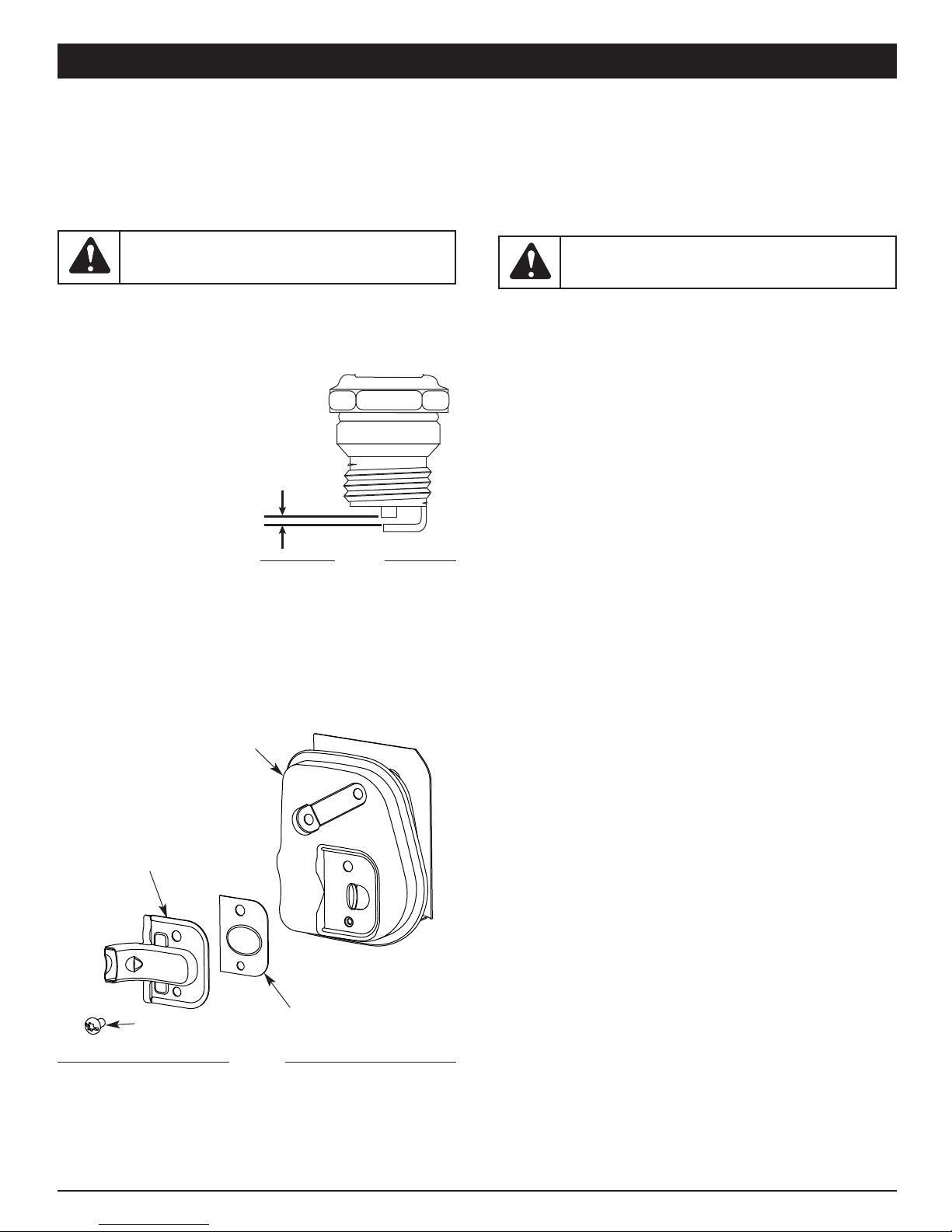
REPLACING THE SPARK PLUG
Use a replacement part #753-05784 or Champion ref. #RDZ4H.
The correct spark gap is 0.025 in. (0.635 mm). Remove the plug
after every 25 hours of operation and check its condition.
1. Stop the engine and allow it to cool. Grasp the plug wire
firmly and pull the cap from the spark plug.
2. Clean dirt from around the
spark plug. Remove the
spark plug from the
cylinder head by turning it
counterclockwise with a
5/8” socket.
3. Replace cracked, fouled or
dirty spark plug. Set the air
gap at 0.025 in. (0.635 mm)
using a feeler gauge (Fig.
28).
4. Install a correctly-gapped
spark plug in the cylinder
head. Turn the 5/8 in.
socket clockwise until snug.
If using a torque wrench torque to:
110-120 in.•lb. (12.3-13.5 N•m)
Do not over tighten.
Fig. 29
SPARK ARRESTOR MAINTENANCE
1. Remove the muffler cover. See Rocker Arm Clearance.
2. With a flat blade screwdriver or Torx T-20 bit, remove the screw
attaching the spark arrestor cover to the muffler (Fig. 29).
3. Remove the spark arrestor cover.
4. Remove the spark arrestor screen from the spark arrestor
cover.
5. Clean the spark arrestor screen with a wire brush or
replace it.
6. Reinstall the spark arrestor screen, spark arrestor cover
and screw.
CLEANING THE UNIT
• Use a small brush to clean off the outside of the unit and to
keep the air vents free of obstructions.
• Do not use strong detergents or petroleum based cleaners,
such as kerosene. Some household cleaners contain aromatic
oils such as pine and lemon that can damage the plastic
housings or handles. Wipe off any moisture with a soft cloth.
STORAGE
• Never store the unit with fuel in the tank where fumes may
reach an open flame or spark.
• Allow the engine to cool before storing.
• Store the unit in a locked up area to prevent
unauthorized use or damage.
• Store the unit in a dry, well-ventilated area. Do not store next
to corrosive material like fertilizer.
• Store the unit out of the reach of children.
LONG-TERM STORAGE
If the unit will be stored for an extended time:
1. Carefully drain all gasoline from the fuel tank by removing
the fuel cap and tipping the motor housing over to allow
the fuel to drain into an approved gas container. Do not
use gas that has been stored for more than 60 days.
Dispose of the old gasoline in accordance with Federal,
State and Local regulations.
2. Start the engine and allow it to run until it stalls. This
ensures that all gasoline has been drained from the
carburetor.
3. Allow the engine to cool. Remove the spark plug and put 5
drops of high quality motor oil into the cylinder. Pull the
starter rope slowly to distribute the oil. Reinstall the spark
plug.
NOTE: Remove the spark plug and drain all of the oil from the
cylinder before attempting to start the unit after
storage.
4. Change the oil, referring to the Changing the Oil section.
Dispose of the old oil in accordance with Federal, State
and Local regulations.
5. Thoroughly clean the unit and inspect for any loose or
damaged parts. Repair or replace damaged parts and
tighten loose screws, nuts or bolts.
6. To take up less storage area, loosen the handlebar knobs
and fold the handlebar down. The unit is ready for storage.
TRANSPORTING
• Allow the engine to cool before transporting.
• Secure the unit while transporting.
• Drain the fuel tank before transporting.
• Tighten fuel cap before transporting.
MAINTENANCE AND REPAIR INSTRUCTIONS
10. Reinstall the rocker arm cover using a new gasket. Torque
the screw to 20–30 in•lb (2.2–3.4 N•m).
11. Reinstall the engine cover. Check alignment of the cover
before tightening the screws. Tighten screws.
12. Check the spark plug and reinstall. See Replacing the
Spark Plug.
13. Replace the spark plug wire.
WARNING: To avoid serious personal injury,
always turn the unit off and allow it to cool before
you clean or perform any maintenance on it.
WARNING: Do not sand blast, scrape or clean
electrodes. Grit in the engine could damage the
cylinder.
0.025 in.
(0.635 mm)
Fig. 28
Muffler
Spark Arrestor Screen
Spark Arrestor Cover
Screw

13
TROUBLESHOOTING
If further assistance is required, contact your authorized service dealer.
CAUSE ACTION
Air filter is plugged Replace or clean the air filter
Old gas Drain gas tank and add fresh fuel
Improper carburetor adjustment Adjust according to the Carburetor Adjustments section or take
to an authorized service dealer for an adjustment
CAUSE ACTION
On/Off control in the STOP position
Turn On/Off control to ON
Empty fuel tank Fill fuel tank with fuel
Primer bulb wasn't pressed enough Press primer bulb fully and slowly 10 times
Old gas Drain gas tank and add fresh fuel
Fouled spark plug Replace or clean the spark plug
Plugged spark arrestor Clean or replace spark arrestor
Engine is flooded Pull starter rope repeatedly with throttle control fully
engaged and with the choke lever in Position 3
CAUSE ACTION
Old gas Drain gas tank and add fresh fuel
Fouled spark plug Replace or clean the spark plug
Plugged spark arrestor Clean or replace spark arrestor
Low power Rocker arm clearance adjustment (see page 18)
Cultivator tines bound with dirt or grass Stop the unit, switch the On/Off Stop Control to STOP, clean
and remove any debris binding the tines
CAUSE ACTION
Old gas Drain gas tank and add fresh fuel
Dirty air filter Clean or replace the air filter
Plugged spark arrestor Clean or replace spark arrestor
Cultivator tines bound with dirt or grass Stop the unit, switch the On/Off Stop Control to STOP, clean
and remove any debris binding the tines
CAUSE ACTION
Oil fill plug/dipstick loose or missing o-ring Tighten oil fill plug/dipstick, replace o-ring
CAUSE ACTION
Spark plug gap is too small/close Adjust gap to 0.025”
ENGINE WILL NOT START
ENGINE WILL NOT IDLE
ENGINE WILL NOT ACCELERATE
ENGINE LACKS POWER OR STALLS WHEN CUTTING
SIGNS OF OIL AROUND OIL FILL PLUG / DIPSTICK
UNIT OCCASIONALLY HESITATES AT HIGH SPEEDS

* All specifications are based on the latest product information available at the time of printing. We reserve the right to make changes at
any time without notice.
Engine Type . . . . . . . . . . . . . . . . . . . . . . . . . . . . . . . . . . . . . . . . . . . . . . . . . . . . . . . . . . . . . . . . . . . . . . . . . . . . . . . . . Air-Cooled, 4-Cycle
Displacement . . . . . . . . . . . . . . . . . . . . . . . . . . . . . . . . . . . . . . . . . . . . . . . . . . . . . . . . . . . . . . . . . . . . . . . . . . . . . . . . 1.6 cu. in. (26.2 cc)
Idle Speed RPM . . . . . . . . . . . . . . . . . . . . . . . . . . . . . . . . . . . . . . . . . . . . . . . . . . . . . . . . . . . . . . . . . . . . . . . . . . . . . . . . 3,000-3,600 rpm
Operating RPM . . . . . . . . . . . . . . . . . . . . . . . . . . . . . . . . . . . . . . . . . . . . . . . . . . . . . . . . . . . . . . . . . . . . . . . . . . . . . . . . 7,200-8,800 rpm
Clutch Type . . . . . . . . . . . . . . . . . . . . . . . . . . . . . . . . . . . . . . . . . . . . . . . . . . . . . . . . . . . . . . . . . . . . . . . . . . . . . . . . . . . . . . . . . Centrifugal
Ignition Type . . . . . . . . . . . . . . . . . . . . . . . . . . . . . . . . . . . . . . . . . . . . . . . . . . . . . . . . . . . . . . . . . . . . . . . . . . . . . . . . . . . . . . . . . Electronic
On/Off Stop Control . . . . . . . . . . . . . . . . . . . . . . . . . . . . . . . . . . . . . . . . . . . . . . . . . . . . . . . . . . . . . . . . . . . . . . . . Positive On/Off Switch
Valve clearance (intake and exhaust) . . . . . . . . . . . . . . . . . . . . . . . . . . . . . . . . . . . . . . . . . . . . . . . . 0.003–0.006 in. (0.076–0.0152 mm)
Spark Plug Gap . . . . . . . . . . . . . . . . . . . . . . . . . . . . . . . . . . . . . . . . . . . . . . . . . . . . . . . . . . . . . . . . . . . . . . . . . . . . 0.025 inch (0.635 mm)
Lubrication . . . . . . . . . . . . . . . . . . . . . . . . . . . . . . . . . . . . . . . . . . . . . . . . . . . . . . . . . . . . . . . . . . . . . . . . . . . . . . . . . . . . . . . . . SAE 30 Oil
Crankcase Oil Capacity . . . . . . . . . . . . . . . . . . . . . . . . . . . . . . . . . . . . . . . . . . . . . . . . . . . . . . . . . . . . . . . . . . . . . . . . . . . . 3.04 oz (90 ml)
Fuel . . . . . . . . . . . . . . . . . . . . . . . . . . . . . . . . . . . . . . . . . . . . . . . . . . . . . . . . . . . . . . . . . . . . . . . . . . . . . . . . . . . . . . . . . . . . . . . Unleaded
Carburetor . . . . . . . . . . . . . . . . . . . . . . . . . . . . . . . . . . . . . . . . . . . . . . . . . . . . . . . . . . . . . . . . . . . . . . . . . . . . . . . Diaphragm, All-Position
Starter . . . . . . . . . . . . . . . . . . . . . . . . . . . . . . . . . . . . . . . . . . . . . . . . . . . . . . . . . . . . . . . . . . . . . . . . . . . . . . . . . . . . . . . . . . . Auto Rewind
Muffler . . . . . . . . . . . . . . . . . . . . . . . . . . . . . . . . . . . . . . . . . . . . . . . . . . . . . . . . . . . . . . . . . . . . . . . . . . . . . . . . . . . . . . Baffled with Guard
Throttle . . . . . . . . . . . . . . . . . . . . . . . . . . . . . . . . . . . . . . . . . . . . . . . . . . . . . . . . . . . . . . . . . . . . . . . . . . . . . . . . . . . . . . . . . Spring Return
Fuel Tank Capacity . . . . . . . . . . . . . . . . . . . . . . . . . . . . . . . . . . . . . . . . . . . . . . . . . . . . . . . . . . . . . . . . . . . . . . . . . . . . . . . . 18 oz (532 ml)
Cultivating Path Width (Maximum) . . . . . . . . . . . . . . . . . . . . . . . . . . . . . . . . . . . . . . . . . . . . . . . . . . . . . . . . . . . . . . . 9 inches (22.86 cm)
Cultivating Depth (Maximum) . . . . . . . . . . . . . . . . . . . . . . . . . . . . . . . . . . . . . . . . . . . . . . . . . . . . . . . . . . . . . . . . . . . 6 inches (15.24 cm)
Approximate Weight (no fuel) . . . . . . . . . . . . . . . . . . . . . . . . . . . . . . . . . . . . . . . . . . . . . . . . . . . . . . . . . . . . . . . . . . . . . . . 25 lb. (11.5 kg)
SPECIFICATIONS
CULTIVATOR*
ENGINE*
CALIFORNIA / EPA EMISSION CONTROL WARRANTY STATEMENT
Your Warranty Rights and Obligations
The California Air Resources Board, the Environmental Protection Agency, and Troy-Bilt LLC (Troy-Bilt) are pleased to explain the
emission control system warranty on your 2008 and later small off-road engine. In California and the 49 states, new small off-road
engines must be designed, built and equipped to meet the state’s stringent anti-smog standards. Troy-Bilt must warrant the emission
control system on your small off-road engine for the periods of time listed below provided there has been no abuse, neglect or
improper maintenance of your small off-road engine.
Your emission control system may include parts such as the carburetor or fuel-injection system, the ignition system, and catalytic
converter. Also included may be hoses, belts, connectors and other emission-related assemblies.
Where a warrantable condition exists, Troy-Bilt will repair your small off-road engine at no cost to you including diagnosis, parts and
labor.
The 2008 and later small off-road engines are warranted for two years. If any emission-related part on your engine is defective, the part
will be repaired or replaced by Troy-Bilt.
Owners Warranty Responsibilities
As the small off-road engine owner, you are responsible for the performance of the required maintenance listed in your operator’s
manual. Troy-Bilt recommends that you retain all receipts covering maintenance on your small off-road engine, but Troy-Bilt cannot
deny warranty solely for the lack of receipts or for your failure to ensure the performance of all scheduled maintenance.
• As the small off-road engine owner, you should however be aware that Troy-Bilt may deny you warranty coverage if your small off-
road engine or a part has failed due to abuse, neglect, improper maintenance or unapproved modifications.
• You are responsible for presenting your small off-road engine to a Troy-Bilt Authorized Service Center as soon as a problem exists.
The warranty repairs should be completed in a reasonable amount of time, not to exceed 30 days.
If you have any questions regarding your warranty rights and responsibilities, you should call 1-800-828-5500.
Manufacturer’s Warranty Coverage
• The warranty period begins on the date the engine or equipment is delivered to the retail purchaser.
• The manufacturer warrants to the initial owner and each subsequent purchaser, that the engine is free from defects in material and
workmanship which cause the failure of a warranted part for a period of two years.
• Repair or replacement of warranted part will be performed at no charge to the owner at an Authorized Troy-Bilt Service Center. For
the nearest location please contact Troy-Bilt at: 1-800-828-5500.
• Any warranted part which is not scheduled for replacement, as required maintenance or which is scheduled for only for regular
inspection to the effect of “Repair or Replace as Necessary” is warranted for the warranty period. Any warranted part which is
scheduled for replacement as required maintenance will be warranted for the period of time up to the first scheduled replacement
point for that part.
• The owner will not be charged for diagnostic labor which leads to the determination that a warranted part is defective, if the
diagnostic work is performed at an Authorized Troy-Bilt Service Center.
• The manufacturer is liable for damages to other engine components caused by the failure of a warranted part still under warranty.
• Failures caused by abuse, neglect or improper maintenance are not covered under warranty.
• The use of add-on or modified parts can be grounds for disallowing a warranty claim. The manufacturer is not liable to cover failures
14

of warranted parts caused by the use of add-on or modified parts.
• In order to file a claim, go to your nearest Authorized Troy-Bilt Service Center. Warranty services or repairs will be provided at all
Authorized Troy-Bilt Service Centers.
• Any manufacturer approved replacement part may be used in the performance of any warranty maintenance or repair of emission
related parts and will be provided without charge to the owner. Any replacement part that is equivalent in performance or durability
may be used in non-warranty maintenance or repair and will not reduce the warranty obligations of the manufacturer.
Emission Warranty Parts List:
The following components are included in the emission-related warranty of the engine: air filter, carburetor, primer, fuel lines, fuel pick
up/ fuel filter, ignition module, spark plug, and muffler. Valves and Cam are additionally included if your engine is a 4-Stroke Model.
CALIFORNIA EVAPORATIVE EMISSION CONTROL WARRANTY STATEMENT
Your Warranty Rights and Obligations
The California Air Resources Board and Troy-Bilt LLC (Troy-Bilt) is pleased to explain the evaporative emission control system’s
warranty on your 2008 model year and later small off-road (equipment type) engine. In California, new equipment that use small off-
engines must be designed, built, and equipped to meet the State’s stringent anti-smog standards Troy-Bilt must warrant the
evaporative emission control system on your small off-road Lawn & Garden engine for the period listed below provided there has been
no abuse, neglect or improper maintenance of your equipment.
Your evaporative emission control system may include parts such as: carburetors, fuel tanks, fuel lines, fuel caps, valves, canisters,
filters, vapor hoses, clamps, connectors, and other associated components. For engines less than or equal to 80 cc, only the fuel tank
is subject to the evaporative emission control warranty requirements of this section. The displacement of your small off road engine is
less than 80 cc.
Manufacturer’s Warranty Coverage
This evaporative emission control system is warranted for two years. If any evaporative emission-related part on your equipment is
defective, the part will be repaired or replaced by Troy-Bilt.
Owner’s Warranty Responsibilities
• As the small off-road Lawn & Garden engine owner, you are responsible for performance of the required maintenance listed in your
owner’s manual. Troy-Bilt recommends that you retain all receipts covering maintenance on your Lawn & Garden Engine but Troy-Bilt
cannot deny warranty solely for the lack of receipts.
• As the small off-road Lawn & Garden engine owner, you should however be aware that the Troy-Bilt may deny you warranty
coverage if your fuel tank has failed due to abuse, neglect, or improper maintenance or unapproved modifications.
• You are responsible for presenting your Lawn & Garden fuel tank to Troy-Bilt distribution center or service center as soon as the
problem exists. The warranty repairs should be completed in a reasonable amount of time, not to exceed 30 days. If you have a
question regarding your warranty coverage, you should contact Troy-Bilt at 1-800-828-5500.
Defects Warranty Requirements
(a) The warranty period begins on the date the engine or equipment is delivered to an ultimate purchaser.
(b) General Evaporative Emissions Warranty Coverage. The fuel tank must be warranted to the ultimate purchaser and any
subsequent owner that the evaporative emission control system when installed was:
(1) Designed, built, and equipped so as to conform with all applicable regulations; and
(2) Free from defects in materials and workmanship that causes the failure of a warranted part for a period of two years.
(c) The warranty on evaporative emissions-related parts will be interpreted as follows:
(1) Any warranted part that is not scheduled for replacement as required maintenance in the written instructions must be
warranted for the warranty period defined in subsection (b)(2). If any such part fails during the period of warranty coverage, it
must be repaired or replaced by Troy-Bilt. Any such part repaired or replaced under the warranty must be warranted for a
time not less than the remaining warranty period.
(2) Any warranted part that is scheduled only for regular inspection in the written instructions must be warranted for the warranty
period defined in subsection (b)(2). A statement in such written instructions to the effect of “repair or replace as necessary”
will not reduce the period of warranty coverage. Any such part repaired or replaced under warranty must be warranted for a
time not less than the remaining warranty period.
(3) Any warranted part that is scheduled for replacement as required maintenance in the written instructions must be warranted
for the period of time prior to the first scheduled replacement point for that part. If the part fails prior to the first scheduled
replacement, the part must be repaired or replaced by the Troy-Bilt. Any such part repaired or replaced under warranty must
be warranted for a time not less than the remainder of the period prior to the first scheduled replacement point for the part.
(4) Repair or replacement of any warranted part under the warranty provisions of this article must be performed at no charge to
the owner at a warranty station.
(5) Not withstanding the provisions of subsection (4) above, warranty services or repairs must be provided at distribution centers
that are franchised to service the subject engines or equipment.
(6) The owner must not be charged for diagnostic labor that leads to the determination that a warranted part is in fact defective,
provided that such diagnostic work is performed at a warranty station.
(7) Throughout the evaporative emission control system’s warranty period set out in subsection (b)(2), Troy-Bilt must maintain a
supply of warranted parts sufficient to meet the expected demand for such parts.
(8) Manufacturer approved replacement parts must be used in the performance of any warranty maintenance or repairs and
must be provided without charge to the owner. Such use will not reduce the warranty obligations of the manufacturer issuing
the warranty.
(9) The use of any add-on or modified parts will be grounds for disallowing a warranty claim made in accordance with this article.
The manufacturer issuing the warranty will not be liable under this Article to warrant failures of warranted parts caused by the
use of an add-on or modified part.
(10) Troy-Bilt shall provide any documents that describe the warranty procedures or policies within five working days of request
by the Air Resources Board.
Emission Warranty Parts List
(1) Fuel Tank
Written instructions for the maintenance and use of the evaporative emissions control system by the owner shall be furnished with
each new engine or equipment.
15

MANUFACTURERʼS LIMITED WARRANTY FOR:
No implied warranty, including any implied warranty of
merchantability or fitness for a particular purpose, applies
after the applicable period of express written warranty
above as to the parts as identified. No other express
warranty or guaranty, whether written or oral, except as
mentioned above, given by any person or entity, including a
dealer or retailer, with respect to any product shall bind Troy-
Bilt. During the period of the Warranty, the exclusive remedy
is repair or replacement of the product as set forth above.
(Some states do not allow limitations on how long an implied
warranty lasts, so the above limitation may not apply to you.)
The provisions as set forth in this Warranty provide the sole
and exclusive remedy arising from the sales. Troy-Bilt shall
not be liable for incidental or consequential loss or damages
including, without limitation, expenses incurred for
substitute or replacement lawn care services, for
transportation or for related expenses, or for rental
expenses to temporarily replace a warranted product. (Some
states do not allow limitations on how long an implied warranty
lasts, so the above limitation may not apply to you.)
In no event shall recovery of any kind be greater than the amount
of the purchase price of the product sold. Alteration of the safety
features of the product shall void this Warranty. You assume the
risk and liability for loss, damage, or injury to you and your
property and/or to others and their property arising out of the
use or misuse or inability to use the product.
This limited warranty shall not extend to anyone other than the
original purchaser, original lessee or the person for whom it was
purchased as a gift.
How State Law Relates to this Warranty: This warranty gives
you specific legal rights, and you may also have other rights
which vary from state to state.
To locate your nearest service dealer dial 1-800-828-5500 in the
United States or 1-800-668-1238 in Canada.
Troy-Bilt LLC
P.O. Box 361131
Cleveland, OH 44136-0019
The limited warranty set forth below is given by Troy-Bilt LLC
(“Troy-Bilt”) with respect with new merchandise purchased and
used in the United States, its possessions and territories.
Troy-Bilt warrants this product against defects in material and
workmanship for a period of two (2) years commencing on the
date of original purchase and will, at its option, repair or replace,
free of charge, any part found to be defective in material or
workmanship. This limited warranty shall only apply if this
product has been operated and maintained in accordance with
the Operator’s Manual furnished with the product, and has not
been subject to misuse, abuse, commercial use, neglect,
accident, improper maintenance, alteration, vandalism, theft, fire,
water or damage because of other peril or natural disaster.
Damage resulting from the installation or use of any accessory or
attachment not approved by Troy-Bilt for use with the product(s)
covered by this manual will void your warranty as to any resulting
damage.
This warranty is limited to ninety (90) days from the date of
original retail purchase for any Troy-Bilt product that is used for
rental or commercial purposes, or any other income-producing
purpose.
HOW TO OBTAIN SERVICE: Warranty service is available, WITH
PROOF OF PURCHASE THROUGH YOUR LOCAL
AUTHORIZED SERVICE DEALER. To locate the dealer in your
area, please check for a listing in the Yellow Pages or contact
the Customer Service Department of Troy-Bilt by calling 1-800-
828-5500 or writing to P.O. Box 361131, Cleveland OH 44136-
0019 or if in Canada call 1-800-668-1238. No product returned
directly to the factory will be accepted unless prior written
permission has been extended by the Customer Service
Department of Troy-Bilt.
This limited warranty does not provide coverage in the
following cases:
A. Tune-ups - Spark Plugs, Carburetor Adjustments, Filters
B. Wear items - Bump Knobs, Outer Spools,Cutting Line, Inner
Reels, Starter Pulley,Starter Ropes, Drive Belts
C. Troy-Bilt does not extend any warranty for products sold or
exported outside of the United States of America, its
possessions and territories, except those sold through Troy-
Bilt’s authorized channels of export distribution.
Troy-Bilt reserves the right to change or improve the design of
any Troy-Bilt product without assuming any obligation to modify
any product previously manufactured.
Cultivateur de Jardin à 4-temps
MTD144
TABLE DES MATIÈRES
Service technique . . . . . . . . . . . . . . . . . . . . . . . . . . . . . . . . .F1
Consignes de sécurité . . . . . . . . . . . . . . . . . . . . . . . . . . . . . .F2
Savoir votre unité . . . . . . . . . . . . . . . . . . . . . . . . . . . . . . . . .F4
IInstructions de montage . . . . . . . . . . . . . . . . . . . . . . . . . . .F5
Informations sur l'huile et le carburant . . . . . . . . . . . . . . . . .F6
Instructions de démarrage et d'arrêt . . . . . . . . . . . . . . . . . . .F7
Instructions d’utilisation . . . . . . . . . . . . . . . . . . . . . . . . . . . .F8
Instructions d’entretien et réparations . . . . . . . . . . . . . . . . .F9
Nettoyage et entreposage . . . . . . . . . . . . . . . . . . . . . . . . . .F12
Tableau de dépannage . . . . . . . . . . . . . . . . . . . . . . . . . . . .F13
Caractéristiques . . . . . . . . . . . . . . . . . . . . . . . . . . . . . . . . .F14
Garantie . . . . . . . . . . . . . . . . . . . . . . . . . . . . . . . . . . . . . . . .F16
NE RETOURNEZ
PAS CE PRODUIT
Pour une assistance, veuillez appeler le 1-800-828-5500
(E.U.) ou le 1-800-668-1238 (Canada)
ou visitez : www.troybilt.com / www.troybilt.ca
Manuel de l'utilisateur
P/N 769-04266 P01 (12/08)
S/N : ITEM :
MODEL :
Copiez le numéro de série ici :
Copiez le numéro de modèle / pièce mère ici :
Toutes les informations, illustrations et spécifications contenues
dans ce manuel tiennent compte des dernières informations
techniques disponibles au moment de mettre sous presse. Nous
nous réservons le droit d'y apporter des modifications à tout
moment, sans préavis.
Copyright© 2008 MTD SOUTHWEST INC., Tous droits réservés.
Obtenez la liste des concessionnaires agréés appelez le 1-800-
828-5500 aux États-Unis ou le 1-800-668-1238 au Canada. Pour
de plus amples informations à propos de votre appareil, visitez
www.troybilt.com ou www.troybilt.ca.
NE RETOURNEZ PAS L'APPAREIL AU DÉTAILLANT CHEZ QUI
VOUS L'AVEZ ACHETÉ. TOUT SERVICE SOUS GARANTIE
NÉCESSITE UNE PREUVE D'ACHAT.
CE PRODUIT EST COUVERT PAR UN OU PLUSIEURS BREVETS
AMÉRICAINS, ET D’AUTRES SONT EN INSTANCE.
Tout entretien effectué sur cet appareil pendant et après la période de
garantie doit être fait par un concessionnaire agréé uniquement.
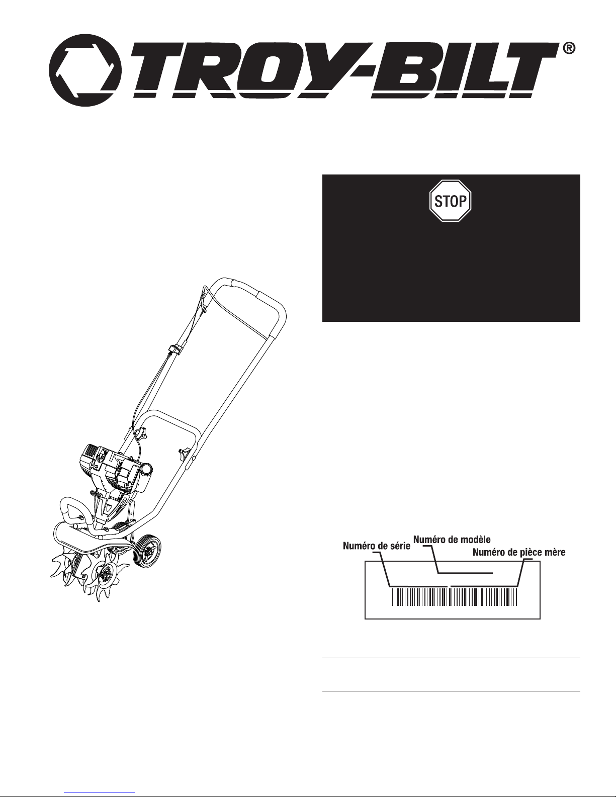
Avant d'assembler votre nouvel équipement, repérez la plaque
signalétique de l'appareil et copiez ses informations dans l'espace ci-
dessous. Ces informations sont essentielles si vous désirez obtenir de
l'aide auprès de notre service technique ou d'un distributeur agréé. Un
exemple de plaque signalétique est présenté ci-dessous.
CONSERVER CES INSTRUCTIONS
F2
LISEZ TOUTES LES INSTRUCTIONS AVANT UTILISATION
• Lisez soigneusement cette notice. Familiarisez-vous avec les
commandes et la marche à suivre pour une bonne utilisation
de l'appareil.
• N’utilisez pas cet appareil lorsque vous êtes fatigué, malade, ou
sous l’influence de l’alcool, de drogues, ou de médicaments.
• Tout enfant ou adolescent de moins de 15 ans ne doit pas
utiliser cet appareil, à moins que l'adolescent soit sous la
supervision d’un adulte.
• Toutes les protections et tous les dispositifs de sécurité doivent
être installés correctement avant utilisation de l’appareil.
• Inspectez l’appareil avant utilisation. Remplacez les pièces
endommagées. Détectez les fuites de carburant éventuelles.
Assurez-vous que tous les accessoires sont bien en place.
Remplacez les pièces susceptibles d’être fissurées, ébréchées,
ou endommagées. N’utilisez pas cet appareil si des pièces ont
du jeu ou sont endommagées.
• Inspectez la zone avec attention avant de démarrer cet
appareil. Retirez tous les débris et objets durs ou tranchants
tels que du verre, les câbles, etc…
• Soyez conscient des risques de blessures à la tête, aux mains
et aux pieds.
• Eloignez les enfants, les personnes à proximité et les animaux
familiers de la zone d’utilisation. Au minimum, faites reculer les
enfants, les personnes à proximité et les animaux familiers de
50 pieds (15 m) ; il existe néanmoins un risque de projectiles
pour les personnes à proximité. Encouragez-les à porter des
lunettes de sécurité. Si quelqu’un s’approche de vous, arrêtez
l’appareil immédiatement.
• Appuyez sur la manette des gaz et vérifiez que le régime du
moteur revienne automatiquement au ralenti. Effectuez tous
les réglages et réparations avant d’utiliser l’appareil.
ALERTES DE SECURITE POUR LES APPAREILS A ESSENCE
• Stockez uniquement le carburant dans des conteneurs prévus
spécifiquement à cet effet et approuvés pour le stockage de
telles substances.
• Evitez tout ce qui pourrait enflammer le carburant renversé. Ne
démarrez pas le moteur avant que les vapeurs de carburant ne
se soient dissipées.
• Coupez toujours le moteur et laissez-le refroidir avant de remplir
le réservoir d’essence. Ne retirez jamais le bouchon du réservoir
d’essence et ne remplissez jamais ce dernier lorsque le moteur
est chaud. Ne démarrez jamais l’appareil sans avoir bien revissé
le bouchon du réservoir d’essence. Dévissez lentement le
bouchon du réservoir d’essence afin de réduire la pression.
• Ajoutez le carburant en extérieur, dans une zone propre, bien
aérée, et dépourvue de toute source d’étincelles ou de flammes.
Dévissez lentement le bouchon du réservoir d’essence
uniquement après avoir arrêté le moteur. Ne fumez pas en
remplissant le réservoir ou en mélangeant le carburant. L’essence
s’étant échappée de l’appareil doit être essuyée immédiatement.
Essuyez l’appareil systématiquement avant utilisation.
• Eloignez l’appareil d’au moins 30 pieds (9,1 m) du site et de la
source du carburant avant de démarrer le moteur. Ne fumez
pas ou assurez-vous qu’il n’y a pas de source d’étincelles et
de flammes, à proximité, lorsque vous ajoutez du carburant
ou faites tourner l’appareil.
LORS DU FONCTIONNEMENT DE L'APPAREIL
• L'appareil ne doit pas être démarré ou opéré à l'intérieur d'un
espace ou d’un bâtiment clos. L’inhalation des fumées
d’échappement peut être fatale. Cet appareil doit fonctionner
uniquement en extérieur, dans une zone bien aérée.
• Portez des lunettes de sécurité conformes aux normes ANSI
Z87.1–1989, lesquelles doivent être indiquées sur les lunettes
mêmes. Portez des bouchons d’oreille et des casques
antibruit lors de l’utilisation de cet appareil. Portez un masque
CONSIGNES DE SÉCURITÉ
• IMPORTANTES CONSIGNES DE SÉCURITÉ •
Lisez le(s) manuel(s) de l'utilisateur et suivez tous les
avertissements et consignes de sécurité. Vous pourriez à défaut
entraîner des blessures graves pour vous ou d'autres personnes.
SI VOUS AVEZ DES QUESTIONS,
APPELEZ LE
1-877-282-8684
AUX ÉTATS-UNIS,
OU LE 1-800-668-1238 AU CANADA
Les symboles de sécurité attirent votre attention sur des dangers
potentiels. Ces symboles et leurs détails explicatifs méritent que
vous les lisiez et compreniez bien. Les avertissements de
sécurité ne peuvent éviter les dangers de par eux-mêmes. Les
consignes ou mises en garde qu'ils donnent ne remplacent pas
des mesures préventives appropriées contre les accidents.
REMARQUE: donne des informations ou des instructions vitales
pour le fonctionnement ou l'entretien de l'équipement.
ALERTE DE SÉCURITÉ : Indique un danger,
un avertissement ou une mise en garde. Soyez vigilant
afin d'éviter toute blessure grave. Ce symbole peut
être combiné à d'autres symboles ou pictogrammes.
DANGER : le non-respect d’un avertissement peut
causer dommages matériels ou blessures graves pour
tous. Respectez les consignes de sécurité afin de réduire
les risques d'incendie, d'électrocution et de blessures.
AVERTISSEMENT : le non-respect d’un
avertissement peut causer dommages matériels ou
blessures graves pour tous. Respectez les
consignes de sécurité afin de réduire les risques
d'incendie, d'électrocution et de blessures.
MISE EN GARDE : le non-respect d’un
avertissement peut causer dommages matériels ou
blessures graves pour tous. Respectez toujours les
consignes de sécurité afin de réduire les risques
d'incendie, d'électrocution et de blessures.
SYMBOLE SIGNIFICATION
PARE-ÉTINCELLES
REMARQUE : à l'intention des utilisateurs opérant dans les terres
forestières des États-Unis et dans les états de Californie, du
Maine, de l'Orégon et de Washington. Toutes les terres forestières
des États-Unis et de l'état de Californie (Codes sur les ressources
publiques 4442 et 4443), de l'Orégon et de Washington exigent de
par la loi que certains moteurs à combustion interne utilisés dans des
zones couvertes de taillis ou d'herbe soient équipés d'un pare-
étincelles en parfait état de fonctionnement, ou qu'ils soient conçus,
équipés et entretenus pour la prévention des incendies. Renseignez-
vous auprès des autorités de votre province ou de votre municipalité
concernant la réglementation en vigueur. Vous pourriez être passible
d'une amende ou être tenu responsable si vous ne respectez pas
cette réglementation. Cet appareil est équipé d'un pare-étincelles en
usine. Si l'écran pare-étincelles, réf. 753-05297, doit être
remplacé, communiquez avec le service technique.
AVERTISSEMENT DE LA PROPOSITION 65 DE CALIFORNIE
AVERTISSEMENT
LES GAZ D'ÉCHAPPEMENT DU MOTEUR DE CET
APPAREIL CONTIENNENT DES PRODUITS CHIMIQUES
CONSIDÉRÉS PAR L'ÉTAT DE CALIFORNIE COMME
POUVANT CAUSER LE CANCER, DES MALFORMATIONS
CONGÉNITALES OU D'AUTRES EFFETS NOCIFS SUR
L'APPAREIL DE REPRODUCTION.
AVERTISSEMENT : Suivez soigneusement les
consignes de sécurité lorsque vous utilisez cet appareil.
Dans l'intérêt de votre sécurité et de celle des personnes
à proximité, prenez soin de lire ces instructions avant de
faire fonctionner la machine. Veuillez garder les
instructions en lieu sûr pour usage ultérieur.
AVERTISSEMENT : L'essence est extrêmement
inflammable et ses vapeurs peuvent exploser si on y
met le feu. Veuillez prendre les précautions suivantes.

F3
CONSIGNES DE SÉCURITÉ
si l'appareil émet de la poussière.
• Portez un pantalon long et épais, des bottes, des gants et une
chemise à manches longues. Ne portez pas de vêtements
amples, de bijoux, de pantalons courts, de sandales et ne
soyez pas pieds nus. Veillez à ce que vos cheveux restent au-
dessus du niveau des épaules.
• Cet appareil dispose d’un embrayage. Les dents reste
immobile lorsque le moteur tourne au ralenti. Dans le cas
contraire, faites ajuster cet appareil par un technicien agréé.
• Assurez-vous que les dens n’est pas en contact avec tout
autre élément avant de démarrer l’appareil.
• Utilisez cet appareil uniquement en plein jour ou si vous
disposez d’un éclairage artificiel suffisant.
• Evitez les démarrages accidentels. Soyez en position de démarrage
lorsque vous tirez sur le cordon du démarreur. L’utilisateur et
l’appareil doivent être sur un sol ferme lors du démarrage. Référez-
vous aux consignes relatives au démarrage/à l’arrêt de l’appareil.
• Utilisez le bon outil. N’utilisez pas un outil pour des fonctions
pour lesquelles il n’a pas été prévu.
• Soyez très prudent lorsque vous faites marche arrière ou que
vous tirez l’appareil vers vous.
• N’étendez pas trop le bras. Restez toujours à distance et en équilibre.
• Tenez toujours l’appareil à deux mains lorsqu'il est en marche.
Assurez une prise ferme sur les deux poignées ou grips.
• Gardez vos mains, votre visage et vos pieds à distance des
parties en mouvement. Ne touchez pas et ne tentez pas
d'arrêter les dents lorsqu'il est en rotation.
• Ne touchez pas au moteur, à la transmission ou au pot
d'échappement. Ces parties deviennent extrêmement chaudes
lors du fonctionnement, même après l'arrêt de l'appareil.
• L'appareil ne doit pas fonctionner à un régime supérieur à
celui adapté pour cultiver. Ne faites pas tourner le moteur à
haut régime lorsque vous ne labourez pas.
• Coupez toujours le moteur lorsque vous interrompez le
labourage ou lorsque vous vous rendez d’un champ à un autre.
• Si vous butez ou bloquez sur un objet, arrêtez le moteur
immédiatement et vérifiez que l'appareil n'a pas été
endommagé. Ne redémarrez pas l'appareil avant de l'avoir
réparé. Ne faites pas fonctionner l’appareil si certaines pièces
ont du jeu ou sont endommagées.
• Arrêtez l’appareil, coupez le moteur, et déconnectez la bougie
avant de l’entretenir ou de le réparer.
• Pour cet appareil, utilisez uniquement les pièces et accessoires
de rechange du fabricant. Ils sont disponibles auprès d’un
fournisseur officiel. L’utilisation de pièces ou accessoires non
agréés pourrait entraîner de graves blessures pour l'utilisateur,
ou endommager l'appareil, et annuler votre garantie.
• Dégagez l’herbe et les autres substances nichées dans
l’appareil. Elles peuvent se coincer entre les dents et l’écran.
• Afin de réduire les risques d’incendie, remplacez les réducteurs
anti-flamme et les pots d’échappement défaillants. Nettoyez
l’herbe, les feuilles, les couches de graisse excessives et les
dépôts de carbone du moteur et du pot d’échappement.
APRES UTILISATION
• Nettoyez les dents à l’aide d’un produit d’entretien d’intérieur
afin de retirer les dépôts. Graissez les dents à l'huile pour
l’empêcher de rouiller.
AUTRES MISES EN GARDE DE SECURITE
• N’entreposez jamais un appareil à essence à l’intérieur d’un
bâtiment où les vapeurs peuvent entrer en contact avec toute
source de flammes ou d’étincelles.
• Laissez refroidir le moteur avant de le ranger ou de le déplacer. Lorsque
vous déplacez l’appareil, assurez-vous qu’il ne pose aucun danger.
• Entreposez l’appareil dans une zone sèche, verrouillée ou hors
de la portée des enfants.
• Ne mouillez ou ne pulvérisez jamais d’eau ou tout autre liquide, sur
l’appareil. Veillez à ce que les poignées restent sèches, propres et
dépourvues de tout dépôt. Nettoyez l’appareil après chaque
utilisation, voir les consignes portant sur le nettoyage et le stockage.
• Conservez ces consignes. Consultez-les souvent et utilisez-les
pour mettre en garde les autres utilisateurs. Si vous prêtez cet
appareil à quelqu'un, donnez-lui ces consignes.
CONSERVEZ CES CONSIGNES
• SYMBOLES DE SÉCURITÉ ET INTERNATIONAUX •
Ce manuel de l'utilisateur décrit les symboles et pictogrammes de sécurité et internationaux pouvant apparaître sur ce produit. Consultez
le manuel de l'utilisateur pour les informations concernant la sécurité, le montage, le fonctionnement, l'entretien et les réparations.
• LISEZ LE MANUEL DE L'UTILISATEUR
AVERTISSEMENT : Lisez le manuel de
l'utilisateur et suivez tous les avertissements et
consignes de sécurité. Vous pourriez à défaut
entraîner des blessures graves pour vous ou
d'autres personnes.
• ÉLOIGNEZ LES SPECTATEURS
AVERTISSEMENT : éloignez tout spectateur,
les enfants et les animaux domestiques en particulier,
d'au moins 15 m (50 pi) de la zone de coupe.
SYMBOLE SIGNIFICATION
• LES OBJETS PROJETÉS ET LA TÊTE ROTATIVE
PEUVENT CAUSER DES BLESSURES GRAVES
AVERTISSEMENT : Ne faites pas fonctionner
sans protecteur de sécurité en plastique. Tenez-
vous à l'écart de l'accessoire de coupe rotatif.
• SYMBOLE ALERTE DE SÉCURITÉ
Indique un danger, un avertissement ou une mise
en garde. Ce symbole peut être combiné à
d'autres symboles ou pictogrammes.
SYMBOLE SIGNIFICATION
• PORTEZ DES PROTECTIONS (YEUX ET
OREILLES)
AVERTISSEMENT : les objets projetés et les
bruits forts peuvent endommager la vue et l’ouïe.
Portez une visière de norme ANSI Z87.1–1989 et
des protège-oreilles pendant l'utilisation.
• NIVEAU D'HUILE
Voir le manuel de l'utilisateur pour le type d'huile
approprié.
• CARBURANT SANS PLOMB
Utilisez toujours du carburant sans plomb frais et
propre.
• COMMANDE MARCHE/ARRÊT
ARRÊT ou STOP
• COMMANDE MARCHE/ARRÊT
ALLUMAGE / DÉMARRAGE / MARCHE
• AVERTISSEMENT SURFACE CHAUDE
Ne touchez pas un silencieux ou un cylindre chaud.
Vous pourriez vous brûler. Ces pièces deviennent
très chaudes à l'utilisation. Elles restes chaudes
brièvement après l'arrêt.
• CONTRÔLE DE L'ÉTRANGLEUR
1. • Position d’étranglement MAXIMUM
2. • Position d’étranglement PARTIEL
3. • Position MARCHE
• CULTIVATEURS – LES DENTS ROTATIVES
PEUVENT BLESSER GRIÈVEMEN
AVERTISSEMENT : Arrêtez le moteur et laissez
les dents s’arrêter avant d’en installer ou en retirer, ou
d’entreprendre un nettoyage ou entretien. Gardez les
mains et les pieds éloignés des dents en rotation.
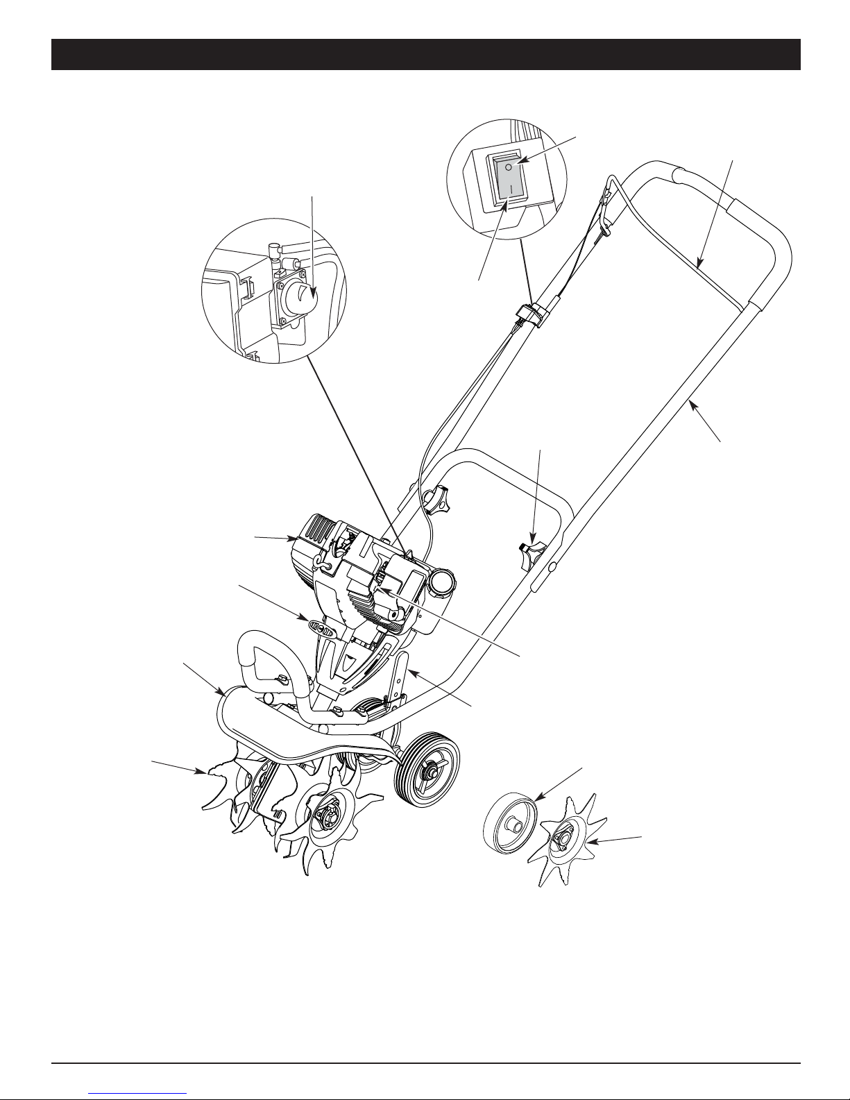
F4
Poignée de la corde
de démarrage
Poire
d'amorçage
Support de la
roue
Bouton du
guidon
Protecteur
des dents
Dents
Support
de la roue
Silencieux
ARRÊT (O)
MARCHE (I)
Manette
des gaz
Guidon
APPLICATIONS
• Travailler le gazon et les sols meubles ou semi meubles.
• Travailler les plates-bandes, autour des arbres, etc.
• Découpage de bord
FAMILIARISEZ-VOUS AVEC VOTRE APPAREIL
Roue du coupe-
bordures
Lame du coupe-
bordures
Table of contents
Languages:
Popular Tiller manuals by other brands


Garland
Garland BULL 1482 NRQG instruction manual

Craftsman
Craftsman Incredi-Pull 316.29256 Operator's manual

ASIA TECHNOLOGY
ASIA TECHNOLOGY TR-60 Operating manual & parts list

Poulan Pro
Poulan Pro PPFT55 owner's manual

Craftsman
Craftsman 917.294483 owner's manual

Parkside
Parkside PGK 1500 A1 Translation of the original instructions


