manuals.online logo
Brands
  1. Home
  2. •
  3. Brands
  4. •
  5. Troy-Bilt
  6. •
  7. Tiller
  8. •
  9. Troy-Bilt 148H User manual

Troy-Bilt 148H User manual

Other manuals for 148H

1

Other Troy-Bilt Tiller manuals

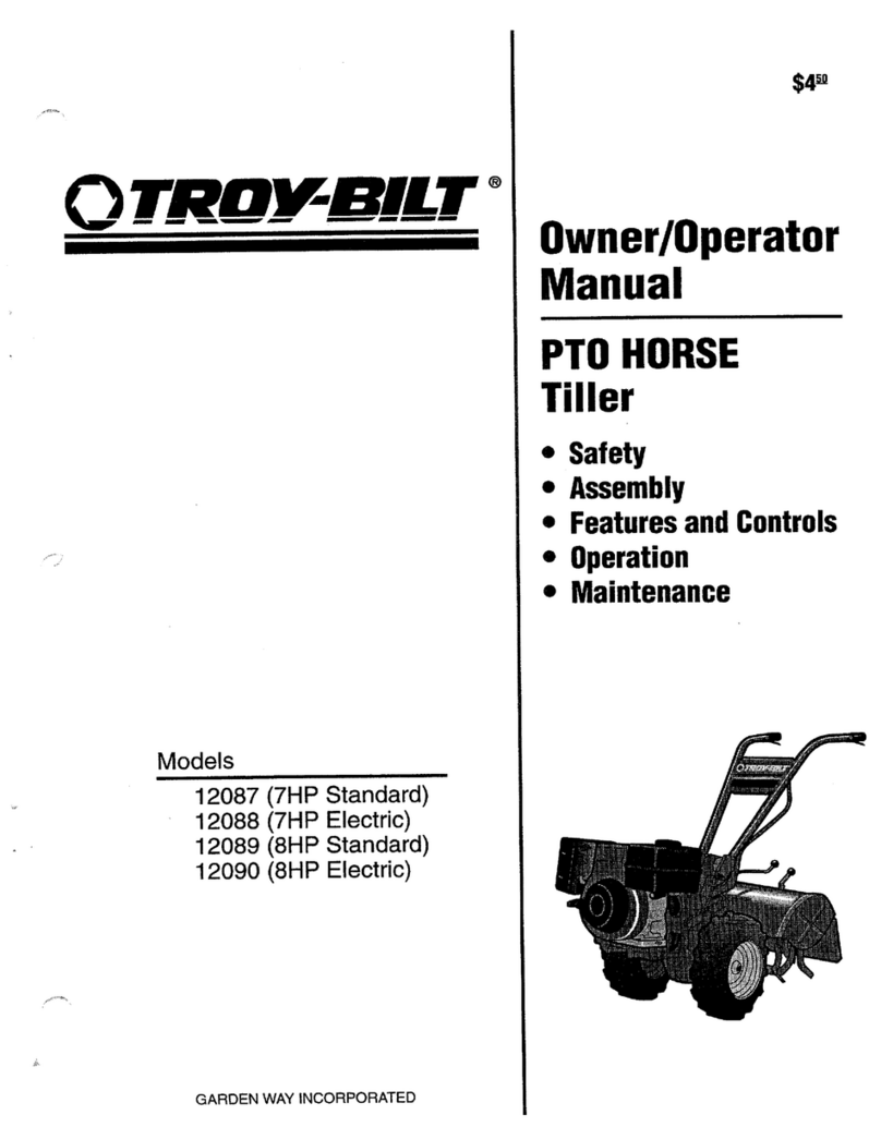
Troy-Bilt PONY User manual

Troy-Bilt

Troy-Bilt PONY User manual

Troy-Bilt 12214 - 5.5HP User manual

Troy-Bilt

Troy-Bilt 12214 - 5.5HP User manual

Troy-Bilt 12097 Owner's manual

Troy-Bilt

Troy-Bilt 12097 Owner's manual

Troy-Bilt 663B- -Pony User manual

Troy-Bilt

Troy-Bilt 663B- -Pony User manual

Troy-Bilt PONY User manual

Troy-Bilt

Troy-Bilt PONY User manual

Troy-Bilt 12155 Owner's manual

Troy-Bilt

Troy-Bilt 12155 Owner's manual

Troy-Bilt 769-00485A P/N 769-00485A User manual

Troy-Bilt

Troy-Bilt 769-00485A P/N 769-00485A User manual

Troy-Bilt PRO LINE 644HMBRONCO User manual

Troy-Bilt

Troy-Bilt PRO LINE 644HMBRONCO User manual

Troy-Bilt TBC304 User manual

Troy-Bilt

Troy-Bilt TBC304 User manual

Troy-Bilt Garden Way 12194 User manual

Troy-Bilt

Troy-Bilt Garden Way 12194 User manual

Troy-Bilt 12001C Owner's manual

Troy-Bilt

Troy-Bilt 12001C Owner's manual

Troy-Bilt TBGC User manual

Troy-Bilt

Troy-Bilt TBGC User manual

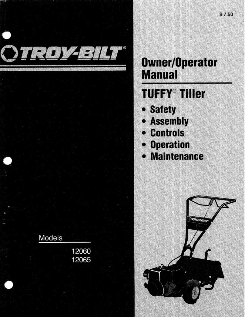
Troy-Bilt TUFFY 630CN User manual

Troy-Bilt

Troy-Bilt TUFFY 630CN User manual

Troy-Bilt Garden way 12215 User manual

Troy-Bilt

Troy-Bilt Garden way 12215 User manual

Troy-Bilt Colt FT User manual

Troy-Bilt

Troy-Bilt Colt FT User manual

Troy-Bilt Econo-Horse 12185 User manual

Troy-Bilt

Troy-Bilt Econo-Horse 12185 User manual

Troy-Bilt 128T User manual

Troy-Bilt

Troy-Bilt 128T User manual

Troy-Bilt Horse E686N User manual

Troy-Bilt

Troy-Bilt Horse E686N User manual

Troy-Bilt 21C-655A766 User manual

Troy-Bilt

Troy-Bilt 21C-655A766 User manual

Troy-Bilt 12097 User manual

Troy-Bilt

Troy-Bilt 12097 User manual

Troy-Bilt OEM-290-101 User manual

Troy-Bilt

Troy-Bilt OEM-290-101 User manual

Troy-Bilt Horse 682J User manual

Troy-Bilt

Troy-Bilt Horse 682J User manual

Troy-Bilt Bronco CRT User manual

Troy-Bilt

Troy-Bilt Bronco CRT User manual

Troy-Bilt TUFFY CRT 640C User manual

Troy-Bilt

Troy-Bilt TUFFY CRT 640C User manual

Popular Tiller manuals by other brands

WIL-RICH 2500 Operator's manual

WIL-RICH

WIL-RICH 2500 Operator's manual

MTD 410R parts list

MTD

MTD 410R parts list

Viking HB 685 instruction manual

Viking

Viking HB 685 instruction manual

SMASH TLG415 instruction manual

SMASH

SMASH TLG415 instruction manual

FarmBoy FB-IC-209P user manual

FarmBoy

FarmBoy FB-IC-209P user manual

Craftsman 247.29931 Operator's manual

Craftsman

Craftsman 247.29931 Operator's manual

MTD FRT Series Operator's manual

MTD

MTD FRT Series Operator's manual

Craftsman 917.298353 owner's manual

Craftsman

Craftsman 917.298353 owner's manual

MTD OHV Series Original operating instructions

MTD

MTD OHV Series Original operating instructions

YAT YT5601-01 Assembly, Use, Maintenance Manual

YAT

YAT YT5601-01 Assembly, Use, Maintenance Manual

Craftsman 917.296010 owner's manual

Craftsman

Craftsman 917.296010 owner's manual

Scheppach MTP560 Translation from the original instruction manual

Scheppach

Scheppach MTP560 Translation from the original instruction manual

GARDEN WAY 12194 owner's manual

GARDEN WAY

GARDEN WAY 12194 owner's manual

Classen STAND-AER SA-25 Operator's manual and parts list

Classen

Classen STAND-AER SA-25 Operator's manual and parts list

Altrad ATIKA BH 1400 N Original instructions, safety instructions, spare parts

Altrad

Altrad ATIKA BH 1400 N Original instructions, safety instructions, spare parts

DR PILOT 2 Safety & Operating Instructions

DR

DR PILOT 2 Safety & Operating Instructions

AL-KO TL 1820 Instructions for use

AL-KO

AL-KO TL 1820 Instructions for use

breviglieri mekfarmer 120 Operating and maintenance

breviglieri

breviglieri mekfarmer 120 Operating and maintenance

manuals.online logo
manuals.online logoBrands
  • About & Mission
  • Contact us
  • Privacy Policy
  • Terms and Conditions

Copyright 2025 Manuals.Online. All Rights Reserved.

0TROI BILT"
Operator's Manual
Tiller/Edger Model
148H
IMPORTANT:READ SAFETY RULES AND INSTRUCTIONS CAREFULLY
Warning: This unit is equipped with an internal combustion engine and should not be used on or near any unimproved forest-covered, brush-cov-
ered or grass-covered land unless the engine's exhaust system is equipped with a spark arrester meeting applicable local or state laws (if any). if a
spark arrester is used, it should be maintained in effective working order by the operator. In the State of California the above is required by law (Sec-
tion 4442 of the California Public Resources Code). Other states may have similar laws. Federal laws apply on federal lands. A spark arrester for the
muffler is available by contacting the service department at Troy-Bilt LLC, P.O. Box 361131 Cleveland, Ohio 44136-0019.
TROY-BILT LLC, P.O. BOX 361131, CLEVELAND, OH 44136-0019
PRINTED IN USA FROM NO. 770-10600
(12/2001 )
TABLE OF CONTENTS
Content Page
Calling Customer Support .................................................... 2
Safety ................................................................... 3
Assembly ................................................................. 5
Features and Controls ....................................................... 6
Operation ................................................................ 7
Maintenance .............................................................. 10
Troubleshooting ............................................................ 12
Storage .................................................................. 12
Parts List ................................................................. 13
Warrany Information ........................................................ Back Cover
FINDINGMODELNUMBER
This Operator's Manual is an important part of your new Tiller/Edger. It will help you assemble, prepare and maintain
the unit for best performance. Please read and understand what it says.
Before you start assembling your new equipment, please locate the model plate on the equipment and copy the infor-
mation from it in the space provided below. This information is very important if you need help from our Customer
Support Department or an authorized dealer.
You can locate the model number by looking at the rear surface of the tine shield. A sample model plate is ex-
plained below. For future reference, please copy the model number and the serial number of the equipment in
the space below
O BILT. TROY-BILT LLI
P. 0. BOX 361131
www.troybilt.com CLEVELAND,OH44136
330-558-7220
•866-840-648_
Copy Model Number Here
Copy Serial Number Here
ENGINEINFORMATION
The engine manufacturer is responsible for all engine-related issues with regards to performance, power-rating, speci-
fications, warranty and service. Please refer to the engine manufacturer's Owner's/Operator's Manual packed sepa-
rately with your unit for more information.
CALLING CUSTOMER SUPPORT
If you have difficulty assembling this product or have any questions regarding the controls, operation or maintenance
of this unit, please call the Customer Support Department.
Call 1- (330) 558-7220 or 1- (866) 840-6483 to reach a Customer Support representative. Please have
your unit's model number and serial number ready when you call. See previous section to locate this in-
formation. You will be asked to enter the serial number in order to process your call ..
Safety
Safety AlertSymbol
,_ This isa safety alert symbol. It is usedin this
manualand on the unit to alert you to potential haz-
ards. Whenyou seethis symbol, readand obeythe
messagethat follows it. Failureto obey safety mes-
sages could result in personalinjury or property damage.
This machine meets voluntary safety standard
B71.8 - 1996, which is sponsored by the Outdoor
Power Equipment Institute, Inc., and is published by
the American National Standards Institute.
•ILWARNING
Theengineexhaustfromthis productcontainschemi-
calsknowntothe State ofCaliforniatocausecancer,
birthdefectsor otherreproductiveharm.
TRAINING
• Readthis Owner's Manualand the sep-
arate EngineOwner's Manualvery care-
fully beforeoperatingthis equipment. Be
completely familiar with the controls and
the proper useof the equipment. Know
howto stop the unit and disengagethe
controls quickly. A replacementManual
isavailableby contacting your authorized
dealer or the Factory.
•Neverallow children or untrained
adults to usethis equipment. Letadults
operatethe unit only if instructed
properly.
• Keepthe area of operationclear of all
persons,particularly small children and
pets. Keepbystandersat least 25 feet
from thearea of operation.
• Keepin mind that the operator or user
is responsiblefor accidents or hazards
occurring to other people,their property
and themselves.
• Familiarizeyourself with all of the
safety and operating decals onthis equip-
ment and on any of its attachments or
accessories.
• Donot run engine in an enclosed area.
Engineexhaustcontains carbon
monoxide gas,a deadly poisonthat is
odorless, colorless, andtasteless. Donot
operatethis equipment nearbuildings,
windows, or air conditioning equipment.
• Donot allow handsor any other part of
the body or clothing near the rotating
tines or nearany other moving part. The
tines begin to rotateforward oncethe
engine is started and the Throttle/Tines
Control Leveris squeezed. Thetines con-
tinue to rotate until the operator releases
the Throttle/Tines Control Lever.
• Beforeinspecting or servicing any part
of the equipment, shut off engine,make
sure all moving parts havecome to a
complete stop, then disconnect spark
plug wire from spark plug and movewire
away from the plug.
•Donot operatethis equipment if you are
underthe influence ofalcohol, medication,
or whenyou aretired or ill.
PREPARATION
•Thoroughly inspectthe area wherethe
equipment isto be usedand remove all
foreign objects.
• Makesure that the Throttle/Tines Con-
trol Lever is disengagedand is in the neu-
tral position beforeyou beginto start the
engine.
•Do notoperatethe machinewithout
wearing adequateouter garments. Avoid
loosegarments or jewelry that could get
caught in moving parts of the machine or
its engine.
• Do notoperatethe equipment when
barefoot or when wearing sandals,
sneakers, or similar lightweight footwear.
Wear protectivefootwear that will protect
your feet and improve footing on all
surfaces.
• Wearapprovedsafety glasseswhen op-
erating this equipment. Theoperation of
any poweredmachine can result in for-
eign objects beingthrown by high-speed
rotating parts.
• Do nottill nearunderground electric
cables,telephonelines, pipes, or hoses.
If in doubt, contact your utility or tele-
phonecompanyto locateunderground
services.
• Handlefuel with care. It is highly
flammable and hasexplosivevapors.
Takethese precautions:
a. Useanapproved fuel container.
b. Add fuel beforestarting the engine.
Never removethe capof the fuel
tank or add fuel while the engine is
running or whenthe engine is hot.
Operatorsshall not smoke.
c. Keepmatches,cigarettes,cigars,
pipes, openflames, and sparks
awayfrom the fuel tank and fuel
container.
d. Fillfuel tank outdoors andwith ex-
treme caution. Neverfill fueltank
when indoors. Useafunnel or
spout to prevent spillage.
e. Replaceall fuel tank and fuel con-
tainer capssecurely.
f. If fuel is spilled, do not attempt to
start the engine,but movethe ma-
chineaway from the areaof spillage
andavoid creating any source of ig-
nition until fuel vapors have
dissipated.
• Nevermakeadjustments to your equip-
ment whenthe engine is running or spark
plug wire isconnected (unless specifically
recommendedin Owner's Manual).
OPERATION
Operator'sPosition
RIGHTSID_ LEFTSIDE
LEFTandRIGHTsidesofthetillerare
fromtheoperator'spositionbehindthe
handlebars(unlessnotedotherwise).
•Thecorrect operator's position is when
you are standing behindand gripping the
handlebar,facing forward toward the
engine. Do not leavethis position while
usingthe engine Throttle/Tines lever.
• Donot put handsor feet near or under
rotating parts.
3
Section1: Safety
•Exerciseextremecaution when on or
crossing graveldrives, walks or roads.
Stay alert for hidden hazardsor traffic.
Donot carry passengers.
• After striking aforeign object, stop the
engine, letall moving parts come to a
complete stop, disconnect the spark plug
wire and prevent it from touching the
spark plug,then carefully inspectthe ma-
chine for damage. Repairthe damage
beforerestarting and operating the
machine.
• Exercisecaution to avoid slipping or
falling.
• If the machineshould start to vibrate
abnormally, stop the engine. Disconnect
the spark plug wire and prevent it from
touching the plug. Checkimmediately for
the cause. Vibration is generallya
warning oftrouble. Fixthe problem
beforeusing the equipment again.
• Stopthe engine,disconnect the spark
plug wire and preventit from touching the
spark plug wheneveryou leavethe equip-
ment, beforeunclogging the tines, or
when making any repairs, adjustments or
inspections.
• Takeall possible precautionswhen
leavingthe machineunattended. Always
stop the engine. Disconnectthe spark
plug wire and preventit from touching the
plug.
• Beforecleaning, repairing, or
inspecting, stop the engine and make
certain all moving parts havestopped.
Disconnectthe spark plug wire and
preventit from touching the spark plug to
avoid accidentalstarting.
• Neveroperateequipment without
proper guards, plates,or other protective
safety devicesin place.
• Donot run the engine in an enclosed
area. Theexhaustfumes from the engine
contain extremelydangerous carbon
monoxide gas. This gas is colorless,
• Beaware that the equipment may unex-
pectedlybounceupward or jump forward
if thetines should strike extremely hard
packedsoil, frozen ground, or buried ob-
stacles such as large stones, roots or
stumps. If you are in doubt aboutthe
tilling conditions, always usethe fol-
lowing operating precautionsto assist
you in maintaining control of the
equipment:
a. Standbehind theequipment, using
both handson the handlebars.
Relaxyour arms, but usea secure
handgrip.
b. Start tilling at shallow depths,
working gradually deeperwith each
pass.
c. Clearthe tilling areaof all large
stones, roots, and other debris.
d. Inan emergency,stop thetines by
releasingthe engineThrottle/Tines
leveron the handlebar. Tostop the
engine, movethe engine On/Off
switch to OFE
• Do notoverloadthe machine'scapacity
byattempting to till too deeplyat too fast
a rate.
• Neveroperatethe equipment on slip-
perysurfaces. Look behind and use care
when backing up.
• Do notoperatethe equipment on a
slope that istoo steepfor safety. When
on slopes,slow down and makesure you
havegood footing.
•Neverallow bystanders nearthe unit.
• Onlyuseattachments and accessories
that are factory-approved.
• Neveroperatethe equipment without
good visibility or good light.
•Neveroperatethe unit if you aretired,
or under the influence of alcohol, drugs,
or medication.
•Do nottamper with the engine gov-
ernor settings on the machine;the gov-
odorless, tastelessand deadlypoisonous rn r ntr I th
;e o co os emaximumsafeoper-
• Keepchildren and pets away. ating speedand protects the engine and
all other moving parts from damage
• Donot touch engine parts which may
be hotfrom operation. Allow parts to
cool beforeinspecting, cleaningor
repairing.
• Remember:you canstop thetines by
releasingthe engineThrottle/Tines lever.
Movethe engine On/Offswitch to OFFto
shut the engineoff.
• Nevertransport this machinewhenthe
engine is running.
• Terminalsand non-insulated electrical
parts shall be protectedagainst shorting
during normal servicing, refuelingor
lubrication.
• Useextremecaution when reversing or
pulling the machinetoward you.
• Start the enginecarefully according to
instructions and with feet well away from
the tines.
MAINTENANCE/STORAGE
•Keepthe tiller, attachments and acces-
sories in safe working condition.
• Checkall nuts, bolts, and screws at fre-
quent intervals for proper tightness to be
sure equipment is in safe working
condition.
• Neverstore equipment with fuel in fuel
tank insidea building wherefumes may
reachan open flame or spark (hot water
and space heaters,furnaces, clothes
dryers, stoves, electric motors, etc.).
• Allow theengine to cool beforestoring
the equipment.
• Keep the enginefree of grass, leaves,
or greaseto reducethe chanceof a fire
hazard.
• Storegasoline in a cool, well-ventilated
area,safelyaway from anyspark- or
flame-producing equipment. Storegaso-
line in an approvedcontainer,safelyaway
from the reachof children.
• Neverperform maintenancewhen
engine is running or spark plug wire is
connected unless instructed to do so.
• If fuel tank must be drained,do so out-
caused byengine overspeed. Authorized doors.
service shall be sought if a problem
exists. •Follow manufacturer's recommenda-
tions for safe loading, unloading,trans-
port and storage of machine.
4
To preventpersonalinjuryor propertydamage, do notstart
the engine until all assembly stepsare completeand you
haveread and understandthe safetyand operatinginstruc-
tionsin this manual.
INTRODUCTION
Carefullyread these instructions in their entirety beforeyou
attempt to assembleor operateyour new equipment.
The Border EdgerAttachment (D, Figure1) does not needto
be installed until you are readyto do edging projects (referto
instructions in Section 4).
UNPACKINGINSTRUCTIONS
1. Inspectyour machine immediately. If you find or suspect
damageto the carton or contents, contact your localautho-
rizeddealeror the Factoryfor assistance.
STEP2: InspectandTightenHardware
Checkall nuts,bolts and screws on your unit and tighten as
needed.
ToolsNeededtoCheckfor LooseHardware:
•Adjustablewrench
• Slotted-headscrewdriver
• Phillips-headscrewdriver
• 7/16" socket and extension
(to checkhardwareat endsof handlebar)
STEP3: AddMotorOilto Engine
IMPORTANT:Theengine isshipped without oil in the
crankcase. Donot start the enginewithout first adding motor
oil. Severeengine damagewill result if the engine is run
without motor oil.
2. Removeany packingmaterial. Checkfor looseparts
1. Referto the separateEngineOwner'sManualfor motor oil
specifications andcapacities.
2. Add oil as described in the EngineOwner'sManual (the
beforediscarding the packing materialor carton. Looseparts engine is a verticaltype, GX31 model).
includethe following:
(1) Wheel (for edging)
(1) EdgerTine
(2) *Long Bushings
(1) *Short Bushing
*Packedin a separateplastic bag.
3. Perform theassembly on a clean, levelsurface. Becareful
notto severelybendany of the control cables on the unit.
ASSEMBLYSTEPS
STEP1: UnfoldandAdjustHandlebars
IMPORTANT: Be careful not to pinchany control cables.
Pushthecables out and away beforeswiveling the handle-
bars.
1. Loosenthe two handlebarknobs (A, Figure1) and unfold
the handlebarsinto the operating position. Do not useforce
-- if there is binding, continue to loosenthe knobs.
2. Therearetwo heightsetting holes inthe upperhandlebar.
The unit is shippedwith the handlebarknobs in the lowest
heightsetting holes. If this height is correct for you,simply
tighten the two handlebarknobs. If desired, reposition the
handlebarknobs, mounting screws and washers in the other
set of holes.
3. Checkthe six (6) plastic ties (C, Figure1). Ties must be
positioned asshown.
NOTE:There is only one handlebarstorage position -folded
over and down as originally shipped.
C\
Figure I
FeaturesandControls
KNOWYOUREQUIPMENT
READTHIS OWNER'SMANUALANDALL SAFETYRULESBEFOREOPERATINGYOUREQUIPMENT.Knowthe location andfunction
of all featuresand controls on the equipment. Savethis manualfor future reference.
Before operating your machine, carefully read and under-
stand all safety, control, and operating instructionsin this
Manual, the separate Engine Owner's Manual and on the
decalsonthe machine.
Failureto follow these instructionscan resultin seriousper-
sonalinjury.
HandlebarHeightAdjustmentKnob(B, Figure2)
Two height settings, plus a storage position are available.
Referto Assembly Steps, STEP1 in Section 2 for adjustment
instructions.
Tilling DepthAdjustmentKnob(C, Figure2)
Looseningthe knob enablesyouto movethe wheel bracket(K)
up or down on the height adjustment bar (L). This controls the
tilling depth.
IMPORTANT:Donot move the wheelbracketany higher than
the top of the adjustment bar.
AdjustableTinePatterns(D, Figure2)
Thefour tine sections arearranged from thefactory for max-
imum performance undera wide variety of conditions. If
needed,the tines canbe arrangedfor narrower tilling or close
A,/_,,{_,_,,,. cultivating. Thetines canalso bearranged to till very stony
soil. SeeAdjusting TinePositions in Section 4 for details.
_/_' I_ _"_'_ CarryingHandle(E, Figure2)
j,.,_"/_i_ _ _:J Whenthe handlebaris folded in the storage position the unit
Jf/ / _ _ can be carried bythe carrying handle. Thecarrying handle
!/ a,sosorvosasat,e-downanchorpo,nt
/ // EdgerAttachment(H, Figure2)
r_Usethis separateattachment to create borders or edgesalong
j// walks, driveways,flower beds, etc. SeeSection 4 for details on
\//
B"/_.,v... IEngineControls
J FuelPrimerBulb(Section4, Figure4)
J._y" Usethe FuelPrimer Bulbto help start the engine under certain
/'J// conditions. SeeStopping and Starting theEnginein Section 4
_._ Band the EngineOwner's Manualfor details.
EngineChoke(Section4, Figure5)
CUsethe EngineChokeleverto help start the engine. Theposi-
tion of the leveris dependenton whether the engine is cold or
warm. SeeStopping and Starting the Engine in Section 4 and
._.._._K the EngineOwner's Manualfor details.
LEngineOn/OffSwitch(A, Figure2)
_)/// Usethe ON/OFFSwitch to start or stop the engine. SeeStop-
!_//// ping and Starting the Enginein Section 4 for details.
EngineRecoilStartRope(F, Figure2)
Usethe recoil start rope to start theengine. See Stoppingand
Starting the Enginein Section4 for details.
Figure2:Featuresandcontrols. Throttle/TinesControlLever (G, Figure2)
UsetheThrottle/Tines Control Leverto start and stop tine rota-
tion. This leveralso varies tinespeed. Releasethe leverto
stop all fine motion. SeeSection4 for more details on this
control.
6
Operation
Beforeoperatingthe unit, carefully read
and understandall safety, controland
operating instructions in this Manual,
the separate Engine Owner's Manual
and thedecalson themachine.
Failure to follow these instructionscan
resultin seriouspersonalinjury.
PRE-STARTPREPARATION
Beforestarting the engine,performthe
following checksand services:
1. Disconnectthe spark plug wire from
the spark plug.
2. Movethe engine On/Offswitch to the
OFFposition.
S. Checkthat all wires and cablesare
properlyand securelyconnected.
4. Checkthe six plastic cableties (J,
Figure2). Besure that cablesand ties are
positioned asshown. Cablesmust not be
kinkedor jammed in the handlebar.
5. Adjust handlebarheight to desired po-
sition (seeSection 2).
6. Checkhardwarefor tightness.
7. Checkengine oil level (seeEngine
Owner's Manual).
8. Checkthe air filter (seeEngine Owner's
Manual).
9. Adjust thetilling depth asfollows:
a. Loosentilling depth adjustment
knob (A, Figure3).
Figure3
b. Movewheel bracket (B,Figure3) up
in relation to heightadjustment bar
(C). Moving bracketupward results
in shallower tilling, which is recom-
mendedfor initial use.
IMPORTANT:Do not movethe wheel
bracketany higherthan thetop of
the adjustment bar.
c. Retightenthe depthadjustment
knob.
10. Reconnectthe spark plug wire.
GASOLINEIS HIGHLYFLAMMABLEAND
ITSVAPORSAREEXPLOSIVE.
Followthe gasoline safety rules in this
Manual (Section1) and in the separate
EngineOwner'sManual.
Failureto follow gasolinesafetyinstruc-
tions can result in serious personal
injuryand propertydamage.
11. Add gasolineto the fuel tank.
IMPORTANT:Readthe separateEngine
Owner'sManualbeforestarting the
engine. Never usestale or contaminated
gasoline or oil/gas mix. Theengine must
bestopped and cool beforeadding gas.
Fillthefuel tank with unleadedgasoline
(with a pump octane rating of 86 or
higher) according to the directions in the
separate EngineOwner's Manual. The
engine is a verticaltype, GX31 model.
STOPPINGAND
STARTINGTHEENGINE
SteppingtheEngine
Do not squeezethe Throttle/TinesCon-
trol Leverwhile startingengine.
Tinesmay propelthe machineforwardif
the engine speedis advancedfrom idle.
Failureto complycanresult in personal
injuryor propertydamage.
Tostop the engine,movethe On/Oft
Switch (A, Figure2) to the OFFposition.
NOTE:TheOn/Oftswitch wire must be
securelyconnectedat both ends. Check
regularlyto ensure that the switch wire is
securelyconnectedto the switch and the
engine.
Starting the Engine
NOTE:Do not squeezeEngine
Throttle/Tines Control Lever(G,Figure2)
when starting engine.
Figure4: Primerbulb(A)andfuel-return
tube(B).
Figure5: Chokelever.
1. Movethe On/OffSwitch (A,Figure2)
to the ONposition.
2. Tostart a cold engine, movethe choke
lever(C, Figure5) to the CLOSEDposi-
tion. Torestartawarm engine, leavethe
choke lever in the OPENposition.
3. Tostart a cold engine,or after refueling
an engine that hasrun out of fuel, press
the priming bulb (A, Figure4) repeatedly
untilfuel can beseenin the clear-plastic
fuel-return tube (B). Torestart awarm
engine, it is not necessaryto press the
priming bulb.
4. Moveto the starting position (Figure
6), keepingyour feet positioned safely
awayfrom the tines.
5. Placeone hand on the upper handlebar
to stabilize the machine.Usethe other
handto pull the recoil start rope lightly
until you feel resistance,then pull briskly.
Letthe rope rewind slowly after eachpull.
NOTE:An alternate stabiliza-
tion method is to stand in
the starting position
(Figure6), but placeone
handon thecarrying
handlewhile pulling the
starter ropewith the
other hand.
6. ifthe choke lever
was movedto the
CLOSEDposition to
start the engine,grad-
uallymove itto the
OPENposition as the
engine warms up. Figure6 7
Section4: Operation
8
A
Figure7: Tinepatterns.
TILLINGANDCULTIVATING
Keepawayfrom rotatingtines. Rotating
tines will causeseriouspersonalinjury.
Useyour machinefor busting sod,
preparing seedbedsand for cultivating in
gardensand flower beds. It is easyto op-
erate, but it is important that you start out
slowly and readthis Section thoroughly
beforeputting itto use. Letthe machine
do most of the work. Thetines will pull
the machine forward, letting you adjust
forward speed by pressing down or lifting
the handlebars.
1. Rollthe machine to thework area.
2. Adjust the tilling depth to the desired
position (seePre-Start Preparationon the
previous page).
3. Start the engine (seeStopping and
Starting theEngineon the previous
page). Standbehind the handlebarand
pushdown on the bar to raisethe tines
off the ground. Squeezethe
Throttle/Tines Lever-the engine should
speedup andthe tines start rotating. Re-
leasetheThrottle/Tines Leverto return to
idle,thetines should stop rotating or they
may rotate very slowly. Lowering them
backto the ground should stop any rota-
tion.
NOTE: if tines continue to rotatewhen
engine is idling, eitherthe idle speedis
too high or the centrifugal clutch is mal-
functioning. If this occurs, contact the
Factoryor your local authorizeddealer.
4. Squeezethe Throttle/Tines Leverto
start thetines rotating. Lowerthe tines to
begintilling. Firmly hold the handlebarto
preventthe machinefrom moving for-
ward too quickly and to allow enough
time for the tines to dig deeplyenough.
Adjust engine speedto suit the tilling
conditions. Rememberthat the rotating
tines help to pull the machine forward.
Useslower speedsanda shallow depth
settingwhen learning to usethe unit and
whenever youare tilling on hard, rough or
unevenground.
5. Donot try to till too deeplyin the first
passthrough sod or very hard ground. If
the machinejumps or bucks, usea shal-
lower depth settingand reducethe engine
speed. With eachsucceedingpass,till
more deeply.
6. Apply downward pressure on the han-
dlebarsfor shallower tilling. Liftthe han-
dlebarsto dig more deeply. If the ma-
chinestays and tills in one spot, try
swinging the handlebarsfrom side to side
to start it moving forward again.
7. Foreasiertilling, water very hard soil a
few days beforetilling. Avoid working the
soil when soggy or wet. Wait a day or
two after heavyrain for the ground to dry.
Cultivating
1. Cultivating is shallow tilling that dis-
rupts weeds and aeratesthe upper crust
of soil.
2. Donot till deeperthan 1"-2"to avoid
injuring nearbyplant roots. Cultivate
often,so that weedsdo not grow large
and cause needlesstangling in the tines.
3. With careful planning,you canspace
the seed rows far enough apartto allow
sufficient room for the machine to culti-
vate after the plants havegrown.
AdjustingTine Positions
Dependinguponthe tilling project,you
havea choice of three tine patterns:
Wide(Standard)TinePositions- As
shippedfrom the factory, the unit is set
up for general tilling and cultivating. This
10"wide tine pattern (the maximum tilling
width) usesall four tine sections
(A, Figure7). See TineRemovalandln-
stallationin Section5 for detailedinforma-
tion on how to set upthis tine position.
NarrowTine Positions- Fora narrow,
4-1/2"tilling width, removethe outside
tine section on the left- and right-sides
(B, Figure7). See TineRemovalandln-
stallation in Section5 for detailedinforma-
tion on howto set upthis tine position.
StonySoilTine Positions- Whentilling
deeplyin stony soil, stones may become
jammed betweenthe inner tines andthe
machine hood. This setup swapsthe two
inner tines to minimize jamming (C,
Figure7). See TineRemovaland Installa-
tion in Section5 for detailedinformation
on how to set upthis tine position.
Tilling Patterns
1. To makeseedbeds,go overthe same
pathtwice in the first row, then overlap
one-halfthe machine width on eachsuc-
cessivepass until all rows aretilled twice
(D, Figure8).
D E
Figure8:RecommendedTillingPattern.
2. Makea second pass ata right angle
across the original passes. Again,
overlapeachpass (E, Figure8). Hard
ground maytake threeto four passes
beforethe desireddepth is achieved.
NOTE: Forsmall gardens, overlap by
one-half (1/2) the machine width, fol-
lowed by successivepassesat one-
quarter (1/4) machinewidth. This over-
lapping method assuresthorough tilling.
MakingBorderEdges
Usethe EdgerAttachment to makeclean,
sharp edgesnextto walkways, driveways,
paths, plantedareas,patios, etc. See In-
stalling and Using the EdgerAttachment,
in this Section, for detailed information.
Section4: Operation
INSTALLINGAND USING
THEEDGERATTACHMENT
Contact with rotating tines or other
moving parts can cause serious per-
sonalinjury.
Before installing or removing attach-
ments, or adjustingor servicingthema-
chine, stop the engine, let all moving
parts cometo a completestop, discon-
nect the spark plug wire and move the
wire awayfrom thesparkplug.
Tocreate borders or edgesnearwalks,
driveways, flower beds,etc., you must
removethe four tine sections and install
the EdgerAttachment (this attachment
was supplied with the unit - see
Section 3).
Installingthe EdgerAttachment
1. Gathertogether the following parts:
Border/EdgerTine(A, Figure10); Long
Bushing(B); Border/EdgerWheel(C); and
Short Bushing(D).
2. Propthe machinecarefully onto the
front of thetubular carrying handle. The
work surface should be firm and flat.
NOTE:Typically,the Border/EdgerTineis
mounted on the right sideof the unit for
right-handed people,and on the left-side
of the unitfor left-handed people.
3. Flipopenand removethe two ring lock
pins (E,Figures9 and 10) on eachtine
shaft.
E
Figure9: Ringlockpinandtines.
Keepleft and right-side tines separateand
markedfor easierreinstallation.
IMPORTANT:The ring lock pin is under
spring tension -usecarewhen removing
or replacingthe ring lock pin.
4. It is important for propertilling perfor-
mancethat the tine sections belater rein-
stalled in their original positions. There-
fore, markthe position of eachtine section
(Left-Outer,Left-Inner,etc.) beforere-
moving them. Referto Figure7 for tine
position information.
5. Installthe short bushing (D, Figure10)
ontothe tine shaft. Thenplacethe
Border/Edgerwheel(C) onto the same
shaft -the wheel hub should facetoward
the tiller. Insert the ring lock pin through
the rounded side of the tine shaft and
snapthe ring down overthe shaft (see
"DETAIL",Figure10).
6. Slide the long bushing (B, Figure10)
ontothe opposite side shaft. Then install
the Border/Edgertine (A) and secure it
with the ring lock pin.
A
Figure 10:Border/Edgertine assemb/y.
Usingthe EdgerAttachment
The EdgerAttachment makesclean, sharp
edgesnext to walkways, driveways,
paths,plantedareas, patios,etc.
Takeyour time when
edging. Decidehowfar
away to edgethe walk or
drive, thenslowly pro-
ceedusing the walk or
drive as your sight _ _
Attachments
Thefollowing Tiller/Edgerattachments areavailablewherethe Tiller/Edgerwas purchased. Seeyour local authorized dealeror con-
tact the Factoryfor details.
PowerLawnRakeAttachment- Model 0EM-290-263 LawnAeratorAttachment- Model0EM-290-264
The PowerLawn Rakehelpsto keep
your lawn healthyand vigorous.
Mattedgrass and debris looks
unattractiveand stifles lawn
growth and overallhealth.
This attachment mounts
without tools and features
dozens of tempered steel
"fingers" that penetrate
and loosenmatted grass
without disturbing root
growth. An 18"-wideswath
covers a large lawnarea quickly.
TheLawnAerator Attachment helps
to promote healthy,denselawns
by looseningand aerating the
soil for better root growth.
Fourtempered steel tines
puncture the surface
of the lawn thus allowing
nutrients to reachthe
roots more easily. This
attachmentassembles
without tools.
Maintenance
Before inspecting,cleaningor servicing
the machine, shot off engine, let aii
moving parts come to a complete stop,
disconnectthesparkplugwire andmove
the wire awayfrom thesparkplug.
Failure to follow these instructionscan
result in personal injury or property
damage.
EQUIPMENTMAINTENANCE
TransmissionMaintenance
Thetransmission was lubricated at the
factory and should not require anyfurther
lubrication.
However,you should checkthe lubricant
levelafter the first five (5) hours of opera-
tion and everytwenty-five (25) operating
hoursthereafter. If needed,usea high-
quality, automotive-grade petroleum-
basedgrease.
Before tipping engine or equipment to
service transmission, drain fuel from
tank by runningengine until fuel tank is
empty. Allow enginetocool.
Tocheckthetransmission:
1. Stop the engine,let it cool and discon-
nect thespark plug wire.
2. Placethe machinedown on its left side
so the right end of the tine shaft facesup.
3. Removethe right-side tines (see Tine
Removaland Installation in this Section).
4. Cleanthe transmission housing.
5. Removethethree threadedplugs (A, B
and C, Figure11) from the transmission.
I 8 ",B °
j Jr
Figure11:Transmissionlubricantcheckand
filllocations,
REQUIREDMAINTENANCESCHEDULE
REQUIRED MAINTENANCE Before First Every3 Every6
Perform at every indicated month or Each month months months
_perating hour interval, whichever Use or !0 Hrs. or 25 Hrs. or 50 Hrs.
somes first.* SeeEngine Owner's Manual
lor engine related maintenance,
CheckTightness of Bolts and Nuts x
CheckTransmission Lubricant Level x (1) x
glean Machine x
CleanTine Shaft x
EngineOil Level Check x
Change x x
_,irCleaner Check x
Change x (2)
Spark Plug Check/Clean x
Replace
goofingFins Check x
SparkArrester Clean x
FuelTank Clean x
FuelFilter Check x
ClutchShoes Check x(3)
Idle Speed Check-Adjust
CalveClearance Check-Adjust
FuelTubes Check Every 2years(Replaceif necessary) (3)
*Forcommercialuse,loghoursofoperationtodeterminepropermaintenanceintervals.
[1)Checkafterfirst5 hoursofuse.
[2)Servicemorefrequentlywhenusedindustyareas.
[3) itemshouldbeservicedby your servicing dealer, unlessyouhavethepropertoolsand
aremechanicallyproficient.
Yearly Every
2 years
X
x(3) x(3)
Lubricant should bevisible in the top two
holes(B and C). If so, replaceall three
plugs. If lubricant is needed,proceedas
follows.
To lubricate thetransmission:
1. Placethe nozzle(D, Figure11) of a
standard greasegun firmly against the
rim of the middle hole (B) and add grease
until it beginsto seepfrom the bottom
hole (A). Reinstallthe plug in the bottom
hole (A). Nextapply greaseto thetop fill
hole (C)until it beginsto seepfrom the
middle hole (B). Reinstallthe plugs in the
middle (B) and top (C)holes.
2. Before reinstalling the tines, usea fine
grade sandpaperto cleanany rust off the
tine shaft. Apply a few drops of oil to the
tine shaft to makefuture tine removal
easier.
OtherLubricationPoints
•HandlebarAdjustment Knobs: Spray
occasionally with a silicone type lubri-
cant.
•Throttle/Tines Control LeverCable:
Squeezethe leverclosed and spray a lu-
bricant into the cablearea.
•TineShaft: After eachuse, removethe
tines,cleanthe tineshaft with sandpaper
and applya lightcoat of oil to the tine
shaft.
Hardware/ElectricalConnections
Beforeeachuse, checkthat all hardware
istight and that the On/OffSwitch wire
connections aresecure. Also checkthat
the switch wiring is in good condition.
lO