manuals.online logo
Brands
  1. Home
  2. •
  3. Brands
  4. •
  5. Troy-Bilt
  6. •
  7. Lawn Mower
  8. •
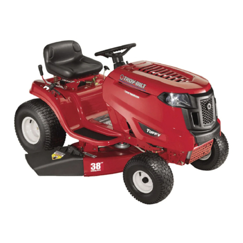
  9. Troy-Bilt V809H User manual

Troy-Bilt V809H User manual

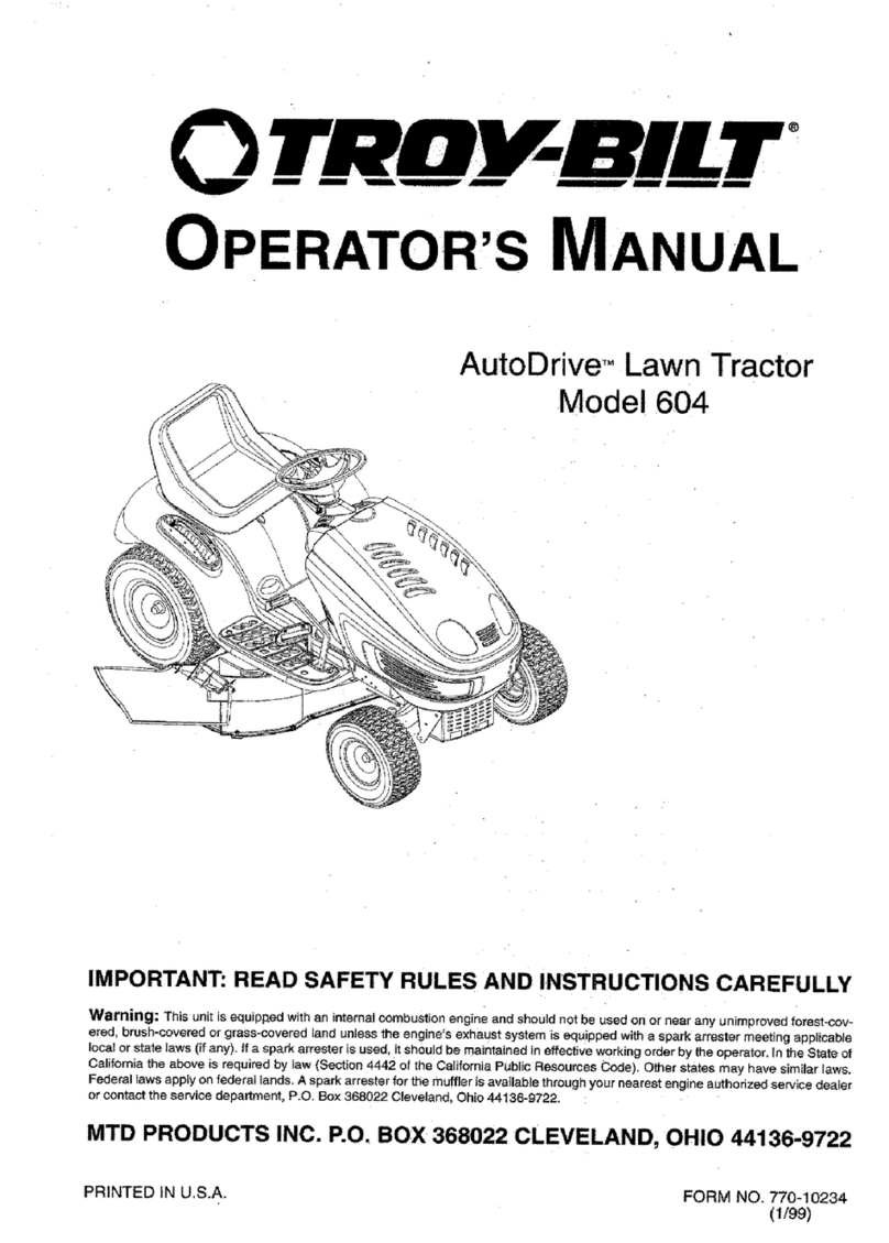
Operator’s Manual
PRINTED IN U.S.A.
FORM NO.
770-10189C.fm
(3/2001)
IMPORTANT: READ SAFETY RULES AND INSTRUCTIONS CAREFULLY
Pedal Drive Garden Tractor
Models V809H
Warning: This unit is equipped with an internal combustion engine and should not be used on or near any unimproved forest-covered,
brush-covered or grass-covered land unless the engine’s exhaust system is equipped with a spark arrester meeting applicable local or
state laws (if any). If a spark arrester is used, it should be maintained in effective working order by the operator. In the State of California
the above is required by law (Section 4442 of the California Public Resources Code). Other states may have similar laws. Federal laws
apply on federal lands. A spark arrester for the muffler is available through your nearest engine authorized service dealer or contact the
service department, P.O. Box 368022 Cleveland, Ohio 44136-9722.
Y809P
MTD PRODUCTS INC. P.O. BOX 368022 CLEVELAND, OHIO 44136-9722
TROY-BILT
®
is a registered trademark owned by Garden Way Incorporated of Troy, New York.
26
SECTION 12: MODELS V809H & Y809P PARTS LIST
97
11
(for choke)
13
4
12
6
9
22
18
19 20
8
10
14
10
5
10
5
16
15
1
17
5
24
3
2
21
23
30
31 26
28
27
29
27
Models V809H & Y809P
REF.
NO.
PART
NO. DESCRIPTION
1 710-0227 Self-tapping Screw, #8-18 x .5
2 710-0599 Self-tapping Screw, 1/4-20 x .5
3 710-0604A Self-tapping Screw, 5/16-18 x .625
4 710-1237 Screw, #10-32 x .625 (Model V809H)
5 710-1314 Socket Cap Screw, 5/16-18 x .625
6 710-1315 Self-tapping Screw, 3/8-16 x 1.25
7 712-3017 Hex Nut, 3/8-16
8 721-0460 Exhaust Gasket (Model V809H)
9 726-0205 Hose Clamp
10 736-0119 Lock Washer, 5/16
11 736-0300 Flat Washer
12 751B221535 Casing Clamp (Model V809H)
13 751-0535 Fuel Line Hose
14 751-0564 Muffler Deflector
15 751-0616 Muffler, Twin Inlet (Model V809H)
16 751-0650 RH Exhaust Pipe (Model V809H)
17 751-0651 LH Exhaust Pipe (Model V809H)
18 751-3140 Oil Drain Valve
19 751-3141 Oil Drain Hose
20 751-3142 Oil Drain Cap
21 783-0615B Muffler Heat Shield
22 783-0625B Engine Heat Shield (Model V809H)
23 722-0263 Foam (fits over fuel line)
24 746-1086 Throttle Cable (Model V809H)
25 746-1100 Throttle Cable (Model Y809P)
26 751-0645 RH Exhaust Pipe (Model Y809P)
27 751-0644A LH Exhaust Pipe (Model Y809P)
28 751-0805 Muffler, Twin Inlet (Model Y809P)
29 783-1121 Engine Heat Shield (Model Y809P)
30 721-0377 Exhaust Gasket (Model Y809P)
31 712-3086 Flange Nut, M8 x 1.25-6 (Model Y809P)
NOTE: Engine accessory parts are applicable to both model V809H and Y809P except where otherwise noted.
28
Models V809H & Y809P
31
33
27
16
35
9
23
23
5
32
28
30
29
43
23
24
36
25
42
12
34
22
26 6
11
41
40
37
42
3
7
15
1
19
13
4
2
4
18
20
10 8
14
9
5
17
38
27
21
44
45
46
47
29
Models V809H & Y809P
REF.
NO.
PART
NO. DESCRIPTION
1 783-1346 Grill Support Bracket (9-style)
2 710-0599 Self-tapping Screw, 1/4-20 x .5
3 710-0528 Hex Cap Screw, 5/16-18 x 1.25
4 710-0924 Phillips Pan Screw, 1/4-20 x .75
5 710-1017 Truss Phillips Screw, 1/4-20 x .625
6 725-1741 Ignition Switch
7 726-0272 Clamp, 9/16
8 710-0642 Self-tapping Screw, 1/4-20 x .75
9 712-0292 U-type Speed Nut, 1/4-20
10 736-0270 Bell Washer, .265 x .75 x .062
11 725-1976 Systems Indicator Monitor
12 712-3004A Hex Nut, 5/16-18
13 731-2119 Grille (9-style)
14 731-0511 Trim Strip, 4
15 725-0175 Cable Tie, 3/16 x .05 x 7.4
16 746-1085 Choke Knob/Cable
17 783-0783 Hood (9-style)
18 783-0784 RH Side Panel (9-style)
19 783-0785 LH Side Panel (9-style)
20 731-2119 Headlight Lens (9-style)
21 747-1162 Hood Hinge Rod
22 625-0051 Headlight Assembly
23 710-0604A Self-tapping Screw, 5/16-18 x .625
24 751-0603 Fuel Cap
25 751-0658B Fuel Tank, Three-gallon
26 725-1745 Ignition Key w/ plastic cover
725-1744 Ignition Key w/o plastic cover
27 710-0895 Self-tapping Screw, 1/4-15 x .75
28 710-3217 Truss Phillips Screw, #8-32 x .375
29 712-0142 Hex Nut, #8-32
30 731-1857 Throttle Control Knob
31 731-2225B Dash Panel, 8/9-style, Electric PTO
32 731-2226 Cruise Control Button
33 731-2227 Parking Brake Button
34 736-0142 Flat Washer, 9/32 x 1/2 x 1/16
35 747-1196 Brake/Cruise Pivot Rod
36 749-1087A Dash Support Tube
37 712-3010 Hex Nut, 5/16-18
38 731-2270 Hood Plenum (Model V809H)
731-2271 Hood Plenum (Model Y809P)
39 726-3046 Ratchet Clip
40 736-0119 Lock Washer, 5/16
41 726-0201 Speed Nut, .3125
42 736-3078 Flat Washer, .349 x 1.0 x .063
43 710-1238 Screw, 5/16-18 x .875 (Grade 5)
44 725-1752 Electric PTO Switch
45 711-0332 Clevis Pin, .50 x .78
46 768-0010 Bumper Assembly
47 714-0145 Internal Cotter Pin
—629-0469A Headlight Wire Harness
—629-1069 Tractor Wire Harness (Model Y809P)
—629-1071 Tractor Wire Harness (Model V809H)
30
57
55
56
49
39
46
6
40
45
41
37
43
42
36
47
48
44
16
30
28
38
33 27
31
34
51
50
11
28
29
14
8
52
17
21
10
20
12
23
21
22
24
6
2
52
14
18
25
19
5
3
4
1
16
9
7
17
15
6
26
Models V809H & Y809P
13
35
54
53
32
58
31
REF.
NO.
PART
NO. DESCRIPTION
1 747-1130B Deck Stabilizer Rod
2 683-0197A Lift Shaft Assembly
3 711-0332 Clevis Pin, .5 x .78
4 712-0206 Hex Nut, 1/2-13
5 712-0431 Flange Lock Nut, 3/8-16
6 712-3004A Flange Lock Nut, 5/16-18
7 712-3083 Hex Nut, 1/2-13
8 714-0104 Internal Cotter Pin
9 714-0145 Internal Cotter Pin
10 716-0106 E-ring
11 720-0311 Handle Grip
12 732-0874 Torsion Spring
13 732-1175 Extension Spring, .815 x 4.4
14 736-0275 Flat Washer, 5/16
15 736-0921 Lock Washer, 1/2
16 736-3019 Flat Washer, .31 x 1.062 x .134
17 736-3084 Flat Washer, .51 x 1.12 x .06
18 738-0138A Hex Cap Screw, 5/16-18 x .62
19 738-0143 Shoulder Screw, 3/8-16
20 741-0225 Hex Flange Bearing
21 741-0715 Snap Flange Bearing
22 746-0968 Lift Cable, 16.16
23 747-1111 Lift Handle
24 756-1154 Roller Pulley
25 783-0678A Arm Lift
26 783-0720A Deck Stabilizer Bracket
27 710-0260A Carriage Bolt, 5/16 x .62
28 710-0604A Self-tapping Screw, 5/16-18 x .625
29 710-0895 Self-tapping Screw, 1/4-15 x .75
30 731-1990 Lift Lever Cover
31 731-1993 Cover w/ Cup Holder
32 736-3078 Flat Washer, .349 x 1.0 x .063
33 783-0677 Lift Adjustment Bracket
34 783-1280 Fender
35 783-0715A LH Seat Mounting Bracket
17239A RH Seat Mounting Bracket (Not Shown)
36 710-1268 Screw, #10-16 x .375
37 712-3027 Hex Flange Lock Nut, 1/4-20
38 720-0309A Seat Adjuster Grip
39 731-1989 Spacer
40 732-0499 Compression Spring, .41 x 1.5
41 736-0175 Spring Washer, .265 x .562 x .025
42 736-0204 Flat Washer, .344 x .62 x .03
43 738-0137A Shoulder Screw, .340 x .285,1/4-20
44 738-1007 Shoulder Screw, .50 x .50, 3/8-16
45 783-0611 Seat Stop
46 783-0738 Seat Pivot Bracket
47 783-0739 Seat Adjustment Lever
48 783-0753 Seat Adjustment Selector
49 757-0350 High Back Seat w/ Drain Holes, Black
50 735-0656 RH Foot Pad
51 735-0657 LH Foot Pad
—726-3046 Foot Pad Clips
52 714-0111 Cotter Pin
53 731-0511 Trim Strip
54 783-0209A LH Seat Lift Bracket
—17239A RH Seat Lift Bracket
55 710-0924 Phillips Pan Screw, 1/4-20 x .75
56 712-0292 U-type Speed Nut, 1/4-20
57 731-2480 Shift Lever Cover
58 738-0296 Shoulder Screw, .437 x .286
REF.
NO.
PART
NO. DESCRIPTION
Models V809H & Y809P
NOTE: For painted parts, please refer to
the list of color codes below. Please add the
applicable color code, wherever needed, to
the part number to order a replacement part.
For instance, if a part numbered 700-xxxx is
painted Powder Black, the part number to
order would be 700-xxxx-0637.
MTD Red: 0638
Oyster Gray: 0662
Powder Black: 0637
32
Models V809H & Y809P
24
23
43
42
29
1
2
41
2
5
3
9
6
38
7
10
12
13
11
13
14
15
16
17
18
19
21
20
22
20
25
26
27
28
31
30
29
32
34
30
32
36
33
37
39
40
11
8
22
4
32
33
Models V809H & Y809P
REF.
NO.
PART
NO. DESCRIPTION
1 683-0304 Lower Frame Assembly
2 710-0604A Self-tapping Screw, 16-18 x .625
3 783-0726B RH Pivot Support Bracket
4 783-0727A LH Pivot Support Bracket
5 783-0728 Pivot Bar Bracket
6 710-0514 Hex Cap Screw, 3/8-16 x 1 (Grade 5)
7 711-1408 RH Drag Link
8 711-1409A LH Drag Link
9 712-0240 Jam Nut, 7/16-20 (Grade 2)
10 712-0241 Hex Nut, 3/8-24 (Grade 2)
11 712-0431 Flange Lock Nut, 3/8-16
12 712-0459 Flange Lock Nut, 7/16-20
13 712-3004A Flange Lock Nut, 5/16-18
14 717-1550D Steering Gear, 11/90 Ratio
15 717-1554 Steering Pinion Gear
16 723-0448A Ball Joint, 7/16-20
17 736-0169 Lock Washer, 3/8
18 736-3084 Flat Washer, .51 x 1.12 x .06
19 738-1001A Steering Shaft, .625 OD x 24.4
20 741-0475 Plastic Bushing, .38 ID
21 741-0656 Hex Flange Bearing, 5/8
22 738-0372B Shoulder Spacer, .38 ID
23 631-0027 Steering Wheel, 13.25
24 731-0220 Steering Wheel Cap, Round
25 638-0017 LH Axle Assembly, .75 Diameter
26 638-0018 RH Axle Assembly, .75 Diameter
27 719-0525B Cast Iron Pivot Bar w/ Fittings, .75
28 712-0431 Flange Lock Nut, 3/8-16
29 714-0162 Cotter Pin
30 726-0214 Push Cap, .625
31 736-0162 Flat Washer, .64 x 1.0 x .12
32 736-0316 Flat Washer, .78 x 1.59 x .06
33 736-0285 Flat Washer, .635 x 1.589 x .06
34 738-1011 Shoulder Screw, .5 x 2.2, 3/8-16
35 710-0643 Hex Bolt, 5/16-18 X 1
36 634-0183 Wheel Assembly Complete, 16 x 6.5 x 8
634-0182 Rim Only w/ Plastic Bearing
734-0255 Air Valve (Not Shown)
734-1727 Tire Only, Square Shoulder
37 734-2290 Hub Cap
38 783-0653D Steering Support Bracket
39 738-0143 Shoulder Screw, 3/8-16
40 736-0331 Bell Washer, .39 x 1.13 x .062
41 710-1260A Self-tapping Screw, 5/16-18 x .75
42 736-0242 Bell Washer, .34 x .872
NOTE: For painted parts, please refer to
the list of color codes below. Please add the
applicable color code, wherever needed, to
the part number to order a replacement part.
For instance, if a part numbered 700-xxxx is
painted Powder Black, the part number to
order would be 700-xxxx-0637.
MTD Red: 0638
Oyster Gray: 0662
Powder Black: 0637
34
Models V809H & Y809P
74
60
8
30 2425 3
21
413
18
16
28
32
8
13
13
73
26
980
55
52
60
50
66 65
22
59
52 57
70 22
30
20
75
22
57
63
46
64
49
53
61
54
58
52
71
56
67
72 57
68
63
18
51
52
23
37
48
13
47 64
7
40
36
33
18
45
29
19
14 80
43
17
5
42
6
10
42
34
1
15
20
13
35
20
18
13
1127
20
2
76
77
78
12
12
81
82
83
35
13
13 20
84
85
31
35
REF.
NO.
PART
NO. DESCRIPTION
1 618-0375 Variable-speed Bracket Assembly
2 618-0376 Two-speed Transmission Assembly
3 631-0009A Shfter Knob
4 647-0037 Shift Lever
5 656-0050 Variable-speed Pulley Assembly
6 756-0665 Transmission Pulley, 8.5
7 683-0251 Double-idler Bracket
8 710-0189 Hex Cap Screw, 5/16-18 x 3
9 710-0227 Self Tapping Screw, #8-18 x .5
10 710-0347 Hex Cap Screw, 3/8-16 x 1.75
11 710-0528 Hex Cap Screw, 5/16-18 x 1.25
12 710-0809 Self-tapping Screw, 1/4-20 x 1.25
13 710-0604A Self Tapping Screw, 5/16-18 x .625
14 710-3011 Hex Cap Screw, 3/8-16 x 2.25
15 711-0677 Ferrule, 5/16 x .312 Dia.
16 712-0181 Hex Jam Nut, 3/8-16
17 712-0702 Hex Flange Nut, 7/16-20
18 712-0431 Flange Lock Nut, 3/8-16
19 712-0798 Hex Nut, 3/8-16
20 712-3004A Flange Lock Nut, 5/16-18
21 712-3008 Hex Jam Nut, 3/8-16
22 714-0111 Cotter Pin
23 723-3018 Ball Joint, 3/8-24
24 725-1713 Spring Switch
25 726-0320 Insulator Nut Plate
26 732-0384 Extension Spring, .62 Dia. x 6.12
27 732-0716 Extension Spring, .59 OD x 4.0
28 736-0105 Bell Washer, .401 x .870 x .063
29 736-0169 Lock Washer, 3/8
30 736-0275 Flat Washer, 5/16
31 718-0771 Pulley Hub, 1/2 Spline
32 736-0642 Flat Washer, .44 x .75 x .06
33 736-3010 Flat Washer, .407 x .812 x .135
34 738-0322 Shoulder Screw, .625 Dia. x .21
35 747-1122 Brake Rod
36 747-1123A Belt Guard
37 747-1127 Idler Adjustment Rod, 3/8
38 710-1026 Self-tapping Screw, 1/4-20 x 1.75
39 747-1185 Transmission Belt Guard Rod
40 748-0416 Shoulder Spacer, .380 ID
41 754-0467 Variable-speed Belt
42 754-0468 Drive Belt
43 756-0981A Flat Idler, 2.75 OD
44 783-0667A Transmission Torque Bracket
45 783-0669 Idler Bracket
46 647-0031 Brake Control Shaft Assembly
47 647-0032 Speed Control Shaft Assembly
48 683-0266 Drive Pedal Assembly
49 710-1135 Self Tapping Screw, 5/16-18 x 2.5
50 711-0736 Ferrule, 1/4-20
51 711-1363 Pin, 3/8-16 x 2.43
52 714-0104 Cotter Pin
53 732-0437 Compression Spring, .34 OD x 1.0
54 732-0955 Extension Spring, .5 OD x 1.41
55 735-0662 Drive Pedal Pad
56 735-3049 Brake Pedal Pad
57 736-0140 Flat Washer, .281 x .5 x .0625
58 736-0142 Flat Washer, 9/32 x 1/2 x 1/16
59 736-0187 Flat Washer, .64 x 1.24 x .06
60 736-0204 Flat Washer, .344 x .062 x .03
61 738-0155 Shoulder Screw, .437 x 1.62
62 738-0507B Shoulder Screw, .5 x .434
63 741-0225 Hex Flange Bearing
64 741-3065B Split Hex Flange Bearing
65 747-1137 Cruise Control Rod
66 747-1138 Brake Lock Control Rod
67 748-0413 Cruise Latch
68 748-0415A Spacer, 5/16 x 1.54
69 783-0653B Steering Support Bracket
70 783-0732 Drive Lockout Bracket
71 783-0773 Brake Pedal
72 783-0780A Neutral Return Bracket
73 783-0693 Axle Bracket
74 683-0304 Lower Frame Assembly
75 732-0963 Extension Spring, .5 OD x 6.37
76 731-2290 Hub Cap
77 712-3050 Lug Nut, 7/16-14
78 634-0132 Wheel Assembly Complete, 23 x 9.5 x 12
634-3178 Rim Only
734-0255 Air Valve
734-1728 Tire Only, Square Shoulder
79 750-0768 Split Spacer, .25 x .37 x 1.32
80 750-0566A Spacer, .372 x .26 x 1.03
81 712-3026 Jam Nut, 3/4-16
82 736-0316 Flat Washer, .78 x 1.59 x .06
83 710-1260A Hex Screw, 5/16-18 x .75
84 747-1185 Transmission Belt Guard Rod
85 710-0599 Self Tapping Screw,1/4-20 x .5
REF.
NO.
PART
NO. DESCRIPTION
Models V809H & Y809P
NOTE: For painted parts, please refer to
the list of color codes below. Please add the
applicable color code, wherever needed, to
the part number to order a replacement part.
For instance, if a part numbered 700-xxxx is
painted Powder Black, the part number to
order would be 700-xxxx-0637.
MTD Red: 0638
Oyster Gray: 0662
Powder Black: 0637
IMPORTANT:
For a proper
working machine, use
Factory Approved Parts.
V-belts are designed to
engage and disengage
safely. A substitute (non
OEM) V-belt can be
dangerous by not
disengaging completely.
36
49
48
44*
47
11
34
37
43 15
42
41
23
40
13
10
36
8
12
9
18
20
6
36
21
17
27
14
31
31
36
29
7
12
9
18
38
30
5
28
4
35
22
26
2
25
24
16
1
19
4
32
3
33
46
15
Models V809H & Y809P
37
Models V809H & Y809P
NOTE: Transmission has a grease capacity of 32 oz. Order part number 737-0148.
NOTE: Upon reassembling transmission input shaft for any reason, refill its cavity with approximately 2/3 oz. of grease.
Order part number 737-0289.
REF.
NO.
PART
NO. DESCRIPTION
1 618-0225 Reverse Collar Assembly
2 618-0226 Hi-Lo Collar Assembly
3 618-0227A Shift Fork Assembly
4 618-0284 Detent Block Assembly
5 618-0285 Output Bearing Block Assembly
6 618-0286 Output Seal Bearing Block Assembly
7 618-0287 Inboard Sealed Axle Block Assembly
8 618-0302 Inboard Sealed Axle Block Assembly
9 618-0365 Wheel Hub Assembly
10 618-0368 Differential Axle Assembly
11 719-0379A Upper Housing
12 641-0002A Axle Bearing Block Assembly
13 661-0012 Brake Assembly
14 710-0642 Self-tapping Screw, 1/4-20 x .75
15 710-0788 Self-tapping Screw, 1/4-20 x 1.0
16 711-1051A Drive Shaft
17 711-1216 Output Shaft
18 712-1329 Nut, 3/4-16
19 713-0446 9-tooth Sprocket
20 713-0447 16-tooth Sprocket
21 713-0448 22-link Chain, .625
22 716-0131 External Snap Ring
23 717-0678 Brake Pad
24 717-1438 41-tooth Bevel Gear
25 717-1439 20-tooth Spur Gear
26 717-1440 10-tooth Spur Gear
27 717-1441 27-tooth Spur Gear
28 717-1442 37-tooth Spur Gear
29 718-0500 Inner Axle Bearing Block
30 718-0504 Shifter Insert
31 718-0505 Shifter Cover
32 718-0537 Shifter Bearing Block
33 719-0385 Lower Housing
34 718-0540 Lockout Plate
35 736-0337 Flat Washer, 5/8 x 1.0
36 736-3046A Flat Washer, 1.01 x 1.86 x .060
37 711-1235 Input Shaft
38 747-1140 Shift Lever
39 750-1033A Spacer, 1.13 x 1.38 x 1.968
40 761-0215 Disc Brake
41 716-0114 Retaining Ring, .56
42 717-1463 13-tooth Bevel Gear
43 736-0335 Flat Washer
44 736-0336 Flat Washer, 5/8 x 1.0 x .030*
736-0337 Flat Washer, 5/8 x 1.0 x ..040*
736-0349 Falt Washer,5/8 x 1.0 x .020*
46 741-0335 Needle Bearing
47 741-0696 Needle Bearing
48 716-0231 E-ring, .75
49 618-0376 Transmisssion Assembly Complete
*Use applicable flat washer (12a, 12b or 12c) in this application allowing proper end-play as instructed in MTD’sService Manual.
38
15
9
14
3
2
28
5
7
12
11
8
10
13
16
17
18
14
Models V809H & Y809P
29
31
34
25
24
35
32
36
32
23
32
33
30
6
27
9
9
26
20
21
22
19
37
38
39
REF.
NO.
PART
NO. DESCRIPTION
1 783-0653D Steering Support Bracket
2 754-0476 PTO Belt (Model V809H)
754-0475 PTO Belt (Model Y809P)
3 717-1709 Electric PTO Clutch
4 783-1003 Electric Clutch Anti-rotation Bracket
5 710-0859 Hex Cap Screw, 3/8-16 x 2.5
6 710-1238 Hex Head Washer Screw, 5/16-18 x .875
7 712-0431 Flange Lock Nut, 3/8-16
8 732-0978 Extension Spring, .62 x 5.62
9 712-3004A Flange Lock Nut, 5/16-18
10 710-3180 Hex Cap Screw, 5/16-18 x 1.75
11 712-3010 Hex Nut, 5/16-18
12 683-0294 Idler Bracket Assembly
13 738-3056 Shoulder Screw, 1/2 x 2.5
14 710-3144 Hex Cap Screw, 3/8-16 x 2.0
15 710-3025 Hex Cap Screw, 5/16-18 x .625
16 738-0785 Shoulder Spacer, 1.38 x .445 x .36
17 736-0171 Lock Washer, 7/16
18 710-3157 Hex Cap Screw, 7/16-20 x 3.25 (Grade 5)
19 725-1706 12-volt Battery, 270 CCA
20 710-0751 Hex Cap Screw, 1/4-20 x .62
21 712-0271 Hex Sems Nut, 1/4-20
22 712-3087 Wing Nut, 1/4-20
23 725-1426 Solenoid, 12-Volt, 100 Amp
24 710-0599 Self Tapping Screw, 1/4-20 x .5
25 736-0222 Lock Washer, 1/4
26 783-1033A Hitch Plate
27 748-0415A Spacer, 3/8 x 1.54
28 756-0627B Idler Pulley, 3.5
29 783-0349 Battery Tray
30 712-0459 Flange Lock Nut, 7/16-20
31 783-0891B Deck Stop
32 710-0604A Self Tapping Screw, 5/16-18 x .625
33 732-3080 Compression Spring, 1.28 x 3.5
34 723-0444 Battery Strap
35 738-1020 Shoulder Screw, .625 x .5, 7/16-20
36 736-0407 Bell Washer, .45 x 1.0 x .062
37 738-1132 Shoulder Screw, 1/4-20, .25 x .15
38 736-0322 Flat Washer, .45 x 1.25 x .164
Models V809H & Y809P
NOTE: For painted parts, please refer to
the list of color codes below. Please add the
applicable color code, wherever needed, to
the part number to order a replacement part.
For instance, if a part numbered 700-xxxx is
painted Powder Black, the part number to
order would be 700-xxxx-0637.
MTD Red: 0638
Oyster Gray: 0662
Powder Black: 0637
IMPORTANT:
For a proper
working machine, use
Factory Approved Parts.
V-belts are designed to
engage and disengage
safely. A substitute (non
OEM) V-belt can be
dangerous by not
disengaging completely.
40
30
41
39
Model V809H
12
12
45
46 19
4
4
40
3
38
20
32
24
25
27
9
20
32
19
33
42
8
22
26 37
5
23
31 11
47
48
10
17
6
7
32
21
14
13
16
2
213
44
43
19
30
34
29
15
21
1
15
17
18
18
18
35
35
36
47
19
41
Model V809H
REF.
NO.
PART
NO. DESCRIPTION
1 16606 Retainer Hook
2 17982 Spindle Reinforcement Plate
3 618-0240A Spindle Assembly, 5.0 Dia.
756-1187 Pulley Only
4 618-0241 Double Pulley Spindle Assembly
756-0603 Double Pulley Only
5 683-0254 Deck Adjustment Bracket Assembly
6 683-0199C 46-inch Deck Shell
7 710-0167 Carriage Screw, 1/4-20 x .50
8 710-0344 Hex Cap Screw, 3/8-16 x 1.5
9 710-0501 Hex Cap Screw, 1/4-20 x 2.0
10 710-0514 Hex Cap Screw, 3/8-16 x 1.0
11 710-0528 Hex Cap Screw, 5/8-18 x 1.25
12 710-0599 Self-tapping Screw,1/4-20 x .5
13 710-0650 Self-tapping Screw,15/16-18 x .875
14 710-0703 Hex Screw, 1/4-20 x .75
15 710-0751 Hex Cap Screw, 1/4-20 x .62
16 710-1260A Self-tapping Screw, 5/16-18 x .75
17 712-0271 Hex Sems Nut, 1/4-20
18 712-0417A Hex Flange Nut, 5/8-18
19 712-0431 Flange Lock Nut, 3/8-16
20 712-3006 Hex Nut, 1/4-20
21 712-3027 Hex Flange Lock Nut, 1/4-20
22 714-0470 Cotter Pin, 1/8 x 1.25
23 717-1553A Deck Adjustment Gear
24 726-0233 Push Nut. .25 x .5
25 731-1032B Side Discharge Chute Assembly
26 732-0306 Compression Spring, .406 x .531 x 1.75
27 732-0594A Extension Spring, .91 x 7.3
28 710-0578 Screw, 1/4-20 x 1.5
29 734-0973 Deck Wheel, 5 x 1.38
30 736-0105 Bell Washer, .401 x .87 x .063
31 736-0119 Lock Washer, 5/16
32 736-0270 Bell Washer, .265 x .75 x .062
33 738-0347 Shoulder Spacer, .625 x 1.16
34 738-0373 Shoulder Screw
35 742-0611 Three-in-one Blade, Star Center, 16.28"
36 742-0612 Three-in-one Blade, Star Center, 14.88"
37 747-1116 Deck Release Pin
38 754-0349 Deck Belt, Poly
39 738-3056 Shoulder Screw, 1/2-2.5
40 756-0627B Idler Pulley, 3.5
41 734-3058B Deck Wheel, 5.0
42 783-0139A Idler Bracket
43 783-0141 Center Deck Skirt
44 783-0142 RH Deck Skirt
45 783-0747 LH Belt Cover
46 783-0805A RH Belt Cover
47 753-0875 46-inch Deck Assembly Complete
IMPORTANT:
For a proper
working machine, use
Factory Approved Parts.
V-belts are designed to
engage and disengage
safely. A substitute (non
OEM) V-belt can be
dangerous by not
disengaging completely.
42
Model Y809P
5
39
22
38
23
14
9
19
2
16 18
23
5
37
24
27
17
20
3
6
26
10
12
15
411
13
13
40
41
7
1
25
30
21
35
3233
31
32
36
34
8
34
834
8
29
28
43
IMPORTANT:
For a proper
working machine, use
Factory Approved Parts.
V-belts are designed to
engage and disengage
safely. A substitute (non
OEM) V-belt can be
dangerous by not
disengaging completely.
Model Y809P
REF.
NO.
PART
NO. DESCRIPTION
1 710-0167 Carriage Screw, 1/4-20 x .5
2 710-0347 Hex Cap Screw, 3/8-16 x 1.75
3 710-0514 Hex Cap Screw, 3/8-16 x 1.0
4 710-0528 Hex Cap Screw, 5/16-18 x 1.25
5 710-0599 Self Tapping Screw,1/4-20 x .5
6 710-1260A Self Tapping Screw, 5/16-18 x .75
7 712-0291 Center Lock Nut, 1/4-20
8 712-0417A Hex Flange Nut, 5/8-18
9 712-0431 Flange Lock Nut, 3/8-16
10 712-3027 Hex Flange Lock Nut, 1/4-20
11 714-0104 Internal Cotter Pin, .072 x 1.12
12 717-1553A Deck Adjustment Gear
13 732-0306 Compression Spring, .406 x .531 x 1.75
14 732-0594A Extension Spring, .91 x 7.33
15 736-0119 Lock Washer, 5/16
16 738-0347 Shoulder Spacer, .625 x .169
17 747-1116 Deck Release Pin
18 756-0627B Flat Idler Pulley, 3.5 OD
19 783-0139A Idler Bracket
20 12649 Chute Guard
21 12650 Height Adjustment Bracket
22 618-0268A Center Spindle Assembly, 5 Dia.
756-1187 Pulley Only
23 618-0269 Double Pulley Spindle Assembly
756-1041 Double Pulley Only
24 683-0196 50-inch Deck Shell
25 710-0260A Carriage Bolt, 5/16-18 x .62
26 711-0332 Clevis Pin, .50 Dia. x .78
27 712-3004A Hex Flange Lock Nut, 5/16-18 (Grade 5)
28 714-0145 Click Pin, .092 x 1.64
29 715-0108 Spring Pin, 1/4 Dia. x 1
30 715-0246 Spring Pin, 3/16 x 1.25
31 731-0335 Deck Roller
32 736-0316 Flat Washer, .78 x 1.59 x .06
33 738-0295 Deck Roller Shaft, .75 Dia. x 47.12
34 742-0623 Blade, Star Center, 17.3
35 750-0212 Spacer, .752 x 1.0 x .53
36 750-0288 Spacer, .82 x 1.0 x 5.75
37 754-0291A Deck Belt
38 783-0746 Belt Cover, L.H.
39 783-0793 Belt Cover, R.H.
40 710-3288 Hex Cap Screw, 1/4-20 x 1.62
41 753-0877 50-inch Deck Assembly Complete

Other manuals for V809H

1

This manual suits for next models

1

Other Troy-Bilt Lawn Mower manuals

Troy-Bilt OG-4605 User manual

Troy-Bilt

Troy-Bilt OG-4605 User manual

Troy-Bilt DXX User manual

Troy-Bilt

Troy-Bilt DXX User manual

Troy-Bilt 830 Series User manual

Troy-Bilt

Troy-Bilt 830 Series User manual

Troy-Bilt Super Bronco User manual

Troy-Bilt

Troy-Bilt Super Bronco User manual

Troy-Bilt 860 series User manual

Troy-Bilt

Troy-Bilt 860 series User manual

Troy-Bilt 13A-130F063 User manual

Troy-Bilt

Troy-Bilt 13A-130F063 User manual

Troy-Bilt SmartSpeed 566 User manual

Troy-Bilt

Troy-Bilt SmartSpeed 566 User manual

Troy-Bilt Wide-Cut E753B User manual

Troy-Bilt

Troy-Bilt Wide-Cut E753B User manual

Troy-Bilt Smart Speed 566 User manual

Troy-Bilt

Troy-Bilt Smart Speed 566 User manual

Troy-Bilt series 430 User manual

Troy-Bilt

Troy-Bilt series 430 User manual

Troy-Bilt D609G User manual

Troy-Bilt

Troy-Bilt D609G User manual

Troy-Bilt TBE515 User manual

Troy-Bilt

Troy-Bilt TBE515 User manual

Troy-Bilt 560 Series User manual

Troy-Bilt

Troy-Bilt 560 Series User manual
Troy-Bilt TB210 User manual

Troy-Bilt

Troy-Bilt TB210 User manual

Troy-Bilt TRU CUT 100 User manual

Troy-Bilt

Troy-Bilt TRU CUT 100 User manual

Troy-Bilt V560 Series User manual

Troy-Bilt

Troy-Bilt V560 Series User manual

Troy-Bilt G839E User manual

Troy-Bilt

Troy-Bilt G839E User manual

Troy-Bilt 540 Series User manual

Troy-Bilt

Troy-Bilt 540 Series User manual

Troy-Bilt TB516 EC User manual

Troy-Bilt

Troy-Bilt TB516 EC User manual
Troy-Bilt 753 User manual

Troy-Bilt

Troy-Bilt 753 User manual

Troy-Bilt TB270 ES User manual

Troy-Bilt

Troy-Bilt TB270 ES User manual

Troy-Bilt 11A-436N063 User manual

Troy-Bilt

Troy-Bilt 11A-436N063 User manual

Troy-Bilt Wide-Cut 753B User manual

Troy-Bilt

Troy-Bilt Wide-Cut 753B User manual

Troy-Bilt 12B-753B766 User manual

Troy-Bilt

Troy-Bilt 12B-753B766 User manual

Popular Lawn Mower manuals by other brands

Wright Manufacturing Sentar Sport Lawn Mower Specification sheet

Wright Manufacturing

Wright Manufacturing Sentar Sport Lawn Mower Specification sheet

Craftsman 917.370693 owner's manual

Craftsman

Craftsman 917.370693 owner's manual

Craftsman 917.275632 owner's manual

Craftsman

Craftsman 917.275632 owner's manual

MTD 138-390A owner's manual

MTD

MTD 138-390A owner's manual

Grillo FD 500 Operator's manual

Grillo

Grillo FD 500 Operator's manual

Toro 30859 Operator's manual

Toro

Toro 30859 Operator's manual

Snapper SPV22725HW Quick setup guide

Snapper

Snapper SPV22725HW Quick setup guide

Craftsman 917.28708 Operator's manual

Craftsman

Craftsman 917.28708 Operator's manual

STERWINS PLM3-56Z200.6 manual

STERWINS

STERWINS PLM3-56Z200.6 manual

Scag Power Equipment STC Operator's manual

Scag Power Equipment

Scag Power Equipment STC Operator's manual

Craftsman 917.387480 owner's manual

Craftsman

Craftsman 917.387480 owner's manual

Toro 30410 Operator's manual

Toro

Toro 30410 Operator's manual

Snapper NZM19482KWV, NZM21522KWV, NZM2 Safety instructions & operator's manual

Snapper

Snapper NZM19482KWV, NZM21522KWV, NZM2 Safety instructions & operator's manual

Cub Cadet RZT 42 w/42" Mower Deck Operator's manual

Cub Cadet

Cub Cadet RZT 42 w/42" Mower Deck Operator's manual

MTD 121-238R062 owner's guide

MTD

MTD 121-238R062 owner's guide

Flymo HOVER COMPACT 300 quick guide

Flymo

Flymo HOVER COMPACT 300 quick guide

Stiga Park series instruction manual

Stiga

Stiga Park series instruction manual

Ayce ALM 36-1 Li instruction manual

Ayce

Ayce ALM 36-1 Li instruction manual

manuals.online logo
manuals.online logoBrands
  • About & Mission
  • Contact us
  • Privacy Policy
  • Terms and Conditions

Copyright 2025 Manuals.Online. All Rights Reserved.