TruckForce 3500 Operating instructions

Operating and
Maintenance Manual
Models:
TruckForce 3500
TruckForce 1200

1
Congratulations and thank you for buying a TRUCK-
FORCE
®
portable extractor. The TruckForce is designed to
give you truckmount performance in a portable machine that
is versatile to use and easy to transport. Years of experience,
engineering, planning, and practical know-how has gone into
the design and manufacture of the TruckForce. We take a
great deal of pride in TruckForce and want you to be com-
pletely satisfied with your purchase. Please take the time to
read this manual before operating the machine—it will be
time well spent.
SETUP AND OPERATION
ELECTRICAL CONNECTIONS
Plug electrical cords into grounded wall outlets. Truck-
Force is designed to run on a 15 AMP and a 20 AMP circuit
(the left hand cord). You will normally find 20 AMP separate
circuits in the kitchen and in bathrooms. Never remove the
ground plug from the end of the cord. f a circuit breaker trips
during operation, reset the breaker and move electrical cord
to different outlet and resume operation. When cords are
plugged into “live” receptacles, the control switches will
glow. f the lights on the switches do not glow, this indicates
that the wall receptacle may be dead. Simply move the cord to
a different outlet.
WARNING:
The Tru kFor e is designed for use
with water based leaning solutions, su h as, low
foaming detergents or a id rinses. NEVER USE DRY
SOLVENT SOLUTIONS! The use of dry solvents in
your Tru kFor e will void the warranty.
AUTOMATIC CHEMICAL FEED
Chemical Metering: The TruckForce may be equipped with
an automatic water fill/chemical feed metering system. As the
solution tank fills with water, cleaning concentrate is drawn
into the solution tank at a designated rate via a metering tip. A
complete set of metering tips is included.
To adjust the amount
of cleaning concentrate
being drawn, simply
remove the plastic sup-
ply tube from the
chemical feed metering
valve (see Figure 1).
Unscrew the colored
metering tip and
replace with the tip
that corresponds to the
portable dilution ratio
for your cleaning product (refer to Figure 2). Reconnect the
plastic supply tube.
Liquid Concentrates: TruckForce comes with the purple
metering tip installed at the factory. This tip is rated for .25
oz. of chemical per gallon of water, which is a standard dilu-
tion ratio for the most popular liquid cleaning products on the
market. Refer to your product’s dilution ratio for portable
extractors, and select the proper metering tip from Figure 2
(“Liquid Concentrated Dilution Ratio”).
Powder Concentrates: For powdered cleaning detergents,
a liquid concentrate must be made. Combine two (2) cups of
powder in a one gallon solution jug. Fill the jug with water up
to the one gallon mark. Use the tip that corresponds to the
portable dilution ratio for your powdered cleaning product
(refer to Figure 2, “Powder Concentrated Dilution Ratio”).
Fresh Water Rinse: For fresh water rinsing simply leave
the chemical supply tube in the solution tank.
Manual Filling: To use the TruckForce without the auto-
matic filling system, simply pre-mix your solution in a bucket
of water, and pour into the solution tank. See Figure 3 for a
detailed break-down of the chemical feed system.
Figure 2
Setup: nside the solution tank is a bottle float suspended
on a chain. The length of the chain determines the level of
solution in the tank and can be adjusted. Check the chemical
feed supply foot valve for debris, and clean if necessary.
nsert the line into the cleaning concentrate so that it touches
the bottom of the bottle. Set cleaning concentrate in the solu-
tion holder/pouring funnel provided.
TRUCKFORCE®
MasterBlend (800) 525-9644
Figure 1
Metering Tip Replacement
Concentrated Dilution
Ratio (oz/gal)
Tip Color Liquids Powders
Clear 0.25 —
Purple 0.50 —
Yellow 1.00 —
Green 1.50 —
Pink 2.00 0.25
Turquoise 3.20 0.40
Black 4.00 0.50
Gray 5.00 0.63
Red 6.50 0.81
Blue 8.00 1.00
Brown 10.50 —
White 13.00 —
Orange 16.00 —
None 35.00 —
Metering Tip Dilution Ratios

2
TRUCKFORCE®
Connect the fill hose to the quick disconnect located on the
side of the machine. Attach the water supply hose to any
available faucet. A faucet-to-hose adapter is provided to prop-
erly attach your water supply hose to the most commonly
found faucets. t may require adapters to fit the various faucet
combinations you will encounter. Never force a threaded fit-
ting. Place a towel over the faucet connection so that any
spray will be controlled. Turn on the water and check the
hose connections for leaks.
The solution tank will fill approximately 14 gallons, which
can be increased by shortening the chain. As the tank is filling,
cleaning concentrate is being drawn into the solution tank.
Shutdown: Before the end of each job, turn off the water
supply, to prevent the solution tank from being completely full.
With the cleaning completed and the solution pump turned off,
disconnect the fill hose from the faucet, drain the water in the
fill hose back into the solution tank, and remove the fill hose.
Remove the chemical feed supply tube from the chemical solu-
tion jug and clean the filter. Vacuum out the solution tank.
MODEL SPECIFICATIONS
The TruckForce utilizes either a PumpTec™ twin piston
500 PS or 1200 PS pump. Both pumps are adjustable from
either 50–500 PS for the TruckForce 3500 or 100–1200 PS
for the TruckForce 1200. Do not exceed the pressure limita-
tions of 500 PS for the TruckForce 3500 or 1200 PS for the
TruckForce 1200. The TruckForce 3500 pump is adjustable
with a pressure relief valve shown on page 14. The pressure
regulator is located by the pressure gauge on the front of the
machine and is easily adjusted by turning the regulator clock-
wise to increase the pressure and counterclockwise to
decrease the pressure. The TruckForce 1200 pump is
adjustable with an unloader valve which is also located by the
pressure gauge on the front of the machine. The pressure
gauge on the TruckForce 1200 will register pressure when
your wand or other tool is hooked up to your high pressure
solution line and the valve is depressed, allowing solution to
go through the wand or tool. The pressure on the TruckForce
1200 is adjusted by turning the unloader valve clockwise to
increase pressure and counter-clockwise to lower the pres-
sure. Do not exceed 1200 PS on the TruckForce 1200.
Priming the Solution Pump: f you are experiencing
pressure fluctuations, pulsation in the solution hose, or not
maintaining pressure, you will need to prime the solution
pump by engaging the Power Prime Valve located next to the
pressure regulator on the front of the machine. Making sure
there is sufficient water in the solution tank, depress the
Power Prime Valve and any air will be immediately purged
out of the pump system and pressure should immediately be
restored. Cauti n: Please be aware that depressing the P wer
Prime Valve will als spray b th air and water ut the b t-
t m f the valve. If y u wish t av id having water n the
fl r, y u sh uld have y ur vacuum h se h ked up t the
machine, have the vacuum m t rs n and have the vacuum
cuff n the end f the vacuum h se held under the P wer
Prime Valve t catch any water c ming ut f the valve.
VACUUM SYSTEM
Vacuum Motors: The TruckForce utilizes a unique two-
or three-vacuum system which produces both outstanding
vacuum lift and air flow for superior extraction and drying
times. The vacuum system can be used with one or two vac-
uum motors for cleaning delicate fabrics, or all three vacuum
motors for carpet cleaning and water extraction.
Waste Tank: The vacuum system requires proper mainte-
nance of the waste tank filter bag. Refer to the
MA NTENANCE section for removal and proper cleaning of
the filter.
t is also necessary to use a defoamer to eliminate foam
build-up in the waste tank which could lead to foam/moisture
entering the vacuums and contributing to early failure of the
vacuum motors. Failure to properly maintain the filtration
system and utilize defoamer, will void the warranty on the
vacuum motors.
f moisture does enter the vacuum motors, refer to “WD-40
Vac Motors” under MA NTENANCE. To prevent moisture
from damaging the vacuum motors during storage, empty the
waste tank and store with the lid open.
AUTOMATIC WASTE PUMP-OUT
Connect the black 1-1/4˝ x 50´ drain hose to the automatic
pump-out port located in the upper left corner on the front of
the machine. Secure the other end of hose where you wish to
direct the discharge of waste water, such as a toilet or sink.
Fasten the discharge end of hose tightly. Turn on the Auto-
matic Pump-Out switch. The pump will turn on
automatically when water in the waste tank is approximately
2/3 full. The pump will discharge the waste water down to a
level of about 2 inches in the waste tank. DO NOT TURN
ON THE AUTOMAT C PUMP-OUT SW TCH W THOUT
THE DRA N HOSE N PLACE. This pump-out system has
been designed to stay up with flood restoration work and is
capable of pumping 20 gallons per minute.
Electrical 115 Volt, 60 hz (230 Volt, 50 hz)
Vacuum Dual 2-stage; Three 2-stage
Solution Pump 500 PS
1200 PS
Solution Tank 22 Gallons (83 liter)
Waste Tank 15 Gallons (56 liter)
Height 451/2inches (116cm)
Length 32 inches (81cm)
Width 241/2inches (62cm)
Power Cords 50 feet (15m)
MasterBlend (800) 525-9644

3
TRUCKFORCE®
ITEM# PART# PART DESCRIPTION
1 740100 COMPLETE ASSEMBLY
2 740102 BODY/DIAPH AGM ASSEMBLY
3 740103 BODY
4 740104 DIAPH AGM
5 740105 CLOSING SP ING
6 740106 VALVE COVE O- ING
7 740107 VALVE COVE
8 740108 VALVE COVE SC EWS (PAI )
9 740109 SHUT OFF VALVE ASSEMBLY
10 A SHUT OFF DISC & STEM ASSM
11 B SHUT OFF SP ING
12 C SHUT OFF PLATE
13 D SHUT OFF STEM O- ING
ITEM# PART# PART DESCRIPTION
14 E SHUT OFF COVE O- ING
15 F SHUT OFF COVE
16 G STEM NUT WITH SET SC EW
17 H LEVE ASSEMBLY
18 I LEVE ASSEMBLY SC EWS (2)
19 740119 UBBE WASHE
20 740120 BACKFLOW P EVENTE
21 740121 P OPO TIONE
22 740122 METE ING TIP KIT
23 740123 CHEMICAL SUPPLY TUBING
24 740124 FOOT VALVE
25 740125 DISCHA GE TUBING
26 740126 FLOAT ASSEMBLY
Figure 3
AUTOMATIC CHEMICAL FEED SYSTEM
MasterBlend (800) 525-9644

4
TRUCKFORCE®
ACCESSING COMPONENTS
Drain the solution and waste tanks, disconnect all hoses,
and unplug the electrical cord(s).
To access the pump/motor, fresh water filter, and plumb-
ing components, lay the TruckForce on its back and remove
the 6 Phillips-head screws holding the bottom plate to the
body. Slowly lower the bottom plate to the ground.
To access the vacuum motors, cooling fan(s), switches, and
other electrial components: remove the 6 Phillips-head screws
on the back plate and the 3 Phillips-head screws securing the
switch plate. Slowly lower the back plate. When the back plate
is partially open, loosen and remove the vacuum hose from
vacuum #1 by loosening the clamp with a 5/16 driver or
screwdriver. This vacuum hose is not long enough to allow
the back plate to be completely lowered to the ground.
To retrun to operation, reverse the above steps. Make sure
the vacuum hose is properly re-installed on vacuum #1 and
that the hose clamp is secure.
FILL HOSE SCREEN
Located in the female garden hose fitting on the Automatic
Fill Hose. Remove screen, clean, and replace.
CHEMICAL FEED FOOT VALVE
The foot valve is on the end of the chemical supply tube of
the automatic chemical feed system. t is not necessary to
remove the filter from the tubing. Just rinse with fresh water.
f necessary, use a tooth brush to remove detergent build-up.
Note: a heavy build-up is a warning sign that the solution sys-
tem should be flushed—see “Flushing Solution System.”
FRESH WATER TANK FILTER
Located inside the bottom plate by the pump at the bottom
of the solution tank. Unscrew the filter counterclockwise and
rinse with fresh water. f necessary use a tooth brush to
remove detergent build-up. Note: a heavy build-up is a warn-
ing sign that the solution system should be flushed—see
“Flushing Solution System.”
WASTE TANK FILTER BAG
The waste tank filter bag should be cleaned out after every
job. This filter bag will catch the larger debris and most lint.
The filter bag is attached by a drawstring. Loosen the draw-
string, clean the filter bag, and reinstall. Never operate the
TruckForce without the filter bag in place.
PERATI N INTERVAL
Clean Fill Hose S reen Ea h Job/Daily
Clean Chemi al Feed Foot Valve Ea h Job/Daily
Clean Fresh Water Filter Weekly
Clean Waste Tank Filter Bag Ea h Job/Daily
Clean Va Shut Off S reen Daily
Clean Auto Pump-out Daily As Needed
Clean Wand Jets Weekly
Run Auto Pump-out Every Two Weeks
Flush Solution System Monthly
WD-40 Va Motors As Needed
The above operations are fully outlined on the following two pages. Proper maintenance is necessary to
achieve maximum operating performance from your TruckForce. Failure to properly maintain your
machine could void the warranty.
Maintenance
MasterBlend (800) 525-9644

5
VAC SHUT OFF
The TruckForce utilizes a ball float shutoff system, which
shuts off the flow to the vacuum motors when solution
reaches the appropriate level to activiate the ball shutoff. This
shutoff has been designed to protect the vacuum motors from
excess water entering the vacuum motors provided that the
owner is utilizing a defoamer chemical to prevent foam
and moisture from entering the vacuum stack and,
therefore, the vacuum motors.
Twist off the ball assembly from the stand pipe, and clean
the screen. t may be rinsed with water. This screen should
be cleaned frequently if the TruckForce is being operated in
an environment which has an abnormal buildup of lint and
debris, such as cleaning newly installed carpet. Loss of vac-
uum is most normally associated with lint and hair buildup in
the waste filter bag and the float ball shutoff assemble at the
top of the vacuum stand pipe.
AUTO PUMP-OUT
The Automatic Pump-Out system is capable of handling
most debris that passes through the waste filter bag. How-
ever, for optimum performance, keep the waste tank clean
and remove debris from the filter screen of the pump-out.
This should be done on a daily basis, or as needed, depending
upon use, and amount of debris.
Every two weeks, run the pump-out with a full tank of
clean water, to insure that debris and lint are not accumulat-
ing in the base of the pump.
To service the pump-out more thoroughly, unhook the vac-
uum cuff, cut the zip tie around the looped electrical cord,
and lift it out of the waste tank. Unsnap the screen from the
bottom, clean the screen, and clean out the area inside.
f necessary, remove the six screws holding the base to the
motor housing, and clean the base. f the impeller is removed
make sure that a spacing of .050” with shaft pushed toward
housing is maintained when reassembled.
WAND JETS
Remove jets and visually check for wear and debris. Water
or compressed air is best for cleaning—NEVER use a metal
object to remove debris, as it may damage the jet orifice. f
excessive wear is apparent, the jet should be replaced. f the
wand is equipped with jet screens, those should be cleaned by
rinsing with water. Hook up the wand to machine, and check
jet alignment.
FLUSH SOLUTION SYSTEM
At least once a month, the TruckForce, hoses, and tools
should be flushed to remove alkaline residues. Follow the
steps on page 8 of the “Recommended Procedure for Stor-
age,” using a solution of one part warm water with three
parts white vinegar, in place of the antifreeze solution. Then,
repeat the steps using two gallons of fresh water.
WD-40 VAC MOTORS
Should moisture ever enter the vacuum motors, completely
drain the waste tank, open the waste tank lid, remove the vac
shut off ball assembly, turn on all vacuum motors, and spray
a five second burst of WD-40 into the standpipe. Continue to
run the vacuum motors for at least three minutes.
To prevent moisture from damaging the vacuum motors dur-
ing storage, empty the waste tank and store with the lid open.
TRUCKFORCE®
MasterBlend (800) 525-9644

6
STORAGE AND FREEZE PROTECTION
Care must be taken to protect your TRUCKFORCE® from freezing. Freezing could seriously damage the TruckForce as
well as fittings and valves. Freezing is not covered under the limited warranty and you should always store your equipment
in areas where the temperature remains above 40° F. f you plan on storing the TruckForce for a prolonged period of time,
the following procedure should help prevent your TruckForce from freezing, and prevent the pump seals from drying out.
Recommended Procedure for Storage:
STEP ONE:
n a separate container, mix 1 gallon of water with 1 gallon of automotive radiator antifreeze
(ethylene glycol type). Mix well, and pour into the solution tank, keeping approximately 1
pint for use in Step Five.
STEP TWO:
Connect the pressure hose to the female quick disconnect (QD) on the front of the machine.
Turn the shut off valve on the pressure hose to the off position. nsert an open-ended male
QD into the female QD on the end of the pressure hose.
STEP THREE:
Prime the solution pump, directing the flow of solution back into the solution tank. When
primed, turn down the pressure to 100psi.
STEP FOUR:
Disconnect the open-ended QD and connect the solution hose to the male QD at the auto
fill/chemical feed connection.
CAUT ON: Applying high pressure (over 100 psi) to the chemical feed system will damage
the mechanism.
STEP FIVE:
Place the chemical feed supply tube into the container with the pint of anitfreeze from Step
One, turn on the pump, and allow to circulate for 10 minutes. Check to make sure the chemi-
cal supply tube is drawing the antifreeze solution. This will introduce antifreeze into the
chemical feed system.
STEP SI :
Disconnect the solution hose from the chemical feed, and allow the system to bypass for 10
minutes. This will work antifreeze into the pressure gauge.
STEP SEVEN:
Attach any wands and hand tools that will also be stored with your TruckForce. Open valve
for 30 seconds, directing the spray to the solution tank. Disconnect hose and with valve open
and the jets pointing down, depress the dimple on the male QD. This will drain the solution
out of the tool. Drain thoroughly before storing.
STEP EIGHT:
Vacuum out the solution tank and thoroughly drain the waste tank and vacuum hose. Turn
off the pump and disconnect all hoses and tools.
The automatic pump-out does not require freeze protection, as long as the waste tank is
completely drained, and allowed to thoroughly dry.
Return to Service:
To return the TruckForce to service, flush the pressure system by repeating the above steps,
using fresh water in place of the antifreeze solution.
TRUCKFORCE®
MasterBlend (800) 525-9644

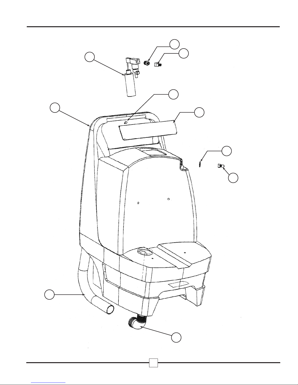
1740215 1 SOLUT ON TANK
2 740100 1 CHEM CAL FEED COMPLETE SEE F GURE 3
3 700236 1 HEX N PPLE 1/2˝X1/4˝
4700313 1 ELBOW STREET 1/4˝ 45*
5 780617 4 SCREW-MACH PH L– 4X1/2˝ SS
6 740235 1 S GN PLATE
7 780214 1 WASHER– 9/16˝X1 1/8˝ SS
8 700111 1 MALE QD 1/4˝
9 740181 1 PVC ELBOW BARB 2˝X2˝MPT
10 740041 1 VAC HOSE/TANK TO VAC 24.5˝
11 705110 2 DRA N VALVE 45* EXT-2˝
12 705102 1 DRA N VALVE 2˝ X 1 1/2˝ MPT
13 740033 1 PVC BARB 2˝ X 2˝ MPT
14 740027 1 CAM LOCK MALE 1-1/4˝ MPT
15 740256 2 RUBBER WASHER 5/16˝X1-3/8˝
16 780213 2 WASHER-3/8˝X1-1/2˝
17 780017 2 BOLT-1/4-20SAE X 1˝ SS
18 & 28 740232 1 PUMPOUT ASSEMBLY W/SW TCH(115V)
18 & 28 740260 1 PUMPOUT ASSEMBLY W/SW TCH(230V)
19 705008 2 VAC CUFF 1-1/4˝ X 1-1/4˝
20 705107 1 DRA N VALVE NUT 1-1/4˝
21 740028 1 CHECK VALVE 1-1/4˝
22 740029 2 PVC BARB 1-1/4˝ X 1-1/4˝ MPT
23 740092 1 VAC HOSE/ AUTO PUMPOUT-9˝
24 740257 1 8˝ DECK L D W/ GASKET
- 740173 GASKET ONLY
- 740174 8˝ DECK L D ONLY
25 740218 1 FLOAT SHUTOFF ELBOW
26 740200 1 FLOAT BALL SHUTOFF
27 702905 3 HOSE CLAMP 2 1/4˝
28 & 18 740232 1 PUMPOUT ASSEMBLY W/SW TCH(115V)
28 & 18 740260 1 PUMPOUT ASSEMBLY W/SW TCH(230V)
29 705105 1 DRA N VALVE NUT 2˝
30 740253 1 PVC 2˝ ELBOW WASTE BAG RET.
31 740036 1 WASTE F LTER BAG
32 740214 1 WASTE TANK
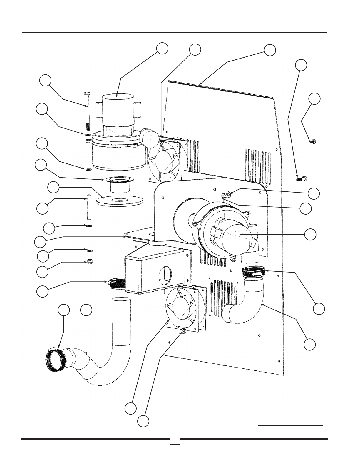
33 740258 1 VAC HOSE/VAC TO MUFFLER 7.5˝ 1200
34 780401 32/35 NUT-NYLOC 1/4˝X20SAE
35 780201 68/80 WASHER-1/4˝
36 740231 1 VACUUM MAN FOLD 2-2 STAGE 1200
37 740226 6/9 VAC SPACER
38 740209 2/3 VAC GASKET
39 740043 2/3 2˝ VAC MOTOR NTAKE FLANGE
40 780016 6/9 BOLT-1/4˝-20SAE X 3 1/2˝
41 724001 1 VAC MOTOR 2-STAGE/093/120V
42 740219 1/2 AX AL FAN 115V
42 740236 1/2 AX AL FAN 230V
43 740203 1 BACK PLATE W/CORD WRAPS
44 780001 18 BOLT-1/4˝-20SAE X 3/4˝
45 780613 12 SCREW-PH L TRUSS 1/4˝-20X 5/8˝
46 724000 1/2 VAC MOTOR 2-STAGE/096/115V
41 & 46 724003 2/3 VAC MOTOR 2-STAGE/196/230V ALL MODELS
TRUCKFORCE®PARTS LIST
7
TRUCKFORCE®
MasterBlend (800) 525-9644
ITEM # PART # QTY DESCRIPTI N N TES
1200/3500

47 780615 4/8 SCREW-PH L/PAN 6-32X1/2˝
48 780413 4/8 NUT-NYLOC 6-32 18.8
49 740208 1 VACUUM MAN FOLD 3-2 STAGE 3500
* 740233 1 CHEM CAL HOLDER/FUNNEL
50 740206 1 SW TCH PLATE (specify model)
51 740193 1 HOUR METER
52 740211 1 SW TCH DPST RED L GHTED
53 740210 3/4 SW TCH DPST GREEN L GHTED
54 780614 3 SCREW-PH L-TRUSS-10-24X3/8˝
55 780411 2 NUT-NYLOC-5/8˝X11SAE
56 780218 4 WASHER-5/8˝X1-1/8˝
57 740212 2 WHEEL 12˝ FOAM
58 740213 2 CASTER 4˝ X 1.25˝
59 700270 2 COUPLER 1/4˝ X 1/4˝ FPT
60 719000 1 PRESSURE GAUGE “U” CLAMP
61 719003 1 PRESSURE GAUGE-1200 PS 1200
61 719002 1 PRESSURE GAUGE-1000 PS 3500
62 780617 4 SCREW-PH L/PAN 10-32X1/2˝
63 780221 4 WASHER-#10SS
64 780410 4 NUT-10-32
65 700101 1 QD 1/4˝ FEMALE
66 780214 1 WASHER-9/16˝X1-1/16˝SS
67 715011 1 UNLOADER – 1200 PS 1200
67 715022 1 REGULATOR-600PS 3500
- 715023 PRESSURE REG. K T/P STON/UCUP/
68 715025 1 PRESSURE REG. BACK PLATE
69 700307 8 ELBOW STREET 3/8˝
70 715024 1 PRESSURE REG. FRONT PLATE
71 721122 1 PULSEHOSE- 3/8˝ MPT X 3/8˝ FPT
72 721023 1 PULSEHOSE- 3/8˝ FPT X 1/4˝ MPT
73 721221 1 PULSEHOSE- 3/8˝ MPT X 1/4˝ FPT
74 740259 2 HOSE 1/2˝ CLEAR 9˝ SOLUT ON/PUMP
75 702902 2 HOSE CLAMP 1/2˝
76,77,78,79 740221 1 FRESH WATER F LTER 1/2˝ BARBS
80 721401 1 1200 PS PUMP 1200
80 720010 500 PS PUMP 3500
81 721402 MOTOR/115VDC/FOR 1200 PS PUMP 1200
81 726001 MOTOR/115V/.5HP/FOR 500 PS PUMP 3500
82 740142 4 MOTOR MOUNT
83 740055 1 HOSE BYPASS TO SOLUT ON TANK
84 700293 1 HEX PLUG 1/4˝
85 740202 1 BOTTOM PLATE/AXEL/H NGE
86 700303 1 ELBOW STREET 1/4˝
87 700350 1 FLARE 1/2˝ X 1/2˝ MPT 90° ELBOW
88 700329 2 TEE MALE BRANCH - 3/8˝
89 700284 1 BUSH NG 3/8˝ x 1/4˝
90 721113 1 POWER PR ME VALVE
91 740195 1 PR ME VALVE HOSE
*NOT SHOWN ON SCHEMATIC
ITEM # PART # QTY DESCRIPTI N N TES
1200/3500
8
TRUCKFORCE®
MasterBlend (800) 525-9644
1
2
3
4
5
6
7
8
9
10
9
TRUCKFORCE®
MasterBlend (800) 525-9644

20 21
22 19 23 24
25
26
11
27
28
29
30
31
32
9
11
12
13
14
18
17
19
16
15
10
TRUCKFORCE®
MasterBlend (800) 525-9644

51
52 53 53 53 53
54
50
44 45
35
49
34
46
38
39
46
47
42
10
27
27
34
34
35
35
37
35
40
41
35
38
48
11
TRUCKFORCE®
MasterBlend (800) 525-9644
Model 3500
Model 3500
12
TRUCKFORCE®
MasterBlend (800) 525-9644
41 42 43
44
45
35
34
46
27
33
42
27
35
37
38
39
35
35
40
36
35
34
27 10
48
Model 1200

74 75
76 75 74
69
77 78 34
71
85
44
91
88
57
44
65
67
68
86
69
69
80
72
59
70
63
89
64
66
62 61 34
58
35
34
60
34
59
56 55
69 73
35 82
81
83
69
79
87
90
69 69
13
TRUCKFORCE®
MasterBlend (800) 525-9644

KIT-A
KIT-B
KIT-C
14
TRUCKFORCE®
MasterBlend (800) 525-9644
1200 PSI Pum
500 PSI Pum
Part #67 – 500 PSI
Pressure Regulator 1200 PSI
Unloader
Valve

15
TRUCKFORCE®
MasterBlend (800) 525-9644

16
TRUCKFORCE®
MasterBlend (800) 525-9644

17
TRUCKFORCE®
TRUCKF RCE® NE YEAR LIMITED WARRANTY
TRUCKFORCE® is warranted to be free of defects in material and workmanship for a period of
twelve (12) months under normal use and service from the date of original purchase when oper-
ated and maintained in accordance with our Operating and Maintenance instructions. This
warranty does not apply to damage or failure caused by improper use, abuse, or neglect. During
the warranty period, we will repair or replace, at our sole option, any part found to be defective
upon our examination, but will not pay shipping costs, labor, or other costs. To obtain warranty
service, write us at MasterBlend, 5285 Fox Street, Denver, CO 80216, or call (800) 525-9644 or
(303) 373-0702. Parts may not be returned without prior permission and must be returned to us
with freight prepaid.
This warranty does not cover normal wear items such as hoses, power cords, filters, gaskets,
valves, quick disconnects and other parts that require replacement in ordinary use.
Replacement parts are warranted only for the remaining period of the original warranty.
This warranty is for the replacement of defective parts or workmanship only. t does not pro-
vide for the replacement of entire units due to defective parts or workmanship.
This warranty does not cover labor or any other charges in connection with the replacement of
defective parts. No local service or repair charges are allowed.
This warranty service is an exclusive remedy and we are not responsible for any consequential
or incidental damages or injury to person or property.
WARRANTY INF RMATI N
SERIAL NUMBER: _________________________________________
DATE F PURCHASE: _____________________________________
PURCHASED FR M: ______________________________________
PLEASE RETURN THE WARRANTY REGISTRATI N CARD
MasterBlend (800) 525-9644
This manual suits for next models
1
Table of contents
Popular Scrubber manuals by other brands

Advance acoustic
Advance acoustic Condor XL 56110000 Instructions for use

ABATEMENT
ABATEMENT PREDATOR PRED750 instruction manual

Kärcher
Kärcher KM 130/300 R LPG Original instructions

Coopers
Coopers 10946 Instructions for use

YANGZI
YANGZI YZ-X7 operating manual

Columbus
Columbus ARA 85 BM 120 operating manual


Tornado
Tornado ECO 500 AW Series Operation & maintenance manual

Superabrasive
Superabrasive LAVINA ELITE Series user manual

Windsor
Windsor chariot iScrub cs20 operating instructions

Nederman
Nederman ORIGINAL 535 Series instruction manual

CleanFreak
CleanFreak CPL DURA-20B Instructions for use - original instructions

Taski
Taski swingo 450E Instructions of use