Tennant EZ Rider User manual

This manual is furnished with each new TENNANT Model EZ Ridert. It provides necessary operating
and preventive maintenance instructions. Read this manual completely and understand the machine
before operating or servicing it.
This machine will provide excellent service. However, the best results will be obtained at minimum
costs if:
DThe machine is operated with reasonable care.
DThe machine is maintained regularly -- per the maintenance instructions provided.
DThe machine is maintained with TENNANT supplied or equivalent parts.
Manual Number -- 330730
Revision: 03
Published: 6--02
Copyright E2000 -- 2002 TENNANT, Printed in U.S.A.
New & Reconditioned Equipment & Parts - www.southeasternequipment.net

CONTENTS
1
EZ Rider 330730 (9--00)
CONTENTS
Page
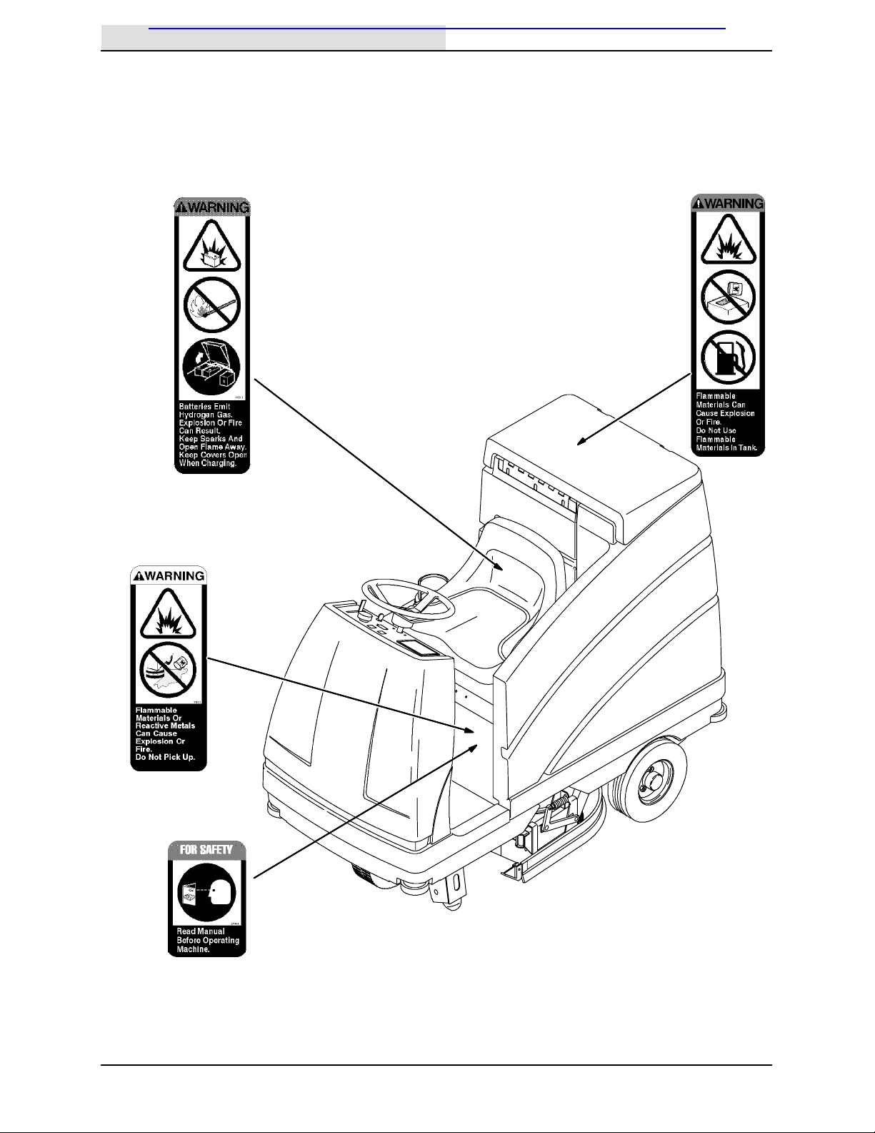
SAFETY PRECAUTIONS 3.................
OPERATION 5............................
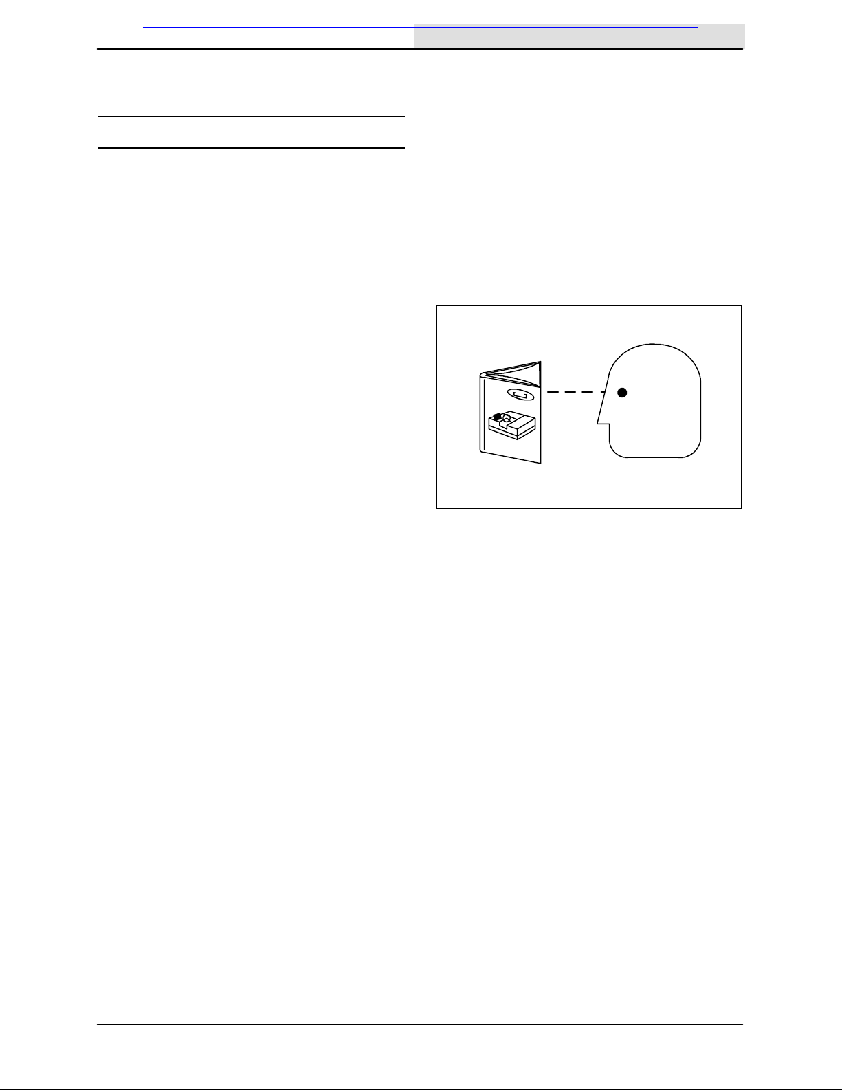
OPERATOR RESPONSIBILITY 5.........
MACHINE COMPONENTS 6.............
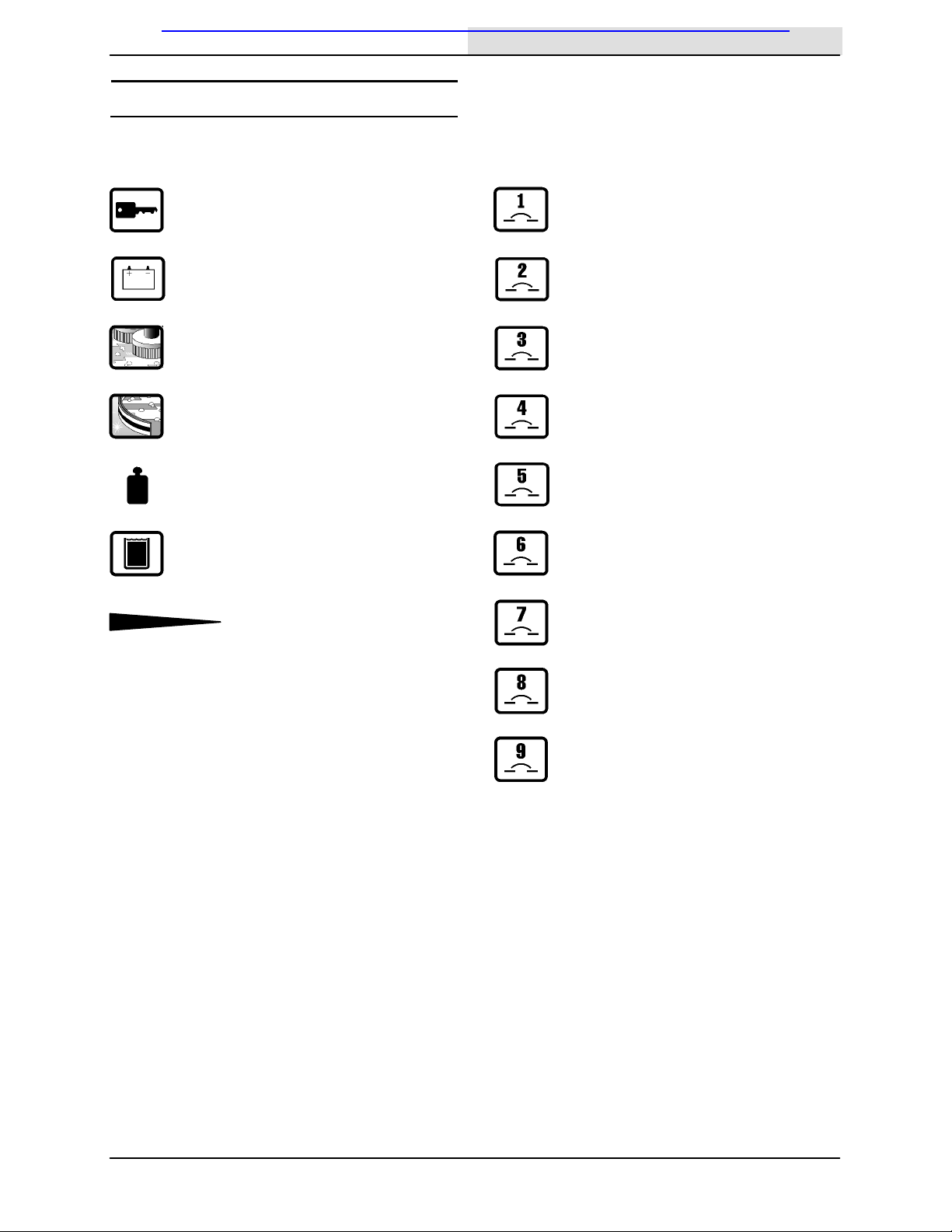
CONTROL PANEL SYMBOLS 7..........
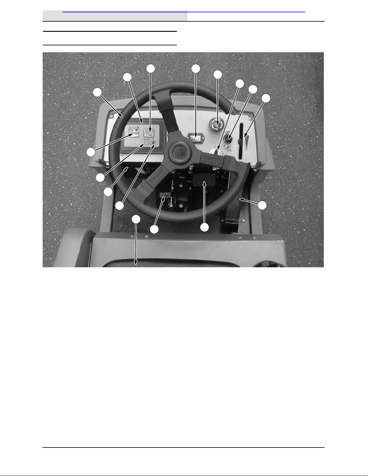
CONTROLS AND INSTRUMENTS 8......
OPERATION OF CONTROLS 9............
BRAKE PEDAL 9......................
PARKING BRAKE PEDAL 9.............
DIRECTIONAL PEDAL 9................
STEERING WHEEL 10.................
ON--OFF KEY SWITCH 11..............
POWER KILL SWITCH 11...............
HOURMETER 11......................
HORN BUTTON 11.....................
SCRUB SWITCH 12....................
REAR SQUEEGEE SWITCH 13.........
RECOVERY TANK FULL INDICATOR 13..
BATTERY DISCHARGE INDICATOR 14..
SOLUTION FLOW LEVER 14............
CIRCUIT BREAKERS 15................
FUSE 15..............................
OPERATOR SEAT 16...................
SEAT SUPPORT ARM 16...............
SQUEEGEE WHEEL CAMS 16..........
SQUEEGEE LEVELING KNOB 17.......
HOW THE MACHINE WORKS 17...........
PRE-OPERATION CHECKLIST 18..........
STARTING THE MACHINE 19..............
FILLING THE TANKS 20...................
SCRUBBING AND BRUSH INFORMATION 22
SCRUBBING 24..........................
DOUBLE SCRUBBING 26..................
OPERATION ON INCLINES 26.............
STOP SCRUBBING 27....................
DRAINING AND CLEANING THE TANKS 28.
STOP THE MACHINE 31..................
POST-OPERATION CHECKLIST 32.........
OPTIONS 33.............................
QUICK MOPt33......................
MACHINE TROUBLESHOOTING 35........
MAINTENANCE 36..........................
MAINTENANCE CHART 37................
LUBRICATION 38.........................
STEERING CASTER PIVOT BEARING 38
REAR SQUEEGEE CASTERS 38........
STEERING GEAR CHAIN 38............
Page
BATTERIES 39...........................
CHARGING THE BATTERIES 41........
SELF--DIAGNOSTIC TEST 43..............
ELECTRIC MOTORS 44...................
SCRUB BRUSHES AND PADS 44..........
DISK BRUSHES 44....................
REPLACING THE DISK BRUSHES
OR PADS 45.....................
CYLINDRICAL BRUSHES 48............
CHECKING AND ADJUSTING
CYLINDRICAL BRUSH
PATTERN 48..................
REPLACING THE CYLINDRICAL
BRUSHES 51....................
SOLUTION SYSTEM 53...................
RECOVERY TANK 53..................
SOLUTION TANK 53...................
REAR SQUEEGEE ASSEMBLY 54..........
REMOVING THE REAR SQUEEGEE
ASSEMBLY 54......................
REPLACING THE REAR SQUEEGEE
ASSEMBLY 55......................
LEVELING THE REAR SQUEEGEE 55...
ADJUSTING REAR SQUEEGEE
BLADE DEFLECTION 56.............
ADJUSTING THE SQUEEGEE GUIDE
ROLLER 57........................
REAR SQUEEGEE BLADES 57............
REPLACING OR ROTATING THE
REAR SQUEEGEE BLADE 57........
REPLACING OR ROTATING THE
FRONT SQUEEGEE BLADE 59.......
SIDE SQUEEGEE BLADES 60.............
REPLACING SIDE SQUEEGEE
BLADES 60.........................
BELTS AND CHAINS 61...................
BRUSH DRIVE BELTS 61...............
STATIC DRAG CHAIN 61...............
STEERING GEAR CHAIN 61............
SKIRTS AND SEALS 62...................
SCRUB HEAD FLOOR SKIRTS 62.......
VACUUM FAN SEAL 62.................
SOLUTION TANK SEAL 63..............
RECOVERY TANK SEAL 63.............
BRAKES AND TIRES 64...................
BRAKES 64...........................
BRAKE ADJUSTMENT: 64...........
TIRES 65............................
New & Reconditioned Equipment & Parts - www.southeasternequipment.net

CONTENTS
EZ Rider 330730 (9--00)
2
Page
PUSHING, TOWING, AND TRANSPORTING
THE MACHINE 66.....................
PUSHING OR TOWING THE
MACHINE 66....................
TRANSPORTING THE MACHINE 66.....
MACHINE JACKING 68....................
STORAGE INFORMATION 69..............
FREEZE PROTECTION 69.................
SPECIFICATIONS 70........................
GENERAL MACHINE
DIMENSIONS/CAPACITIES 70.............
GENERAL MACHINE PERFORMANCE 70......
POWER TYPE 71.........................
TIRES 71................................
MACHINE DIMENSIONS 72...................
INDEX 73...................................
New & Reconditioned Equipment & Parts - www.southeasternequipment.net

SAFETY PRECAUTIONS
3
EZ Rider 330730 (6--02)
SAFETY PRECAUTIONS
The following symbols are used throughout this
manual as indicated in their description:
WARNING: To warn of hazards or
unsafe practices that could result in
severe personal injury or death.
FOR SAFETY: To identify actions that
must be followed for safe operation of
equipment.
This machine is designed solely for scrubbing dirt
and dust in an indoor environment. Tennant does
not recommend using this machine in any other
environment.
The following information signals potentially
dangerous conditions to the operator or
equipment. Read this manual carefully. Know
when these conditions can exist. Locate all safety
devices on the machine. Then, take necessary
steps to train machine operating personnel.
Report machine damage or faulty operation
immediately. Do not use the machine if it is not in
proper operating condition.
WARNING: Batteries emit hydrogen gas.
Explosion or fire can result. Keep
sparks and open flame away. Keep
covers open when charging.
WARNING: Flammable materials can
cause an explosion or fire. Do not use
flammable materials in tank(s).
WARNING: Flammable materials or
reactive metals can cause explosion or
fire. Do not pick up.
FOR SAFETY:
1. Do not operate machine:
-- Unless trained and authorized.
-- Unless operation manual is read and
understood.
-- In flammable or explosive areas unless
designed for use in those areas.
2. Before starting machine:
-- Make sure all safety devices are in
place and operate properly.
-- Check brakes and steering for proper
operation (if so equipped).
3. When starting machine:
-- Keep foot on brake and directional
lever in neutral (if so equipped).
4. When using machine:
-- Use brakes to stop machine (if so
equipped).
-- Go slow on inclines and slippery
surfaces.
-- Use care when reversing machine.
-- Do not carry riders on machine.
-- Always follow safety and traffic rules.
-- Report machine damage or faulty
operation immediately.
-- Follow mixing and handling
instructions on chemical containers.
5. Before leaving or servicing machine:
-- Stop on level surface.
-- Set parking brake.
-- Turn off machine.
6. When servicing machine:
-- Avoid moving parts. Do not wear loose
jackets, shirts, or sleeves when
working on machine.
-- Block machine tires before jacking
machine up.
-- Jack machine up at designated
locations only. Block machine up with
jack stands.
-- Use hoist or jack that will support the
weight of the machine.
-- Wear eye and ear protection when
using pressurized air or water.
-- Disconnect battery connections before
working on machine.
-- Avoid contact with battery acid.
-- Use Tennant supplied or equivalent
replacement parts.
7. When loading/unloading machine
onto/off truck or trailer:
-- Turn off machine.
-- Use truck or trailer that will support
the weight of the machine.
-- Use winch. Do not drive the machine
onto/off the truck or trailer unless the
load height is 380 mm (15 in) or less
from the ground.
-- Set parking brake after machine is
loaded.
-- Block machine tires.
-- Tie machine down to truck or trailer.
New & Reconditioned Equipment & Parts - www.southeasternequipment.net

SAFETY PRECAUTIONS
EZ Rider 330730 (9--00)
4
The safety labels appear on the machine in the
locations indicated. If these or any label becomes
damaged or illegible, install a new label in its
place.
BATTERY CHARGING LABEL -- LOCATED ON
AND UNDERNEATH THE SEAT SUPPORT.
FLAMMABLE SPILLS LABEL --
LOCATED ON THE SEAT SUPPORT.
FOR SAFETY LABEL -- LOCATED ON THE
SEAT SUPPORT.
FLAMMABLE MATERIALS LABEL -- LOCATED
ON THE UNDERSIDE OF THE TANK COVER
AND ON THE LEFT SIDE OF THE OPERATOR
COMPARTMENT.
353451
New & Reconditioned Equipment & Parts - www.southeasternequipment.net

OPERATION
5
EZ Rider 330730 (9--00)
OPERATION
OPERATOR RESPONSIBILITY
-The operator’s responsibility is to take care
of the daily maintenance and checkups of
the machine to keep it in good working
condition. The operator must inform the
service mechanic or supervisor when the
maintenance intervals are required as stated
in the MAINTENANCE section of this
manual.
-Read this manual carefully before operating
this machine.
FOR SAFETY: Do not operate machine,
unless operation manual is read and
understood.
-Check the machine for shipping damage.
Check to make sure machine is complete
per shipping instructions.
-Keep your machine regularly maintained by
following the maintenance information in this
manual. We recommend taking advantage
of a regularly scheduled service contract
from your TENNANT representative.
-Order parts and supplies directly from your
authorized TENNANT representative. Use
the parts manual provided when ordering
parts.
07324
New & Reconditioned Equipment & Parts - www.southeasternequipment.net

OPERATION
EZ Rider 330730 (9--00)
6
MACHINE COMPONENTS
A
A
BCD
CB
E
D
E
H
I
J
J
G
K
F
H
L
G
F
I
K
A. Solution tank
B. Tank Cover
C. Vacuum fan inlet screen
D. Steering wheel
E. Recovery tank
F. Operator seat
G. Batteries
H. Scrub head
I. Side squeegee
J. Rear wheel
K. Rear squeegee
L. Front wheel
New & Reconditioned Equipment & Parts - www.southeasternequipment.net

OPERATION
7
EZ Rider 330730 (9--00)
CONTROL PANEL SYMBOLS
These symbols identify controls and displays on
the machine:
Key switch Circuit breaker #1
Battery charge Circuit breaker #2
Scrubbing Circuit breaker #3
Squeegee Circuit breaker #4
Brush pressure Circuit breaker #5
Recovery tank full Circuit breaker #6
Solution flow Circuit breaker #7
Circuit breaker #8
Circuit breaker #9
New & Reconditioned Equipment & Parts - www.southeasternequipment.net

OPERATION
EZ Rider 330730 (9--00)
8
CONTROLS AND INSTRUMENTS
AG
H
M
P
O
N
B
C D
E
I
F
J
K
L
A. Steering wheel
B. Control panel
C. Rear squeegee switch
D. Hourmeter
E. Power kill switch
F. On/Off key switch
G. Horn button
H. Solution flow lever
I. Directional pedal
J. Brake pedal
K. Parking brake pedal
L. Operator seat
M. Recovery tank full indicator
N. Circuit breaker panel
O. Battery discharge indicator
P. Scrub switch
New & Reconditioned Equipment & Parts - www.southeasternequipment.net

OPERATION
9
EZ Rider 330730 (9--00)
OPERATION OF CONTROLS
BRAKE PEDAL
The brake pedal stops the machine.
Stop: Take your foot off the directional pedal and
allow it return to the Neutral position. Step on the
brake pedal.
PARKING BRAKE PEDAL
The parking brake pedal sets the front wheel
brake.
Set: Press the brake pedal down as far as
possible with the right foot, then press on the
parking brake pedal with the toe of your left foot to
lock the parking brake pedal in place.
FOR SAFETY: Before leaving or
servicing machine, stop on level
surface, set parking brake, turn off
machine, and remove key.
Release: Press the brake pedal to unlock the
parking brake pedal.
DIRECTIONAL PEDAL
The directional pedal controls direction of travel
and the propelling speed of the machine. You
change the speed of the machine with the
pressure of your foot; the harder you press the
faster the machine travels.
When the machine is moving forward and the
directional pedal is reversed, the machine will
coast for a short distance before changing
direction. Use the brake pedal to stop the
machine.
New & Reconditioned Equipment & Parts - www.southeasternequipment.net

OPERATION
EZ Rider 330730 (9--00)
10
Forward: Press the top of the directional pedal
with the upper part of your foot.
NOTE: The machine will not travel unless the
operator is sitting in the operator’s seat.
Reverse: Press the bottom of the directional
pedal with the heel of your foot.
When the directional pedal is placed into the
reverse position, the rear squeegee will
automatically raise. After a short delay, the
vacuum will stop.
Neutral: Take your foot off the directional pedal
and it will return to the neutral position.
When the directional pedal returns to the neutral
position, the scrub brushes will stop and after a
short delay, the scrub head will raise.
STEERING WHEEL
The steering wheel controls the machine’s
direction of travel.
Left: Turn the steering wheel to the left.
Right: Turn the steering wheel to the right.
New & Reconditioned Equipment & Parts - www.southeasternequipment.net

OPERATION
11
EZ Rider 330730 (9--00)
ON--OFF KEY SWITCH
The on--off key switch controls the machine’s
power with a key.
FOR SAFETY: When starting machine,
keep foot on brake and directional pedal
in neutral.
On: Turn the key all the way clockwise and
release it to the on position.
Off: Turn the key all the way counterclockwise
until it clicks into the off position.
POWER KILL SWITCH
The power kill switch halts all power to the
machine.
Stop machine power: Press the power kill switch.
Restart machine power: Turn off the machine
with the on/off switch. Turn the power kill switch to
the right to release the switch. Turn on the
machine with the on/off key switch.
HOURMETER
The hourmeter records the number of hours the
machine has been operated. Check the hourmeter
regularly; this information is used to determine
when to perform routine machine maintenance.
HORN BUTTON
The horn button operates the horn.
Sound: Press the button.
New & Reconditioned Equipment & Parts - www.southeasternequipment.net

OPERATION
EZ Rider 330730 (12--00)
12
SCRUB SWITCH
The scrub switch controls the scrub head, scrub
brushes, squeegee, and vacuum fan. The scrub
switch is also used to set the scrub brush
pressure.
Start scrubbing: Press the scrub switch.The
pressure indicator light will illuminate, the
squeegee will lower, and the vacuum fan will start.
The scrubbing system and solution flow will start
when the directional pedal is pressed and the
machine begins to move forward.
Stop scrubbing: Press the scrub switch.The
pressure indicator light will go out. The scrub
brushes will stop, the scrub head will raise, and
the solution flow will stop. After a short delay, the
rear squeegee will automatically raise. After
another delay, the vacuum will stop.
The brush down pressure indicators display the
pressure selection. The brush pressure indicator
has three positions. Brush pressure increases as
the indicator light moves to the right across the
display. Travel speed and floor conditions will
affect the scrubbing performance. Under normal
conditions, the brush pressure should be set in
one of the minimum settings. Set the brush
pressure in the maximum setting to scrub a
heavily soiled floor.
Change brush pressure: Press and hold the
scrub switch. The pressure indicator light will
cycle through the three brush pressure settings.
When the switch is pressed and held, the brush
pressure will increase until it reaches the
maximum setting. The pressure will then return to
the minimum setting. Release the scrub switch
when the desired setting is indicated on the
display.
NOTE: When the machine power is turned off, the
brush pressure will remain in the last setting used.
New & Reconditioned Equipment & Parts - www.southeasternequipment.net

OPERATION
13
EZ Rider 330730 (9--00)
REAR SQUEEGEE SWITCH
The rear squeegee switch controls the vacuum
fan and the position of the rear squeegee. The
rear squeegee can be operated separately from
the scrub brushes for the purpose of picking-up
excess water without scrubbing, or double
scrubbing without water pick up
Lower squeegee and start the vacuum fan: Press
the rear squeegee switch. The indicator light
above the switch will illuminate.
Raise squeegee and stop the vacuum fan: Press
the squeegee switch. The indicator light above the
switch will go off. There will be a slight delay
before the vacuum shuts off.
NOTE: The rear squeegee lowers and the
scrubbing vacuum starts automatically, when the
scrubbing operations start.
NOTE: The rear squeegee will raise and the
scrubbing vacuum will shut off after a short delay
when the machine travels in reverse.
NOTE: The rear squeegee will raise and the
scrubbing vacuum fan will shut off after a short
delay when the scrubbing operations are shut off.
RECOVERY TANK FULL INDICATOR
The recovery tank full indicator light will illuminate
when the recovery tank is full.
NOTE: When the indicator illuminates,all
scrubbing functions will shut off automatically.
New & Reconditioned Equipment & Parts - www.southeasternequipment.net

OPERATION
EZ Rider 330730 (9--00)
14
BATTERY DISCHARGE INDICATOR
The battery discharge indicator displays the
charge level of the batteries while the machine is
operating.
When the batteries are fully charged, all four
indicator lights are lit. As the batteries discharge,
the indicator lights will go out from right to left.
The batteries should be recharged when the
indicator on the left flashes. When the indicator
flashes, all scrubbing functions will shut off
automatically. Drive the machine to the battery
charging area and charge the batteries
immediately after the battery discharge indicator
begins to flash.
NOTE: The battery discharge indicator will not
stop flashing until the batteries have been fully
charged.
NOTE: Do not charge the batteries more often
than is necessary to prolong the life of the
batteries. Do not charge the batteries with a “top
off” charge if there is enough remaining charge in
the batteries for the next machine use. Discharge
the batteries to a 20% level, when the battery
discharge indicator segments shut off, before fully
charging the batteries. Do not allow the batteries
to become completely discharged as this will also
damage the batteries. See BATTERIES in the
MAINTENANCE section.
SOLUTION FLOW LEVER
The solution flow lever controls the amount of
solution that flows to the floor while scrubbing.
Increase solution flow: Push the lever forward.
Decrease solution flow: Pull the lever backward.
NOTE: The machine is equipped with a solenoid
valve that automatically stops the solution flow
when the directional pedal is in the neutral
position or when the scrub head is raised.
New & Reconditioned Equipment & Parts - www.southeasternequipment.net

OPERATION
15
EZ Rider 330730 (9--00)
CIRCUIT BREAKERS
Circuit breakers are resetable electrical circuit
protection devices designed to stop the flow of
current in the event of a circuit overload. Once a
circuit breaker is tripped, reset it manually by
pressing the reset button after the breaker has
cooled down.
If the overload that caused the circuit breaker to
trip is still present, the circuit breaker will continue
to stop current flow until the problem is corrected.
The circuit breakers are located on the operator
console.
The chart below shows the circuit breakers and
the electrical components they protect.
Circuit
Breaker Rating Circuit Protected
CB1 5A Machine power
CB2 10 A Lights
CB3 10 A Horn
CB4 10 A Back up alarm
CB5 10 A Control panel
CB6 20 A Vacuum fan
CB7 25 A Left brush motor
CB8 25 A Right brush motor
FUSE
The fuse is a one-time protection device designed
to stop the flow of current in the event of a circuit
overload.
NOTE: Always replace the fuse with a fuse of the
same amperage.
The fuse is located behind the operator console.
Access the fuse by lowering the operator console.
Fuse Rating Circuit Protected
FU-1 40 A Propelling
New & Reconditioned Equipment & Parts - www.southeasternequipment.net

OPERATION
EZ Rider 330730 (9--00)
16
OPERATOR SEAT
The operator seat is designed to be adjusted
forward and backward.
Adjust: Move the lever toward the center of the
seat, slide the seat backward or forward to the
desired position, and release the lever.
NOTE: A seat switch is located under the
operator seat. If there is no weight on the operator
seat, the machine WILL NOT propel in any
direction.
SEAT SUPPORT ARM
The seat support arm holds the seat up to allow
access to the batteries. The support arm
automatically engages when the seat is lifted all
the way up. Lower the seat support by slightly
raising it while pushing the seat support arm
inward.
SQUEEGEE WHEEL CAMS
The squeegee wheel cams adjust the squeegee
deflection along the entire length of the squeegee.
There are wheel cams at either end of the
squeegee.
Increase deflection: Turn the cams
counter-clockwise.
Decrease deflection: Turn the cams clockwise.
New & Reconditioned Equipment & Parts - www.southeasternequipment.net

OPERATION
17
EZ Rider 330730 (9--00)
SQUEEGEE LEVELING KNOB
The squeegee leveling knob adjusts the deflection
at the ends of the squeegee.
The squeegee leveling knob is located directly
behind the squeegee suction hose. DO NOT
disconnect the suction hose from the squeegee
frame when leveling the squeegee.
Increase end deflection: Turn the squeegee
leveling knob counter-clockwise to increase the
deflection at the end of the squeegees.
Decrease end deflection: Turn the squeegee
leveling knob clockwise to decrease the deflection
at the end of the squeegees.
HOW THE MACHINE WORKS
The following machine components work together
to effectively clean dirty floors: solution tank,
scrub brushes, squeegee, vacuum fan, and
recovery tank.
Water and detergent from the solution tank flow to
the floor through a solution valve. The brushes
use the detergent and water solution to scrub the
floor clean. As the machine propels forward, the
squeegee wipes the dirty solution from the floor.
The suction created by the vacuum fan then
draws the dirty solution from the squeegee into
the recovery tank.
The steering wheel controls the direction of
machine travel.The directional pedal controls the
speed and direction of the machine. The brake
pedal slows and stops the machine.
The two available 700 mm (28 in) scrub head
types use disk or cylindrical brushes.
NOTE: The amount and type of soilage play an
important role in determining the type of brushes
to be used. For specific recommendations,
contact your Tennant representative.
When finished scrubbing, clean the recovery tank.
New & Reconditioned Equipment & Parts - www.southeasternequipment.net

OPERATION
EZ Rider 330730 (9--00)
18
PRE-OPERATION CHECKLIST
Perform the following steps before operating the
machine:
-Check under the machine for leaks.
-Check the brakes and steering for proper
operation.
-Check the squeegees for wear and damage.
New & Reconditioned Equipment & Parts - www.southeasternequipment.net
Table of contents
Other Tennant Scrubber manuals

Tennant
Tennant 7300 User manual

Tennant
Tennant T20 LPG User manual

Tennant
Tennant T2 User manual

Tennant
Tennant T7 User manual

Tennant
Tennant Nobles WB-20B Product manual

Tennant
Tennant M17 Series Training manual

Tennant
Tennant CS16 User manual

Tennant
Tennant 7100 User manual

Tennant
Tennant t500 User manual

Tennant
Tennant T5 User manual

Tennant
Tennant T681 User manual

Tennant
Tennant T191 User manual

Tennant
Tennant 5700XP User manual

Tennant
Tennant T7AMR User manual

Tennant
Tennant T20 Gas User manual

Tennant
Tennant 612950 Product manual

Tennant
Tennant 255 Series II User manual

Tennant
Tennant 7100 User manual

Tennant
Tennant M30 Operating and installation instructions

Tennant
Tennant 800D User manual