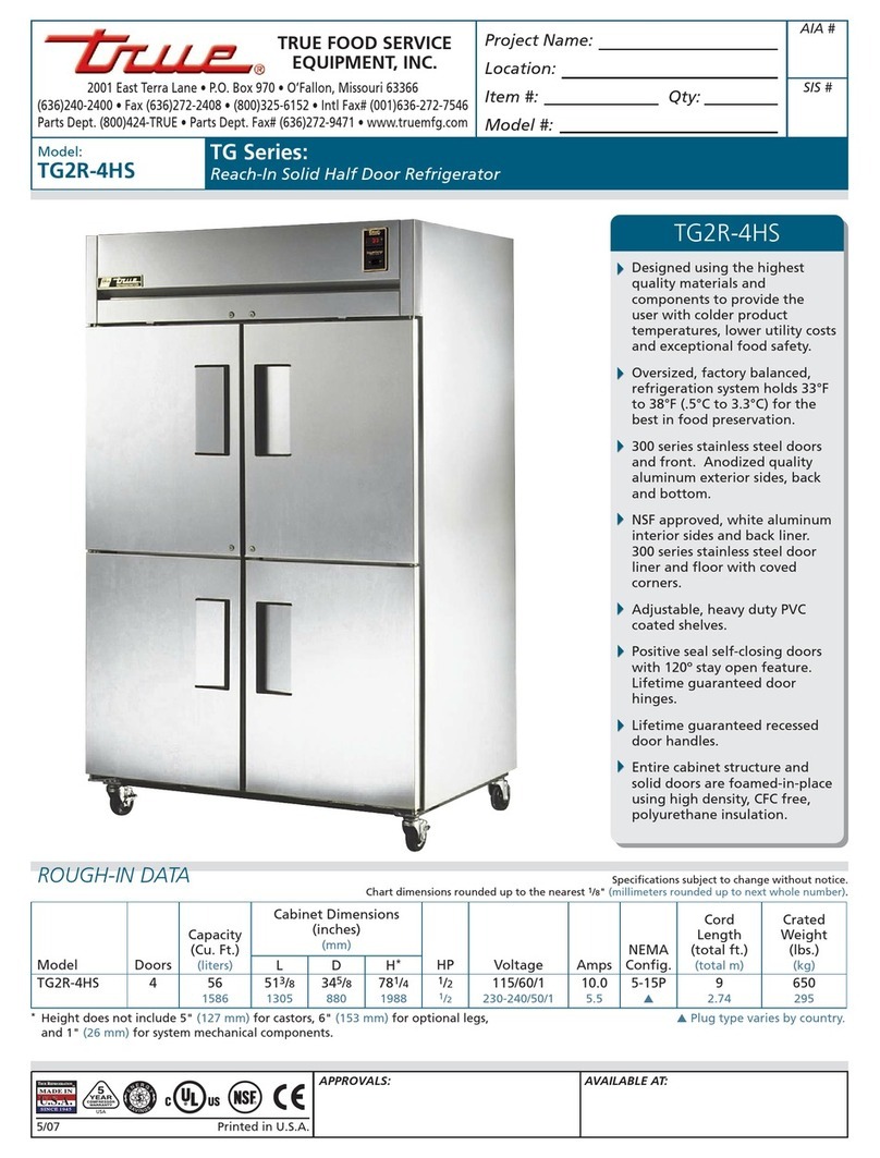
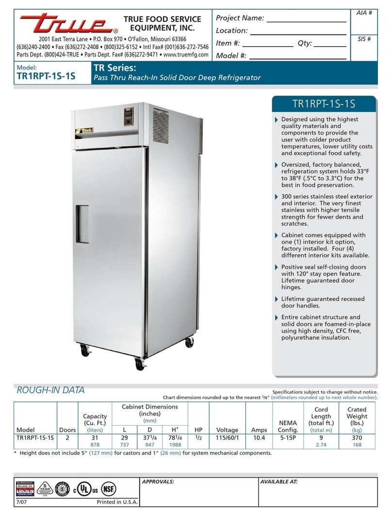
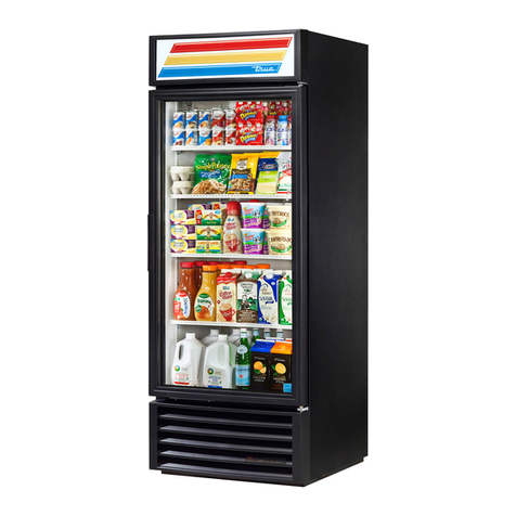
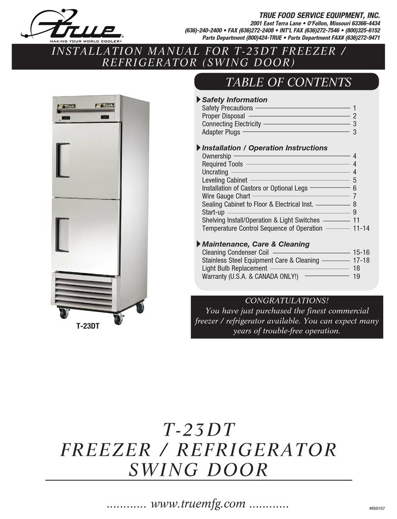
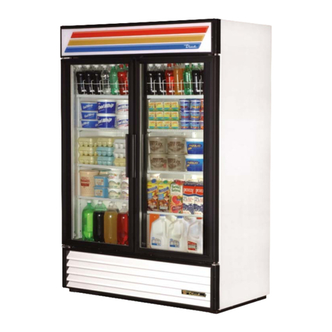
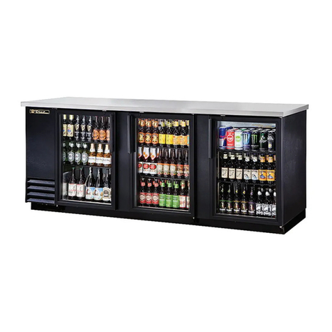
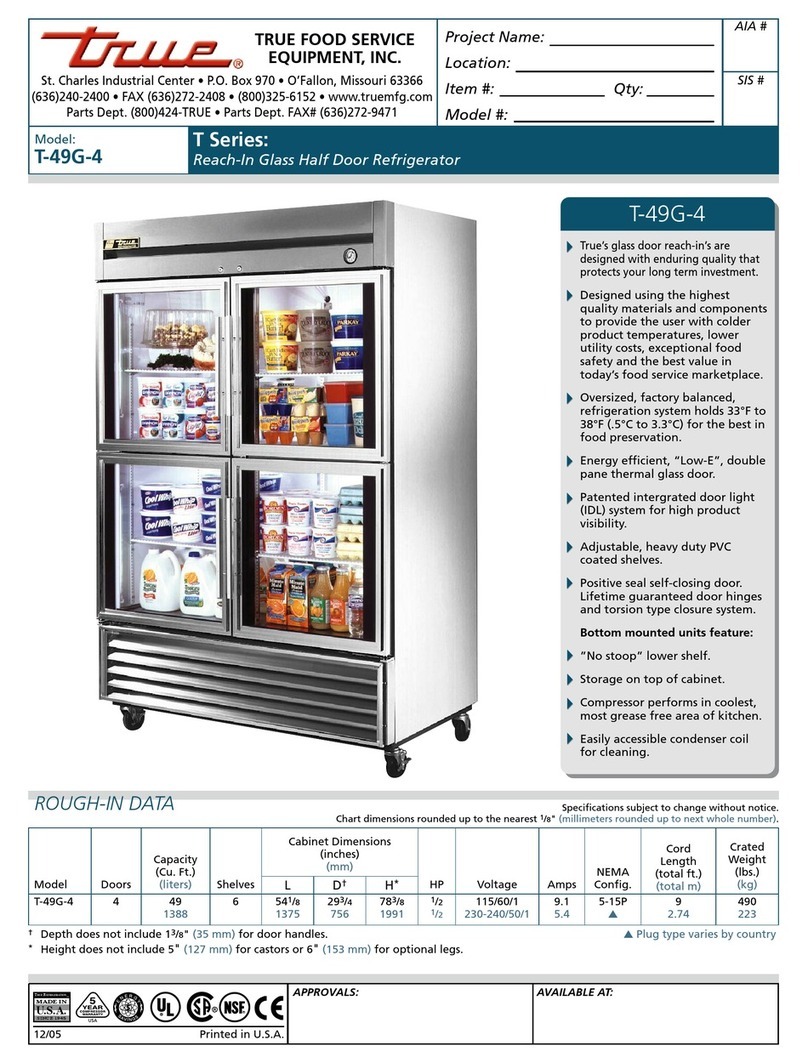
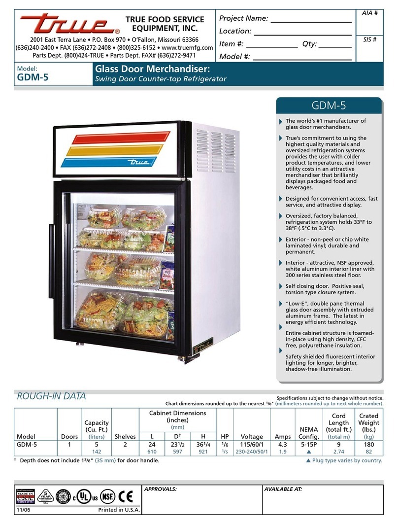
True T-23 User manual

............ www.truemfg.com ............
TABLE OF CONTENTS
Safety Information
Safety Precautions 1
TSD Do’s and Don’ts 2
Proper Disposal 3
Connecting Electricity 4
Adapter Plugs 4
Installation / Operation Instructions
Ownership 5
Required Tools 5
Uncrating 5
Leveling Cabinet 6
Installation of Castors or Optional Legs 7
Installing Optional Castors on a T-12FG 8
Slide Door Operation Instructions 9
Wire Gauge Chart 10
Sealing Cabinet to Floor & Electrical Inst. 11
Start-up 12
LAE Temp Control 13-21
Shelving Install/Operation & Light Switches 22
Grasslin Defrost Timer (Freezer Units Only) 23
Temperature Control High Altituded Adjustment 24
Field Troubleshooting (Freezer Units Only) 25-26
Light Cover Install for T-12FG 27
Maintenance, Care & Cleaning
Cleaning Condenser Coil 28-29
Stainless Steel Equipment Care & Cleaning 30-31
Light Bulb Replacement 31
Warranty (U.S.A. & CANADA ONLY!) 32
INSTALLATION MANUAL FOR T-SERIES FREEZER /
REFRIGERATOR (SWING AND SLIDE DOOR)
T-SERIES
FREEZER / REFRIGERATOR SWING
& SLIDE DOOR
TRUE FOOD SERVICE EQUIPMENT, INC.
2001 East Terra Lane • O’Fallon, Missouri 63366-4434
(636)-240-2400 • FAX (636)272-2408 • INT’L FAX (636)272-7546 • (800)325-6152
Parts Department (800)424-TRUE • Parts Department FAX# (636)272-9471
CONGRATULATIONS!
You have just purchased the finest commercial
freezer / refrigerator available. You can expect many
years of trouble-free operation.
#897001 • RD • 4/13
*Spanish, German, French, Dutch, and Arabic versions included.
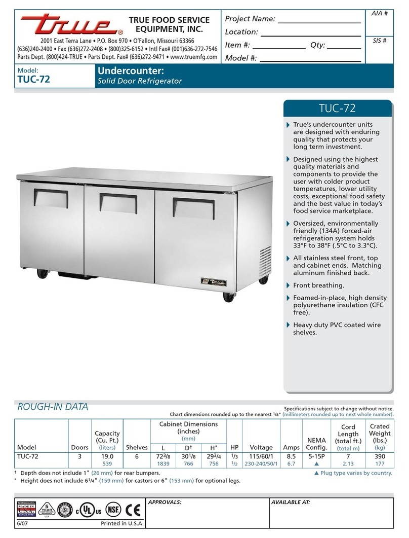
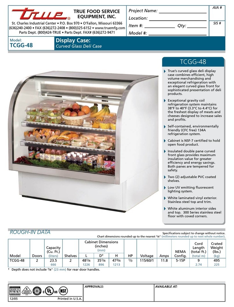
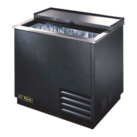
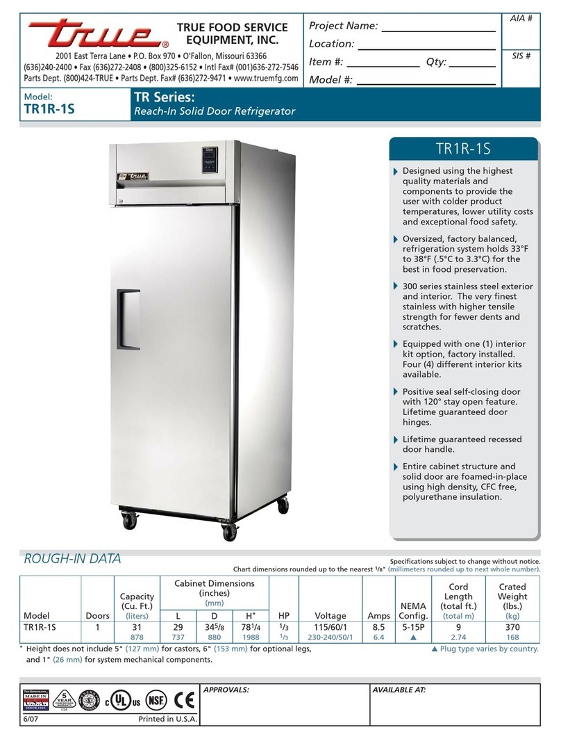
T-23
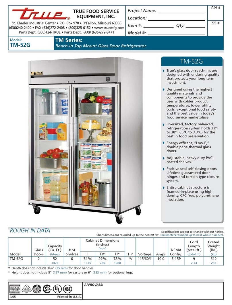
TSD-69
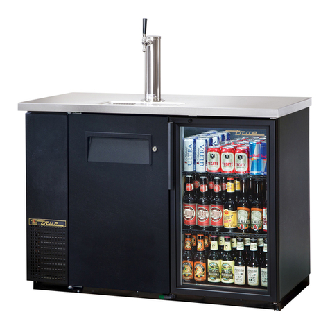
T-49
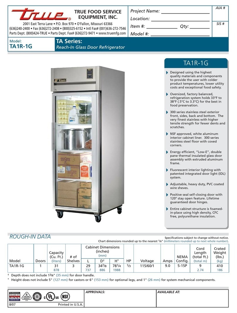
TSD-47G

............ www.truemfg.com ............
True Food Service Equipment, Inc.

............ www.truemfg.com ............
True Food Service Equipment, Inc.
11
............ www.truemfg.com ............
SAFETY INFORMATION
11
NOTE
We strongly recommend that any servicing be performed by
a qualified individual.
Danger
Danger
Caution
Caution
Caution
Caution
WARNING!
Use this appliance for its intended purpose as described in this Owner Manual.
TO LOCATE REFRIGERANT TYPE, SEE SERIAL LABEL INSIDE CABINET.
This cabinet may contain fluorinated greenhouse gas covered by the Kyoto Protocol (please refer
to cabinet’s inner label for type and volume, GWP of 134a= 1,300. R404a= 3,800).
For Hydrocarbon Refrigeration Only (R-290) See Below:
How to Maintain Your TRUE Unit to Receive the Most Efficient and
Successful Operation
You have selected one of the finest commercial refrigeration units made. It is manufactured under strict quality controls
with only the best quality materials available. Your TRUE cooler when properly maintained will give you many years of
trouble-free service.
SAFETY PRECAUTIONS
When using electrical appliances, basic safety precautions should be followed, including the following:

............ www.truemfg.com ............
True Food Service Equipment, Inc.
2 2

............ www.truemfg.com ............
True Food Service Equipment, Inc.
33
SAFETY INFORMATION
PROPER DISPOSAL OF THE FREEZER /
REFRIGERATOR
DANGER!
RISK OF CHILD ENTRAPMENT
USE OF EXTENSION CORDS
NEVER USE AN EXTENSION CORD! TRUE will not warranty any refrigerator that has been connected to an extension cord.
Before You Throw Away Your Old Refrigerator or
Freezer:
Refrigerant Disposal
REPLACEMENT PARTS

............ www.truemfg.com ............
True Food Service Equipment, Inc.
4 4
WARNING!
SAFETY INFORMATION
WIRING CONVERSION
At Receptacle Box
1.
2.
3.
4.
At Breaker Panel
1.
2.
3.
4.
5.
6.
HOW TO CONNECT ELECTRICITY
Do not, under any circumstances, cut or remove the ground prong from the power cord.
For personal safety, this appliance must be properly grounded.
USE OF ADAPTER PLUGS
NEVER USE AN ADAPTER PLUG! Because of potential safety hazards under certain conditions, we strongly recommend
against the use of an adapter plug.
T-72F WIRING CHANGES (110V Application Only)
Previous design: 4 prong plug NEMA 14-20R - 4 wire circuit (see image 1).
Current design: 3 prong plug NEMA 5-20R - 3 wire circuit (see image 2).
(North America Use Only!)
1 2
NOTE: It is the customer’s responsibility to make sure receptacle wiring
meets all local electrical codes. TRUE recommends hiring a licensed qualified
electrician to make this change.
............ www.truemfg.com ............
True Food Service Equipment, Inc.
55
INSTALLATION / OPERATION INSTRUCTIONS
TRUE
TRUE
TRUE is not responsible for damage incurred during
shipment.
OWNERSHIP
REQUIRED TOOLS
NOTE
Units with a solar thermometer will experience a 15 second delay
after exposed to light before they read the proper temperature.
A.
B.
C.
NOTE
Keys for coolers with door locks are located in warranty packets.
UNCRATING
INSTALLATION / OPERATION INSTRUCTIONS
1 2 3
456

............ www.truemfg.com ............
True Food Service Equipment, Inc.
6 6
INSTALLATION / OPERATION INSTRUCTIONS
P
A.
WARNING
Warranty is void if ventilation is insufficient.
B.
C.
D.
E.
F.
WARNING
Cabinet warranties are void if OEM power cord is tampered
with. TRUE will not warranty any units that are connected to
an extension cord.
LEVELING
LOCATING
REMOTE UNITS (This section applies to remotes only!)
If you have any questions regarding this section, please
call TRUE at 1-(800)-325-6152.
A.
B.
C.
D.
E.
F.
Removing skid from bottom
of cabinet.
A B
C

............ www.truemfg.com ............
True Food Service Equipment, Inc.
77
INSTALLATION / OPERATION INSTRUCTIONS
Rail End
Lower Rail
Assembly
Snug Fit
Here
Leveling Shim
CastorLeg
Bearing
Race
Lower Rail Assembly
Snug Fit
Here
Rail End
Thread castor into the underside of
cabinet frame rail.
Thread leg into cabinet bottom
frame rail.
The end of the leg is adjustable
to easy leveling.
Use the tool provided to tighten
the castor into place.
For leveling, insert the shim
between the castor and frame rail.
1234
5
INSTALLATION OF CASTORS OR OPTIONAL LEGS
Important Safeguard for installation of leg/castor (Images 1-5 demonstrate procedure)
Securing Castors and Legs
Unit leveling
A.
B.
C.
D.
CAUTION
To avoid damage to lower rail assembly, slowly raise unit to
upright position.
NOTE
Open holes located on the cross members of the frame rail
should be plugged before unit is in use.

............ www.truemfg.com ............
True Food Service Equipment, Inc.
8 8
Final Location
A.
B.
C.
D.
NOTE
Two out of the four castors are designated with an “F” for front.
These are provided with hand-brakes. Position these castors in
FRONT of the unit.
E.
F.
WARNING
Unit may tip forward if procedure “F” is not
strictly followed.
G.
H.
I.
WARNING
Warranty is VOID if ventilation is insufficient.
J.
WARNING
Cabinet warranties are void if OEM power cord is tampered with.
TRUE will not warranty any units that are connected to an exten-
sion cord.
K.
INSTALLING OPTIONAL CASTORS ON A T-12FG
INSTALLATION / OPERATION INSTRUCTIONS
POSITIONING OF THE
CASTOR IS CRITICAL.
ORIENT THE CASTOR IN
THE FORWARD POSITION
AS SHOWN

............ www.truemfg.com ............
True Food Service Equipment, Inc.
99
INSTALLATION / OPERATION INSTRUCTIONS
STEP 2
TO ADJUST SLIDE DOOR
P-Clip keeps cord
in-place (prevents
cord damage).
(Three Door Units ONLY)
STEP 6
STEP 1
STEP 7
CENTER DOOR
(Three Door Units ONLY)
STEP 1
STEP 2
Two Door Units:
Three Door Units:
(Two Door Units ONLY)
CENTERED DOOR
(Three Door Units ONLY)
TRUE Logo
STEP 5
STEP 4
STEP 3
(TWO DOOR UNITS SKIP TO STEP 6)
TRUE Logo
Gasket fasten to door bottom assures door will
remain in track when unit is placed on uneven
surface.
Door Cord
Knot
SLIDE DOORS
1
46
7
9
10
8
5
2
3

............ www.truemfg.com ............
True Food Service Equipment, Inc.
10 10
INSTALLATION / OPERATION INSTRUCTIONS
Wire Gauge for 2% Voltage Drop in Supply Circuits
115 Volt Distance In Feet To Center of Load
Amps 20 30 40 50 60 70 80 90 100 120 140 160
2 14 14 14 14 14 14 14 14 14 14 14 14
3 14 14 14 14 14 14 14 14 14 14 14 12
4 14 14 14 14 14 14 14 14 14 12 12 12
5 14 14 14 14 14 14 14 12 12 12 10 10
6 14 14 14 14 14 14 12 12 12 10 10 10
7 14 14 14 14 14 12 12 12 10 10 10 8
8 14 14 14 14 12 12 12 10 10 10 8 8
9 14 14 14 12 12 12 10 10 10 8 8 8
10 14 14 14 12 12 10 10 10 10 8 8 8
12 14 14 12 12 10 10 10 8 8 8 8 6
14 14 14 12 10 10 10 8 8 8 6 6 6
16 14 12 12 10 10 8 8 8 8 6 6 6
18 14 12 10 10 8 8 8 8 8 8 8 5
20 14 12 10 10 8 8 8 6 6 6 5 5
25 12 10 10 8 8 6 6 6 6 5 4 4
30 12 10 8 8 6 6 6 6 5 4 4 3
35 10 10 8 6 6 6 5 5 4 4 3 2
40 10 8 8 6 6 5 5 4 4 3 2 2
45 10 8 6 6 6 5 4 4 3 3 2 1
50 10 8 6 6 5 4 4 3 3 2 1 1
Wire Gauge for 2% Voltage Drop in Supply Circuits
230 Volts Distance In Feet To Center of Load
Amps 20 30 40 50 60 70 80 90 100 120 140 160
5 14 14 14 14 14 14 14 14 14 14 14 14
6 14 14 14 14 14 14 14 14 14 14 14 12
7 14 14 14 14 14 14 14 14 14 14 12 12
8 14 14 14 14 14 14 14 14 14 12 12 12
9 14 14 14 14 14 14 14 14 12 12 12 10
10 14 14 14 14 14 14 14 12 12 12 10 10
12 14 14 14 14 14 14 12 12 12 10 10 10
14 14 14 14 14 14 12 12 12 10 10 10 8
16 14 14 14 14 12 12 12 10 10 10 8 8
18 14 14 14 12 12 12 10 10 10 8 8 8
20 14 14 14 12 10 10 10 10 10 8 8 8
25 14 14 12 12 10 10 10 10 8 8 6 6
30 14 12 12 10 10 10 8 8 8 6 6 6
35 14 12 10 10 10 8 8 8 8 6 6 5
40 14 12 10 10 8 8 8 6 6 6 5 5
50 12 10 10 8 6 6 6 6 6 5 4 4
60 12 10 8 6 6 6 6 6 5 4 4 3
70 10 10 8 6 6 6 5 5 4 4 2 2
80 10 8 8 6 6 5 5 4 4 3 2 2
90 10 8 6 6 5 5 4 4 3 3 1 1
100 10 8 6 6 5 4 4 3 3 2 1 1
CONDUCTORS AND CIRCUITS

............ www.truemfg.com ............
True Food Service Equipment, Inc.
11 11
INSTALLATION / OPERATION INSTRUCTIONS
A.
B.
TRUE
WARNING
Compressor warranties are void if compressor burns out
due to low voltage.
WARNING
Power supply cord ground should not be removed!
WARNING
Do not use electrical appliances inside the food storage
compartments of the appliances unless they are of the
type recommended by the manufacturer.
NOTE
To reference wiring diagram - Remove front louvered grill,
wiring diagram is positioned on the inside cabinet wall.
ELECTRICAL INSTRUCTIONS
Step 1 - Position Cabinet
Step 2 - Level Cabinet
A
B
C
Step 3
Step 4
Step 5
Step 6
Step 7
Step 8
NOTE
Asphalt floors are very susceptible to chemical attack. A
layer of tape on the floor prior to applyingthe sealant will
protect the floor.
NSF Approved Sealants:
SEALING CABINET TO FLOOR

............ www.truemfg.com ............
True Food Service Equipment, Inc.
12 12
INSTALLATION / OPERATION INSTRUCTIONS
A.
B.
C.
D.
NOTE
If the cooler is disconnected or shut off, wait five minutes
before starting again.
RECOMMENDATION
Before loading product we recommend you run your TRUE
unit empty for two to three days. This allows you to be sure
electrical wiring and installation are correct and no shipping
damage has occurred. Remember, our factory warranty
does not cover product loss!
REPLACEMENT PARTS
TRUE maintains a record of the cabinet serial number
for your cooler. If at any time during the life of your
cooler, a part is needed, you may obtain this part by
furnishing the model number and serial number to the
company from whom you purchased the cooler. Call
Toll-Free: (800)-424-TRUE (Direct to Parts Department).
(800)-325-6152 (U.S.A. & Canada only) or call:
(636)-240-2400.
STARTUP
WARNING
COMPRESSOR BAND MUST BE REMOVED BEFORE UNIT IS
CONNECTED TO POWER SUPPLY.
FREEZERS ONLY! (COMPRESSOR BAND REMOVAL)
PLEASE CHECK YOUR COMPRESSOR. IF THERE IS A SHIPPING BAND, PLEASE REMOVE.
Cutting band that is around compressor

............ www.truemfg.com ............
True Food Service Equipment, Inc.
13 13
IF YOUR CABINET IS BUILT WITH THIS
TEMPERATURE CONTROL, PLEASE SEE THE
FOLLOWING INSTRUCTIONS.

............ www.truemfg.com ............
True Food Service Equipment, Inc.
14 14
LAE CONTROL
SEQUENCE OF OPERATION
1. Cabinet is plugged in.
a. Display will illuminate.
b. Interior light will illuminate on glass door models only. (If lights do not come on please see
instructions on following page(s).) Solid door cabinet lights are controlled by door switch.
2. After the LAE control preprogrammed time delay of 3 minutes, the compressor and evaporator fan(s) will start if
the control is calling for cooling.
a. Control may be already pre-programmed from the factory so at the start of every compressor cycle or
during a defrost cycle, the condenser fan(s) will reverse for 30 seconds to blow dirt off the condensing
coil.
3. The LAE control will cycle the compressor but may also cycle evaporator fan(s) on and off determined by the
Set-Point and Differential temperatures. (If the Set-Point needs to be changed due to conditions please see
instructions on the following page(s).)
a. The Set-Point is the preprogrammed temperature which shuts off the compressor.
b. The Differential is the preprogrammed temperature that is added to the Set-Point temperature that will
start the compressor.
Example: If the Set-Point is -9°F/-23°C and the Differential is 10°F/5°C
(Set-Point) -9°F + 10 (Differential) = 1°F
Or
(Set-Point) -23°C + 5 (Differential) = -18°C
The compressor and evaporator fan(s) will cycle off -9°F/-23°C
and back on at 1°F/-18°C
4. The LAE control may be preprogrammed to initiate defrost by interval or at specic times of day. (If additional
Defrost Intervals or Cycles are needed or a Manual Defrost is required due to conditions please see instruc-
tions on the following page(s).)
a. At this time the “dEF” will appear on the display and compressor will turn off until a preprogrammed
temperature or duration is reached. During this time for freezers only, evaporator fan(s) will also
turn off and the coil heater and drain tube heaters will also be energized.
b. After the preprogrammed temperature or duration for defrost has been reached there may be a short
delay for both the compressor and evaporator fans to restart. At this time “dEF” may still appear
on the display for a short time.
True Manufacturing recommends that ONLY the Set-Point and/or
Defrost Interval may be adjusted due to certain conditions.
This sequence is NOT model specific.
If you have any questions, please contact the Technical Service Department.
Phone: 800-325-6152 • Email: service@truemfg.com

............ www.truemfg.com ............
True Food Service Equipment, Inc.
15 15
LOCKING & UNLOCKING LAE CONTROLLER
WHY:
LOCKING OF CONTROL IS NECESSARY TO PREVENT
CHANGES TO PROGRAM THAT MAY AFFECT CABINET
OPERATION
HOW:
A.
B.
C.
1
2
5
LAE Electronic Control
Info/Set Point
Button
Manual Defrost/
Down Button
Manual Activation/
Up Button
Stand-By
Button
3Image 3:
If “no” appears
on screen,
the controller
is unlocked.
4Image 4:
If “yes” appears
on screen,
the controller
is locked.
Compressor
Running
Activation of 2nd
Parameter Set - NA
Alarm - NA
Cabinet in Defrost
Evaporator Fan
Running
LAE Control Icons

............ www.truemfg.com ............
True Food Service Equipment, Inc.
16 16
HOW TO TURN GLASS DOOR MODEL
LIGHTS ON/OFF
WHY:
LIGHT MAY BE CONTROLLED BY LAE CONTROLLER OR
INTERIOR LIGHT SWITCH.
HOW:
A.
B.
ON Position
(Solid Door models lights are controlled by a door switch)
May need to unlock control.
LAE Electronic Control
Info/Set Point
Button
Manual Defrost/
Down Button
Manual Activation/
Up Button
Stand-By
Button
Compressor
Running
Activation of 2nd
Parameter Set - NA
Alarm - NA
Cabinet in Defrost
Evaporator Fan
Running
LAE Control Icons

............ www.truemfg.com ............
True Food Service Equipment, Inc.
17 17
LAE Electronic Control
Info/Set Point
Button
Manual Defrost/
Down Button
Manual Activation/
Up Button
Stand-By
Button
1
2
Compressor
Running
Activation of 2nd
Parameter Set - NA
Alarm - NA
Cabinet in Defrost
Evaporator Fan
Running
LAE Control Icons
May need to unlock control.
WHY:
THE SET POINT IS THE TEMPERATURE AT WHICH THE
COMPRESSOR WILL SHUT OFF.
Please note that the “set point” IS NOT the cabinet
holding temperature.
HOW:
A.
B.
C.
HOW TO CHANGE THE “SET POINT”

............ www.truemfg.com ............
True Food Service Equipment, Inc.
18 18
HOW TO INITIATE A MANUAL DEFROST
May need to unlock control.
WHY:
A ONE TIME ADDITIONAL DEFROST MAY BE NECESSARY
TO CLEAR ACCUMULATED FROST/ICE FROM EVAPORATOR
COIL.
HOW:
A.REGULAR TIME DEFROST (TIM)
B.REAL TIME CLOCK (RTC)
DEFROST WILL ONLY TERMINATE ONCE A SPECIFIC PRESET TEM-
PERATURE OR A PRESET TIME DURATION IS REACHED.
LAE Electronic Control
Info/Set Point
Button
Manual Defrost/
Down Button
Manual Activation/
Up Button
Stand-By
Button
Compressor
Running
Activation of 2nd
Parameter Set - NA
Alarm - NA
Cabinet in Defrost
Evaporator Fan
Running
LAE Control Icons
Other manuals for T-23
2
This manual suits for next models
4
Table of contents
Other True Refrigerator manuals

True
True T-23DT User manual

True
True TR3R-6HS User manual

True
True TRUE RESIDENTIAL TUR-24BD-L-SS-B Assembly instructions

True
True TG1R-1S User manual

True
True TS-72G User manual

True
True GDM-10-58 User manual

True
True TR2RRT-2S-2S User manual

True
True TR2R-2G User manual

True
True TRUE RESIDENTIAL TUR-24-R-SS-B User manual

True
True T-35G User manual