TRUEFORM FSB-B2-AS User manual
INSTALLING YOUR CONCRETE RAMP SINK USING
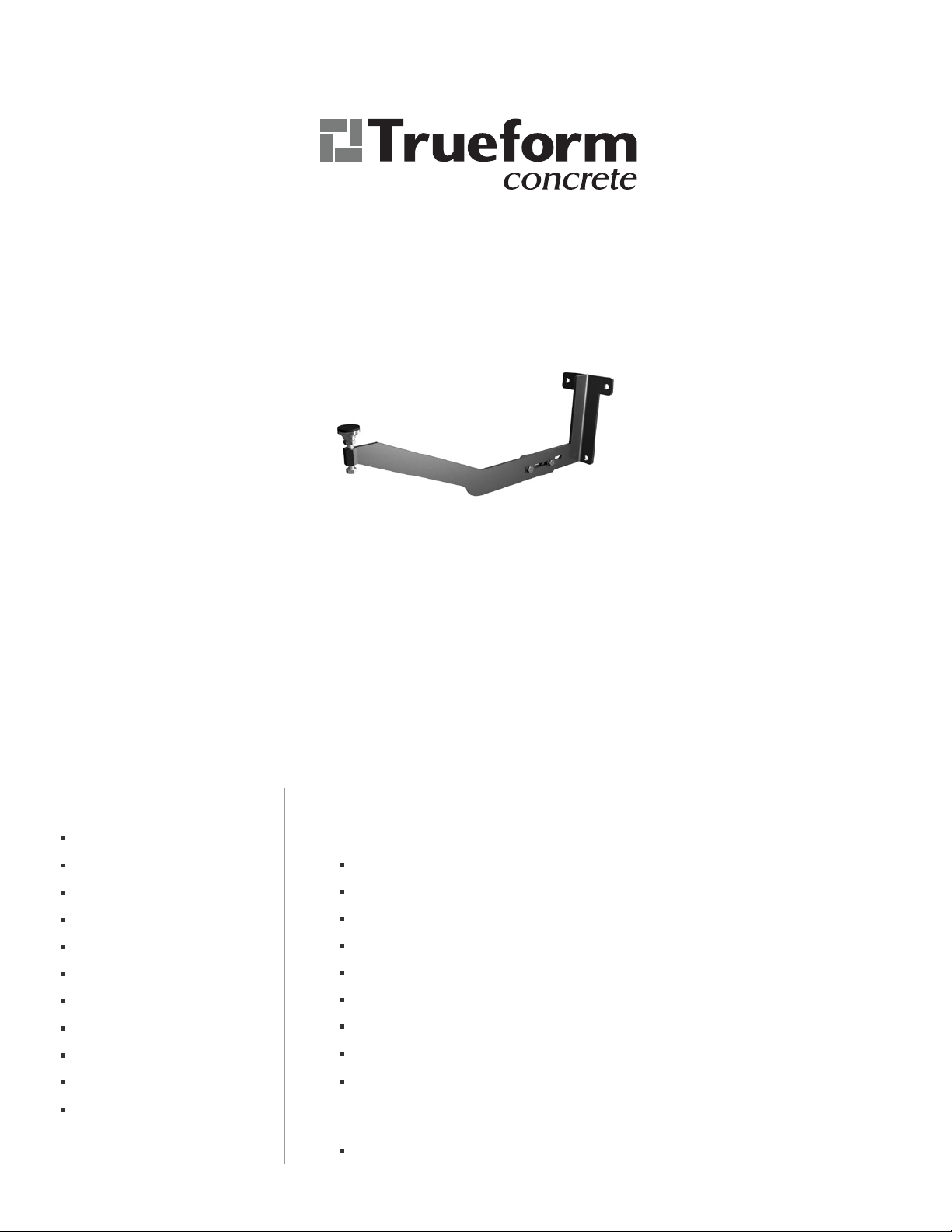
ADJUSTABLE CMU BRACKETS
FSB-B2-AS
FSB-B2-AL
APPLICATIONS
Trueform Adjustable CMU Brackets can be mounted to hollow CMU or other masonry surfaces.
TOOLS NEEDED INCLUDED HARDWARE
Pencil
Tape Measure
Laser level
Torpedo level
Hammer Drill
5/8” Hammer Drill bit
1/2” socket
1/2" box wrench
9/16” socket
Silicone
Shims
Part B2
Part AS or AL (depends on sink depth)
3/8” swivel foot (1 per bracket)
3/8” x 2” head head screw (1 per bracket)
5/16”-18 x 1” bolt (2 per bracket)
5/16”-18 nut (2 per bracket)
3/8” x 3” anchor rod (to be used with epoxy system)
3/8” epoxy sleeve (to be used with epoxy system)
3/8” lock nuts
REQUIRED BUT NOT INCLUDED
Hil HIT-HY 270 Masonry Chemical Anchor (epoxy system)
Each Adjustable CMU Bracket (FSB-B2-AL or FSB-B2-AS) includes the following:

Page 2 of 4
Step 1. Installing the CMU Mount (Part B2)
Each Adjustable CMU Bracket has 2 parts:
It is important to note that brackets must be perfectly leveled, both independently and to each
other. Do not measure from the floor when leveling brackets since the floor may not be level.
1. Mark the stud wall where you would like the center of the sink to be.
2. Determine the desired finished sink height and mark the stud 1” below. For example, a finished
height of 34” (ADA height) would result in a mark at 33” from the finished floor. This is your
B2 Installaon Height (B2-Height).
3. Set your laser level to the B2-Height.
4. Mark lateral locaons along the wall that meet the following criteria:
Maximum distance between a bracket (center of horizontal arm) and an unsupported
edge of the sink (le or right side) does not exceed 6“
Maximum distance between any two brackets (center of horizontal arm), or between a bracket
and a wall cleat supporng the le or right edges of the sink, does not exceed 32”
Minimum distance between a bracket (center of horizontal arm) and a sink drain locaon is 4”
5. Posion Part B2 so that the very top edge of the wall plate meets the B2-Height and the vercal
length is plumb (shim as necessary).
6. Use your torpedo level to ensure the horizontal arm is level.
7. Mark the wall and drill the holes for the anchor rods using the 5/8“ hammer drill bit.
8. Repeat steps 5-7 for each Part B2.
9. Refer to Hil’s manufacturing instrucons to install the masonry anchors. Note that epoxy
sleeve anchoring systems typically require a minimum cure me.
10. Once the epoxy has cured, secure Parts B2 to the anchor rods using the 5/16”-18 nuts.
B2: CMU Mount
AS or AL: Supporng Arm
B2 comes in a single size and must be
installed such that brackets will be both
level and spaced across the mounting
wall properly.
The arm will arrive to you in one of two
lengths and is determined by the
countertop depth of your sink:
AL(Long): Counter depths 20 1/2” - 24”
AS(Short): Counter depths 17” - 20 1/2”

Page 3 of 4
Step 3: Cleang & Seng the Sink
Step 2: Aaching & Seng the Supporng Arm (AS or AL)
1. Cleang is oponal but recommended. If cleang, install horizontal cleang on the back wall (and
side walls, if applicable) between brackets. Ensure that the top edges of all cleats are flush with the
top edges of all brackets. Also ensure the distance between any side wall cleat and a bracket does
not exceed 32”
2. When the heights and measurements of all components are verified, apply silicone to contact points
(top of swivel feet, very top edge of each bracket, and top of each cleat [if applicable]). The sink is
now ready to be set.
3. When seng the sink, the very top surface of the bracket (against the wall) will contact the
underside of the 1” thick countertops at the back of the sink. The swivel feet will make contact with
a built-up surface underneath the front of the sink apron (either by plywood or concrete). Note that
your sink will arrive with this surface already prepared.
4. Ensure that all all swivel feet are making contact with the underside of the sink, and use the 9/16”
socket to adjust the swivel feet height as necessary to level the sink.
1. Aach parts AL or AS slightly less than hand-ght to parts B2 using the 5/16”-18 nuts and bolts
so you can adjust their final locaons.
2. Set the distance from the center of the swivel feet to the finished wall, which is determined by
subtracng 1-3/4” from the overall countertop depth.
3. Use the 1/2” socket and 1/2” box wrench to ghten the hardware. Due to the tolerance between
the bolts and the slots, it is important to apply slight downward pressure on the swivel foot
during this step. The top surfaces of Parts B2 and AL or AS should be flush.
4. When all brackets are complete, the swivel feet should be level with each other and approximately
2 1/4” below the finished sink height when the leveling screws are midway between the top
and boom posions with room for adjustment in both direcons.

Page 4 of 4
The following instrucons are for our indoor products sealed with our topical sealer.
Now that your concrete is installed, you'll want to properly care for it. Follow these simple guidelines to keep your concrete
looking beauful for years to come:
Avoid dragging sharp, hard objects across the concrete surface to prevent scratching. Minor white scratches should be
expected throughout the piece from use over me. Applying Pledge every now and then can fill in minor scratches and give
your pieces a nice sheen.
Avoid using or leaving acidic foods and beverages (lemon juice, mustard, vinegar, wine, soda, tomatoes, bananas,
pumpkins/gourds, etc.) perfumes and colognes, cleaners that contain vinegar or citric acids, and other harsh chemicals or
solvents (ammonia, acetone, hydrogen peroxide, etc.) on the concrete surface. Clean or remove these substances as soon as
possible as they may “eat” through the sealer (which can leave a light hazing) and could possibly expose or stain your
concrete. There are, of course, other items and products that may damage your sealer. We have tested against the most
typical stain agents, but please use standard precauons to keep your concrete protected.
Avoid using abrasive soaps, cleansers, or scrubbing pads that can wear down the sealer. We recommend using mild,
non-abrasive, non-ammonia, non-citric acid, non-vinegar, non-bleach soaps and cleaners.
Please use standard care and precauons with your concrete products. Concrete is extremely durable; however, it is not
invincible. Excessive force can do damage to your piece.
Product Care & Maintenance
TRUEFORM warrants for a period of one (1) year from the date of delivery that its Products shall perform in a good and workmanlike manner
in accordance with applicable standards; comply with any applicable laws, rules or regulaons; and not violate or infringe upon any presently
issued patent or copyright of any third party. This warranty does not include or cover 1) hairline cracks in the concrete, 2) damage caused
during installaon or due to incorrect installaon, 3) damage caused by incorrect cleaning or care, 4) damage caused by incorrect use, 5)
damage caused by acts of abuse to the products such as scratches, chips, stains, or other markings/damage, or 6) damage caused by drilling
into or aempng to alter the product from the way in which it was received.
THE FOREGOING WARRANTIES ARE TRUEFORM’S ONLY WARRANTIES CONCERNING THE PRODUCTS, AND ARE MADE FOR THE
BENEFIT OF THE CUSTOMER ONLY AND ARE IN LIEU OF ALL OTHER WARRANTIES OR REPRESENTATIONS, EXPRESS OR IMPLIED,
INCLUDING, BUT NOT LIMITED TO, ANY IMPLIED WARRANTIES OF MERCHANTABILITY AND FITNESS FOR A PARTICULAR PURPOSE
OR OTHERWISE.
TRUEFORM’s sole responsibility is limited to the repair or replacement, at its own expense, of any non-conforming TRUEFORM Products
discovered by the Customer and reported to TRUEFORM within seven (7) days from the date of delivery.
TRUEFORM SHALL HAVE NO LIABILITY OR OTHER RESPONSIBILITY TO THE CUSTOMER OR ANY THIRD PARTY WITH RESPECT TO
ANY LIABILITY, LOSS OR DAMAGE ALLEGEDLY CAUSED DIRECTLY OR INDIRECTLY BY OUR PRODUCTS AND SERVICES AND THE USE
OF THIS MANUAL, INCLUDING, BUT NOT LIMITED TO, ANY INTERRUPTION OF SERVICE, LOSS OF BUSINESS, ANTICIPATORY
PROFITS, OR INDIRECT, SPECIAL OR CONSEQUENTIAL DAMAGES.
The material in this manual is for informaonal purposes only. The products it describes are subject to change without prior noce, due to the
manufacturer’s connuous development program.
If you have any quesons or if there is anything we can do to improve your experience, please let us know.
We’d be happy to hear your feedback.
Warranes, Limitaons of Liability and Exclusive Remedies
Quesons or Feedback?
For more informaon see our Product Care & Use Sheets at hps://www.trueformconcrete.com/product-care-use-sheets/
Trueform Concrete, LLC
105 W. Dewey Ave, Suite 509. Wharton NJ 07885
888.474.7977
info@trueformconcrete.com
www.trueformconcrete.com
This manual suits for next models
1
Popular Plumbing Product manuals by other brands


Triton
Triton T300si Installation and operating instructions

Moen
Moen KINGSLEY 6102 Series Specifications

American Standard
American Standard Williamsburg Deck Mount Tub Filler 2800.222 Specification sheet

Hans Grohe
Hans Grohe Massaud Tumbler 42234000 Dimensions

Signature Hardware
Signature Hardware VASSOR 953796 quick start guide

Pfister
Pfister XSpin 020-SPNX Quick installation guide

Saunatec
Saunatec S3-880 user manual

resideo
resideo Braukmann NK300S-SOFT installation instructions

Black & Decker
Black & Decker PricePfister 16 Series manual

American Standard
American Standard Oakmont Champion 4 2738.014 Specification sheet

Kraus
Kraus Aquila FVS-13900 installation manual

Aquavista
Aquavista H70K-51D-AV-CH quick start guide