TrueNAS ES12 User manual
TrueNAS®ES12 Expansion Shelf
Basic Setup Guide
Version 1.81

Copyright © 2022 iXsystems, Inc. All rights reserved. All trademarks are the property of their respective owners.
Contents
1 Unpacking the Unit ......................................................................... 1
2 Become Familiar with the ES12 .......................................................... 2
3 Rail Kit Assembly ............................................................................ 3
3.1 Rail Extenders ................................................................................... 3
3.2 Rail Spring ....................................................................................... 3
3.3 Attaching Rails to the Rack ................................................................... 4
4 Install Drive Trays ........................................................................... 5
5 Connect Power Cables ..................................................................... 6
6 Connect SAS Cables ........................................................................ 6
6.1 X-Series .......................................................................................... 6
6.2 R-Series .......................................................................................... 7
6.2.1 R20 ................................................................................................... 7
6.2.2 R40 ................................................................................................... 8
6.2.3 R50 ................................................................................................... 9
6.3 M-Series ........................................................................................ 10
6.3.1 M40 ................................................................................................ 10
6.3.2 M50 and M60 .................................................................................... 11
7 Install Bezel (Optional) .................................................................... 12
8 Additional Resources ..................................................................... 12
9 Contacting iXsystems ..................................................................... 12

Page 1
The TrueNAS ES12 is a 2U, 12-bay, SAS3 (12 Gb/s) expansion shelf with dual expansion controllers and redundant
power supplies.
ES12 Expansion Shelf
ES12 Bezel
Set of rackmount rails. The rails have a specific
front end, identified by a label visible on the
left above. The front ends of the rails must be
installed facing the front of the rack.
A total of 12 populated or empty “air baffle” drive
trays. Trays must be installed in all bays to main-
tain proper airflow for cooling. Up to ten drive
trays are packed in a cardboard tray. Additional
drivetrays are packed with the accessory kit.
Accessory kit with 2 IEC C13 to NEMA 5-15P
power cords, 2 IEC C13 to C14 cords, and a set of
velcro cable ties.
Two 3-meter Mini SAS HD to Mini SAS HD cables.
TrueNAS units are carefully packed and shipped with trusted carriers to arrive in perfect condition.
If there is any shipping damage or missing parts, please take photos and contact iXsystems support immediately at
[email protected], 1-855-GREP4-iX (1-855-473-7449), or 1-408-943-4100.
Please locate and record the hardware serial numbers on the back of each chassis for quick reference.
Carefully unpack the shipping boxes and locate these components:
1 Unpacking the Unit

Page 2
2 Become Familiar with the ES12
The ES12 has front panel indicators for power, locate ID, and fault. The fault indicator is on during the initial pow-
er-on self-test (POST) and turns o during normal operation. It turns on if the TrueNAS software generates an alert.
The ES12 has two expansion controllers in a side-by-side configuration:
1. HD Mini SAS3 connectors (T1-T3)
2. Debug port (TrueNAS internal use only)
1. Ready (Green)
2. Locate ID (Blue)
3. Fault (Amber)
Controller 1
Power Supply 1
Controller 2
Power Supply 2
Page 3
3 Rail Kit Assembly
On racks that are 30 inches deep or less, skip to “3.2 Rail Spring”.
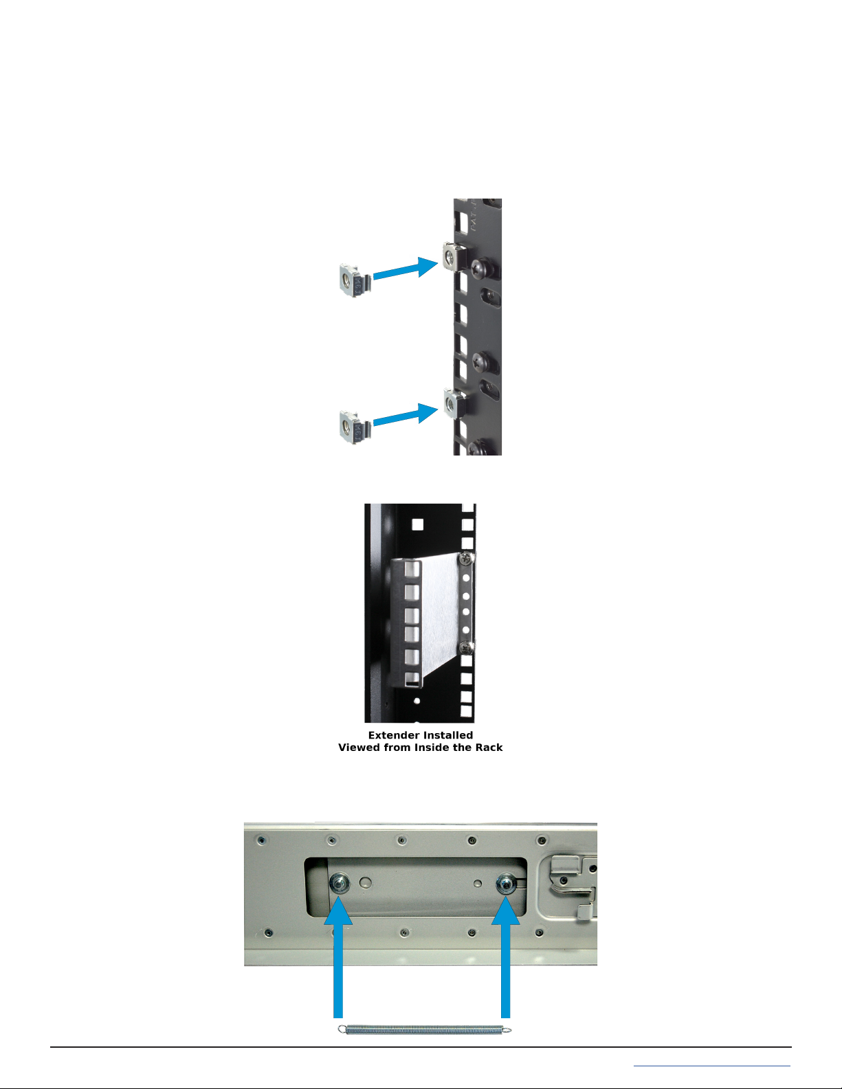
3.1 Rail Extenders
Racks from 31 to 36 inches deep require installation of the included rail extenders. For these deeper racks, install
cage nuts on the outside rear of the rack. The tabs on the cage nuts must be horizontal as shown.
Using the included bolts, install the rail extender inside the rear of the rack. Repeat the process for the second ex-
tender, which is a mirror image of the first.
3.2 Rail Spring
If not already present, install a spring on the silver posts in the side of each rail.
Page 4
3.3 Attaching Rails to the Rack
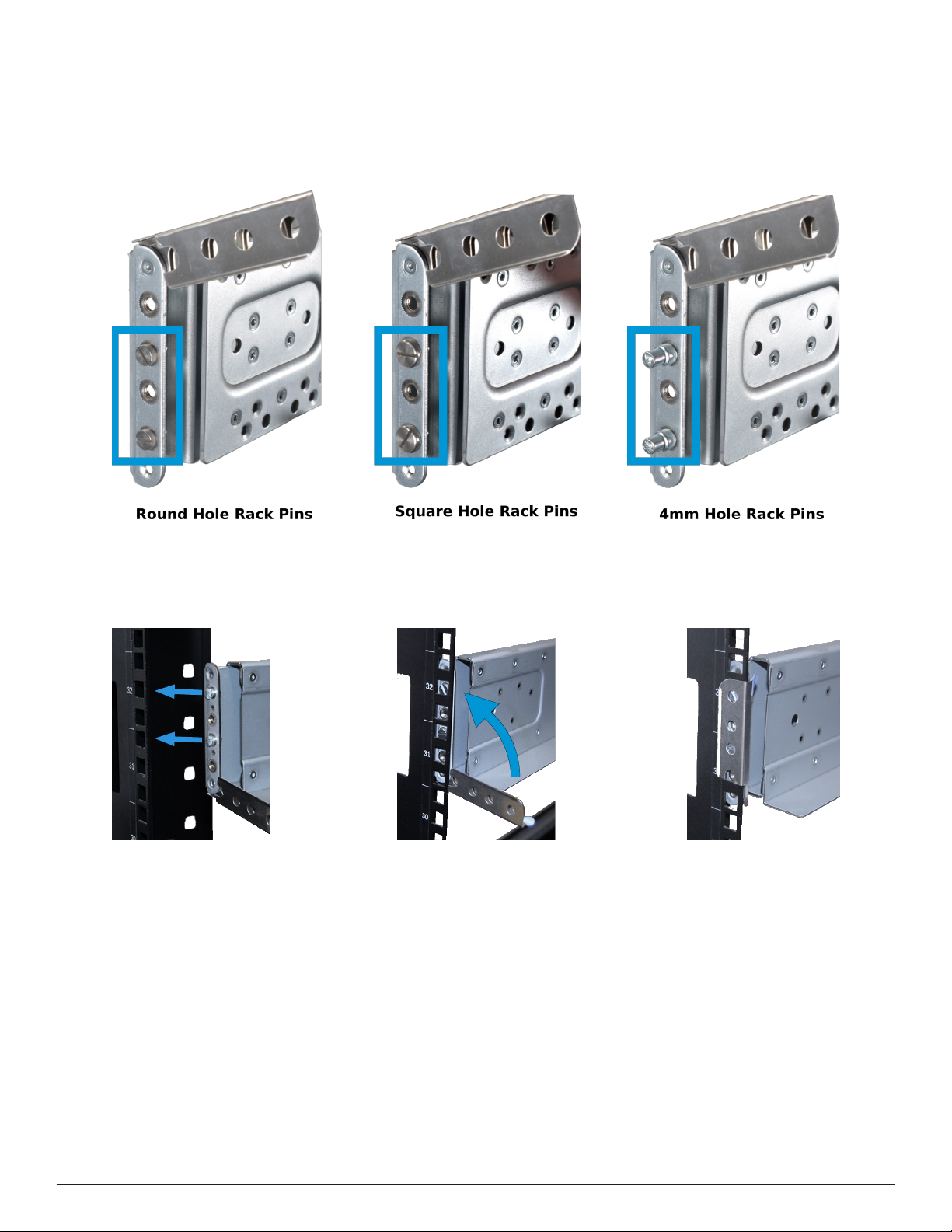
Chassis rails are configured to attach to round hole racks. Additional pins are included in the accessory kit to
configure the rails for square or 4mm hole racks. To reset the rails to fit a square or 4mm hole rack, unscrew the
pins at each end of the rails and replace them with the correct pins.
To secure a rail to the rack, open the clamp latches on the ends of each rail. Place the rail in the rack with the front
end toward the front of the rack, aligning the pins on both ends of the rail with the mounting holes in the rack.
Swing the clamp latch closed to hold the rail in place. Use two of the supplied screws to secure the back end of the
rail in place. Repeat the process for the second rail.
Caution: Two people are required to safely lift the chassis for rack installation or removal. Do not install
drives until after the chassis has been installed in the rack, and remove all drives before removing the chassis from
the rack. Carefully place the chassis onto the rails mounted in the rack. Push the chassis in until the ears are flush
with the front of the rack. If needed, attach the bezel. Use two of the supplied screws to secure each ear to the rack.
Page 5
4 Install Drive Trays
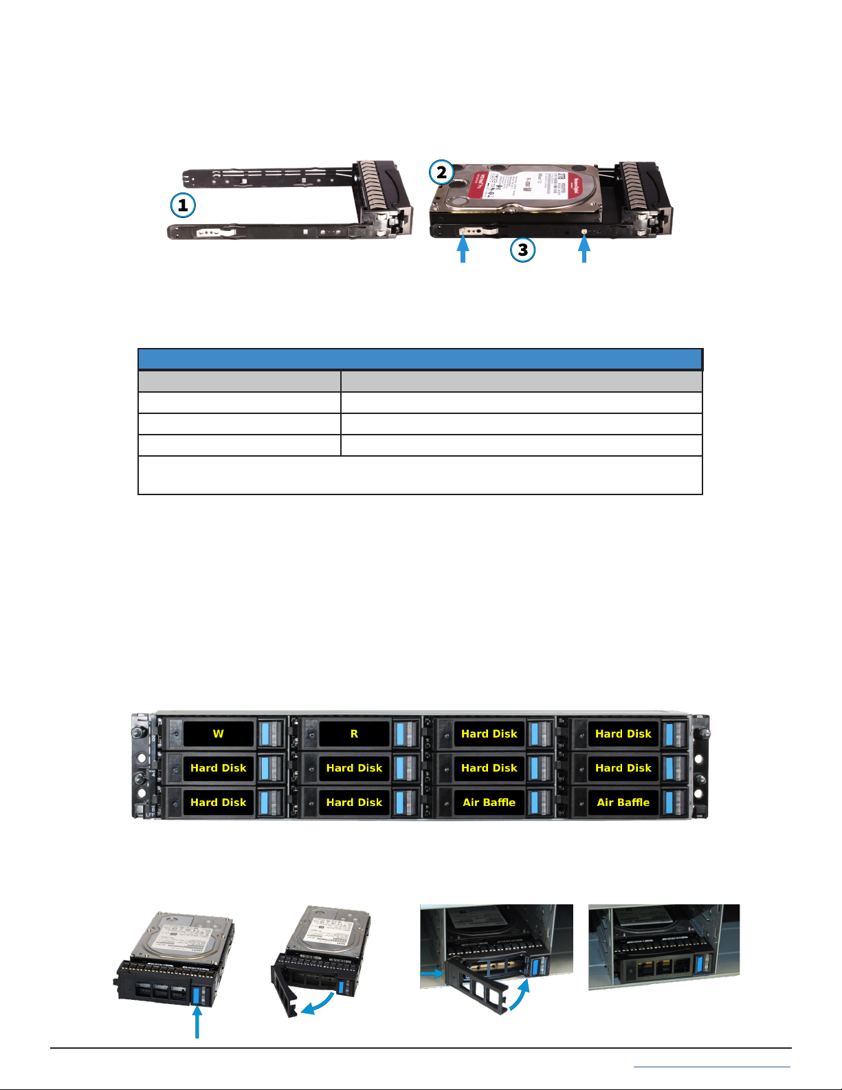
Trays must be placed in each drive bay to maintain proper cooling. If connecting fewer than twelve drives, place
“airbaffle” trays in the empty bays. We recommend a standard drive tray installation order to simplify support:
• SSD drive for write cache (W), if present
• SSD drive for read cache (R), if present
• Hard drives or SSD drives for data storage
• Air baffle filler trays to fill any remaining empty bays
Install the first drive tray in the top left drive bay. Install the next drive tray to the right of the first. Install remaining
drive trays to the right across the row. After filling a row with drives, move down to the next row and start again
with the left bay. This example shows the proper order for a write cache (W) SSD, a read cache (R) SSD, eight hard
drives, and two air baffle trays.
To load an individual drive tray into a bay, press the blue button to open the latch. Carefully slide the tray into a
drive bay until the left side of the latch touches the metal front edge of the chassis, then gently swing the latch
closed until it clicks into place.
TrueNAS systems only support qualified HDs and SSDs. Contact the Sales Team for more drives or replacements.
Adding unqualified drives to the system voids the warranty. Call Support if drives are improperly installed in trays.
Place the tray on a flat surface (1), mount the hard drive in the tray with the connector to the rear of the tray (2), and
secure the hard drive in the tray with four screws, two on each side (3).
Drive trays are used to mount drives in the chassis. Each drive tray has LEDs that denote its current status.
Drive Tray LED’s
Light Color/Behavior Status
Solid Blue Normal/Hot Spare
Blinking Blue Activity
Solid Amber Issue/Fault/Identify
Note for Samsung 1643a 2.5” SSDs:
Drive tray LED’s will only activate during drive activity or when there is a drive fault.
Page 6
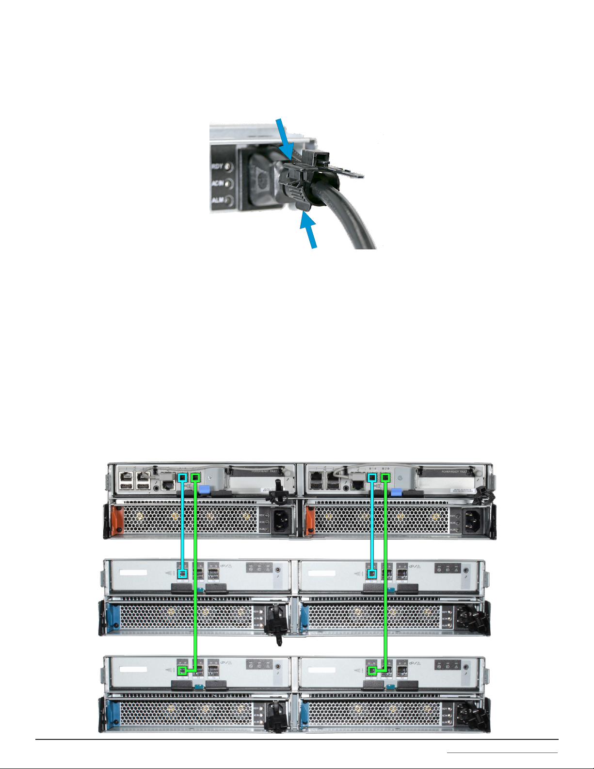
5 Connect Power Cables
Do not plug the power cords into a power outlet yet. Connect a power cord to the back of one power supply.
Place the cord in the plastic clamp and press the tab into the latch to lock it in place. Repeat the process for the
second power supply and cord.
6 Connect SAS Cables
Plug the ES12 power cords into power outlets. Wait two minutes for the drives to start. The ES12 is compatible
with several TrueNAS systems. Typical SAS cable connections for up to two ES12 expansion shelves on TrueNAS
High Availability (HA) systems are shown here.
6.1 X-Series
To set up SAS between your TrueNAS system and Expansion Shelves, cable the first port on the first TrueNAS
Controller to the first port on the first Expansion Shelf Controller. High Availability systems require another cable
from the first port on the second TrueNAS Controller to the first port on the second Expansion Shelf Controller.
We DO NOT recommend other cabling configurations. Contact iX Support if you need other cabling methods.
Warning: When setting up your SAS connections, please adhere to the wiring examples in this guide.
Connecting expansion shelves incorrectly will cause errors. Never cable a single controller to dierent
expanders on the same expansion shelf.


Page 11
6.3.2 M50 and M60
M50/M60 with three ES12 Expansion Shelves. The M50 can support up to 8 total Expansion Shelves with the use of
additional SAS cards. The M60 can support up to 12 total Expansion Shelves with the use of additional SAS cards.
M50/M60 with a single ES12 Expansion Shelf
M50 supports
up to 8
expansion
shelves
M60 supports
up to 12
expansion
shelves

Page 12
7 Install Bezel (Optional)
The included bezel is not required for operation. If desired, install the bezel by aligning it with the pins on the bezel
ears and pressing it into place.
8 Additional Resources
9 Contacting iXsystems
The TrueNAS Documentation Hub has complete software configuration and usage instructions. Click Guide in the
TrueNAS web interface or go directly to:
https://www.truenas.com/docs/
Additional hardware guides and articles are in the Documentation Hub’s Hardware section:
https://www.truenas.com/docs/hardware/
The TrueNAS Community forums provide opportunities to interact with other TrueNAS users and discuss their con-
figurations:
https://www.truenas.com/community/
For assistance, please contact iX Support:
Contact Method Contact Options
Web https://support.ixsystems.com
Email [email protected]
Telephone Monday-Friday, 6:00AM to 6:00PM Pacific Standard Time:
• US-only toll-free: 1-855-473-7449 option 2
• Local and international: 1-408-943-4100 option 2
Telephone Telephone After Hours (24x7 Gold Level Support only):
• US-only toll-free: 1-855-499-5131
• International: 1-408-878-3140 (International calling rates will apply)


Table of contents
Popular Indoor Furnishing manuals by other brands

Regency
Regency LWMS3015 Assembly instructions

Furniture of America
Furniture of America CM7751C Assembly instructions

Safavieh Furniture
Safavieh Furniture Estella CNS5731 manual

PLACES OF STYLE
PLACES OF STYLE Ovalfuss Assembly instruction

Trasman
Trasman 1138 Bo1 Assembly manual

Costway
Costway JV10856 manual


