Trueshopping 5 in 1 Petrol Installation and operating instructions

5 in 1 Petrol Multi Tool
Assembly / Owner’s Manual
©Trueshopping LTD Issue 01 mc-rt
Original Instructions

CONTENTS
GENERAL
Model Guide 3
Safety instructions a,b,4
Protecting yourself 4
Fuelling 4
Vibrations 4
Protecting others 4
Protecting the machine 5
Minimum Age 5
Recommended use 5
Emergency action 5
Safe operating instructions 5
Fuel Safety 6
What’s in the box? 6
Contents list 6
The multi tool engine driving unit 6
The engine 7
ASSEMBLY/OPERATION
Attaching the handle 7
Pole attachment 8
Shoulder harness assembly 9
Starting the multi tool 9
The hedge cutter
Hedge cutter parts 10
Hedge cutter assembly 10
Strimmer / brush cutter assembly
General operation advice 11
Adjusting the strimmer cord 11
Strimmer parts 11
Brush cutter parts 11
Attaching the guard / line cutter 11
Attaching the brush blade 14
Attaching the bump head 16
The Pruning saw
Guide rail / chain mounting 17
Tensioning the chain 18
Filling with oil 18
Operation advice 18
Adjusting the idle screw 19
MAINTENANCE
Fuel pipe / grommet exchange 19
Fuel filter exchange 21
Changing / checking the spark plug 24
Air filter cleaning / exchange 25
Carburettor exchange 26
Refilling the strimmer head 28
General maintenance
The engine 30
Guide rail (chain pruner) 30
Chain maintenance 30
The strimmer / brush cutter 31
Maintaining the bevel gear 31
The hedge trimmer 31
FAULT FINDING
Online help 32
Specifications 33

THIS GUIDE COVERS THE FOLLOWING
MODEL NUMBERS –
MT260 /MT260O
BC3304IN1 / BC3304IN1O
HLMP4304IN1 / HLMP4304IN1
HYM524IN1 / HYM524IN1O
MT550 / MT550O
MT580 / MT580O
MT620 / MT620O
MT650 / MT650O
MT680 / MT680O
*While every effort is made to ensure the
accuracy of the information in this
manual,occasionally minor design
changes can occur, ifin doubt please
visit the manufacturers website for the
most up to date version of this guide .
3

Warnings on the Machine and their
Meanings
Information on the long reach hedge and
pruner attachments
Model Information
(location differs by model)
CAUTION! HOT EXHAUST
DO NOT USE NEAR
NAKED FLAMES
Machine Noise
information
Clockwise from left -
Danger of kickback
Keep feet away from
guard and blade
Watch your step
Beware of thrown
objects
Keep working area
clear of pedestrian
traffic
Ensure you have adequate
space to work
a.
Important
information

IMPORTANT SAFETY INFORMATION
•Please note that the cutting blade
continues to run for a short period
after you let go of the throttle trigger
–This is called the flywheel effect.
•Do not lend or rent your power tool
without the instruction manual. Be
sure that anyone using your power
tool understands the information
contained in this manual.
•Persons with pacemakers only: The
ignition system of your power tool
produces an electromagnetic field of a
very low intensity. This field may
interfere with some pacemakers.
Consult your doctor if you have
concerns.
•Do not use a pressure washer to clean
your power tool. The solid jet of water
may damage parts of the power tool.
•Do not spray the machine with water.
•Work calmly and carefully – in
daylight conditions and only when
visibility is good. Stay alert so as not
to endanger others.
•Your power tool produces toxic
exhaust fumes as soon as the engine
is running. These fumes may be
colourless and odourless and contain
unburned hydrocarbons and benzoyl.
Never run the engine indoors or in
poorly ventilated locations.
•The dusts, vapour and smoke
produced during operation may be
dangerous to health. If the work area
is very dusty or smoky, wear
appropriate safety equipment.
•If your power tool is subjected to
unusually high loads for which it was
not designed (e.g. heavy impact or a
fall), always check that it is in good
condition before continuing work
•When working at heights:
–Always use a lift bucket
–Never work on a ladder or in a tree
–Never work on an insecure support
–Never operate your power tool with
one hand.
Be alert and cautious when wearing hearing
protection, your ability to hear warnings
(alarms, etc.) is restricted.
TUV IDENTIFICATION
LABEL
b.
Attachment information

Safety Instructions
Read this manual in full before operating the
machine for the firsttime. If you have any
questions regarding the operation ofthe
machine, please contact the manufacturer.
CAUTION! In order toensure your safety you
must follow the safety, installation and
operation instructions. Any person who uses
this machine should be fully aware of the
potential risks.
!You must be 18orover to operate this
machine. Children must notoperate this
machine.
! The manufacturer shall not be held liable if
the unit is altered outside of the information
printed in this guide.
! Always turn the engine off before
performing any maintenance
!Some components will become hot
during use, specifically – the engine, bump
head, brush cutter blade, hedge trimmer
and pruning saw.
Protecting Yourself
!Donotusethis machine in areas with poor
ventilation or indoors, when switched on,
the machine produces carbon monoxide!
!Donotoperate this machine in adverse
weather conditions orin situations where
sure footing is not guaranteed.
! Exercise common sense when operating
this machine, do not operate when under the
influence of alcohol or medication which
may impair judgement and concentration.
FUELLING
! Always switch the engine off before
fuelling.
Open the tank cap slowly to avoid spillage due
to internal pressure. If the unit has recently
been in use, allow to cool down first. Not
allowing the unit to cool could cause the fuel
to ignite.
When replacing the fuel, be careful not to
over fill the tank. Any spillages should be
cleaned up immediately.
After filling ensure that the cap is secured
properly and that it will not work loose while
the machine is switched on.
VIBRATIONS
Vibrations from the machine make it difficult
to hold for long periods of time, this time can
be prolonged by wearing suitable gloves.
Protecting others
! Do notallow anyone toapproach the
machine while in use, ensure the working
area isclear.
! Avoid jamming the blade as this can make
the machine suddenly difficult to control.
! WEAR EAR PROTECTION!
! SAFETY BOOTS MUST BE WORN
WHILE OPERATING THE MACHINE!
! WEAR SUITABLE EYE
PROTECTION!
! WARNING, PETROL IS
FLAMMABLE, TAKE
APPROPRIATE CARE!
4

! Never use the brush cutter or strimmer
bump head without the guard attached as
objects can be thrown up.
!Donotusethe machine for any purposes
other than outlined in this manual.
!Itis good practise to clearly mark your
working area.
! Turn the machine off when moving
location.
Protecting the Machine
! Only use recommended parts, consult the
manufacturer to obtain these.
! Always use the correct tool for the correct
job. Use the tool only for its designed
purpose.
! Only use non-metallic fibre in your
strimmer.
! Ensure that the machine is stored in a dry
area in a secure place. Parts of the tool are
sharp and should not be left within reach of
children / pets.
! Inspect the machine for damage before use,
and ensure all components are properly
aligned.
! Use of third party strimmer heads can
potentially cause damage to the machine
Minimum Age
Only persons over 18 years of age are legally
allowed to operate this machine unless under
training supervision.
Recommended use
The unit is recommended for general use in
agriculture, forestry and gardening.
Emergency Action
In the event of injury, seek qualified medical
assistance and apply first aid to the injury. If
you are the responder, protect the injured
person from further injury.
! The user is responsible for any material /
personal damage resulting from improper
use.
! Please note that if not properly used, the
following injuries can be caused –
Contact with an uncovered Strimmer head –
Laceration
Reaching into the running scythe –
Laceration
Hearing problems if proper ear protection
not used
Carbon monoxide poisoning if used in an
enclosed area.
Safe Operating Instructions
! Do not operate the machine if you suspect
the machine has a problem.
•Always visually inspect tosee that the
blades and bolts are secure. Ensure
the engine vents are freefrom any
dirt or remnants.
•Operate the machine at the lowest
possible engine speed to do the job.
•Keep your hands and feet clear of the
attached tool when the machine is
running.
•Keep both hands firmly on the
machine at all times.
•Always use the machine with the
supplied carry strap.
•Always wear appropriate hand, feet
and hearing / eye protection when
operating the machine.
•Do not use metal cutting coils.
•Pay attention, the machine will
continue to run for five seconds after
the engine has stopped.
5
Fuel safety
! Petrol is highly flammable. Take the
following precautions:
•Store fuel in containers specifically
designed for this purpose. DO NOT store
in the mixing bottle.
•Refuel outdoors only and do not smoke
while refuelling.
•Add fuel before starting the engine. Never
remove the fuel cap when the engine is
running or the engine is hot.
•Avoid spillage. If petrol is spilled, do not
attempt to start the engine, move the
machine away from the spillage to avoid
any danger of petrol vapours igniting.
•Tighten the fuel tank cap tightly.
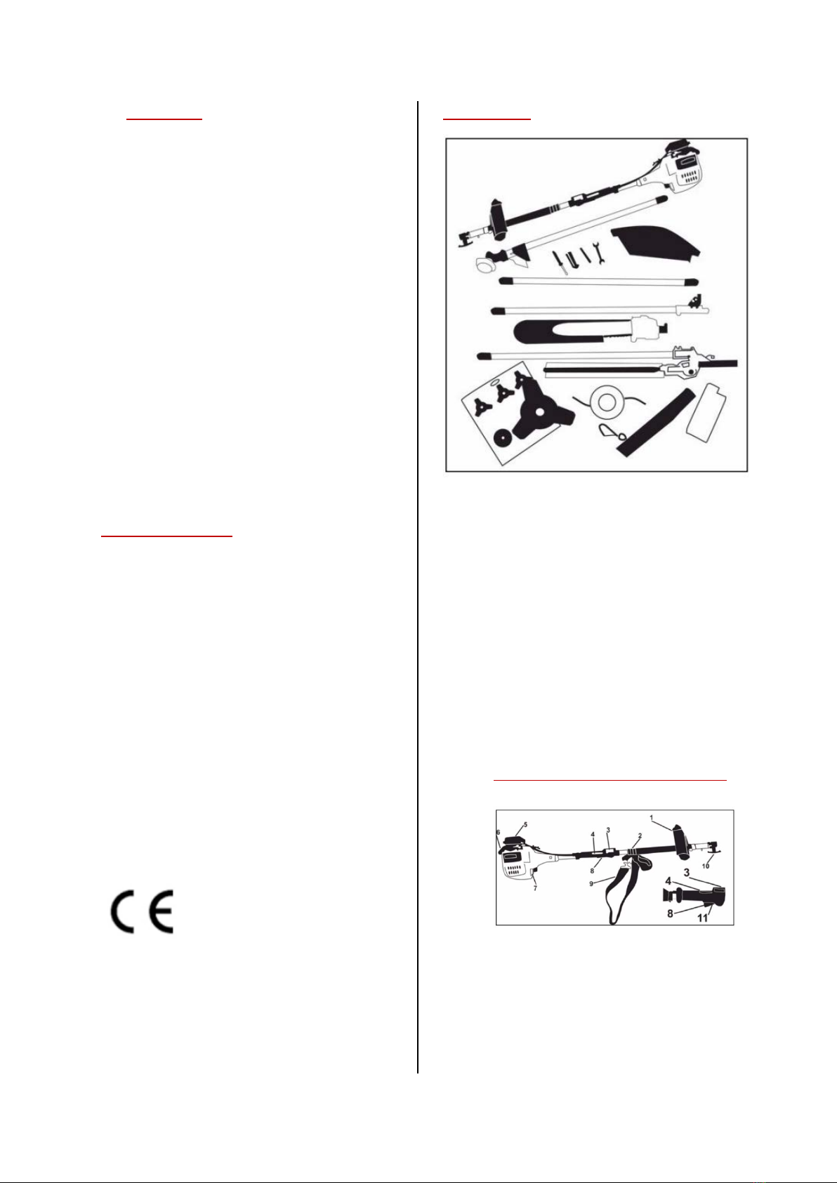
What’s in the box?
This is a universal tool which will enable you
to care for your garden. With this machine
you can cut the lawn,hedgerowsand lop tree
limbs .This machine is powered byan easy
starting,reliable air cooled single cylinder 2
stroke engine.Using a fuel/oil mix of25:1 and
producing 1.2hp at11,000rpm itmakes easy
work ofmost garden tasks. Afoam air filter
prolongs engine life and the centrifugal clutch
automatically engages, driving the tools only
when required.
All of the incorporated tools are easy to
attach to the main engine unit as required.
Contents list
•Main engine with handle attached
•Strimmer
•Tools
•Strimmer/cutter Guard
•Extension handle
•Handle to chain pruning saw
•Pruning saw blade
•Hedge trimmer
•Cutter blade
•Strimmer spool
•Carry strap
•Petrol mixing bottle
The multi tool engine driving unit
1. Handle
2. Harness loop hole
3. Stop switch
4. Throttle lockout
5. Air filter
6. Start handle
6

7. Fuel tank
8. Throttle trigger
9. Shoulder Harness
10. Unit attachment locking screw
The Engine
1. Filler cap
2. Choke lever: Facilitates the engine
starting.
3. Fuel Pump: increases fuel supply
when cold starting.
4. Carburettor screw: For adjusting the
idling speed.
5. Engine support : For supporting the
machine when on the ground
6. Fuel tank: For storing a fuel mixture
comprising of petrol and engine oil.
7. Exhaust (with spark arrestor):
Reduces operating noise and directs
the exhaust gas away from the
operator.
Attaching the handle
•The handle fits over the plastic mounting
bracket which is already attached to the
upper pole.
•The handle consists of two parts ( 1 & 2 )
•Place part 2 onto the underside of the
mounting bracket and hold it in place with
your hand. Push four hex nuts into the
recesses beneath part two and hold them
in place with your fingers.
1
2
7

•Place part 1 onto the mounting and line
the holes up with the holes on part 2.
Then fix the four Allen bolts through the
top of part 1 to fix in place.
Pole Attachment
To attach the different attachments to the
machine, you need to connect them to the
coupling on the end of the fixed engine pole.
1. Open the coupling and turn the retaining
handle to loosen the connection.
2. Line up the hole on the required tool
pole as shown below and push firmly
into the coupling.
3. Close the coupling again, tighten the
retaining handle, and pull and twist
the pole to ensure that it is secure.
8

Shoulder harness assembly
The shoulder harness clips to the handle of the
main engine as shown below.
Starting the Multi tool
! Please be aware that a certain degree of
effort is required to successfully start the
multi-tool, please persevere if you are
struggling to start the engine.
•Pull the switch into the on “I” position and
hold the throttle lockout and then pull the
throttle trigger.
•While still holding the above, press in the
switch next to the on/off switch .
•Slowly release all three and you should
note that the switch stays pressed in.
•Now we need to prime the engine with
fuel for use. Press the priming bulb on the
unit several times (8-10) to prime the
machine.
•To start the engine, push the choke lever
upwards and pull the starter cord.
9
•Do this until you hear a splutter or cough
from the engine. Once this has happened,
push the choke lever down and pull the
starter cord and the engine will start. You
can then pull the throttle trigger to start
the tool working.
**Please note that it can take several
attempts at pulling the starter cord to
start the machine.
•To turn the machine off push the on/off
switch to “O”.
The Hedge cutter
The hedge cutter is ready assembled and just
needs to be attached to the main engine unit.
Refer to the “Pole attachment” guide on how
to do this.
When you are ready to use the hedge cutter
ensure that the unit is switched off and then
remove the plastic guards from the blades
**TAKE CARE WHEN HANDLING THE HEDGE
CUTTER AS THE BLADES ARE SHARP **
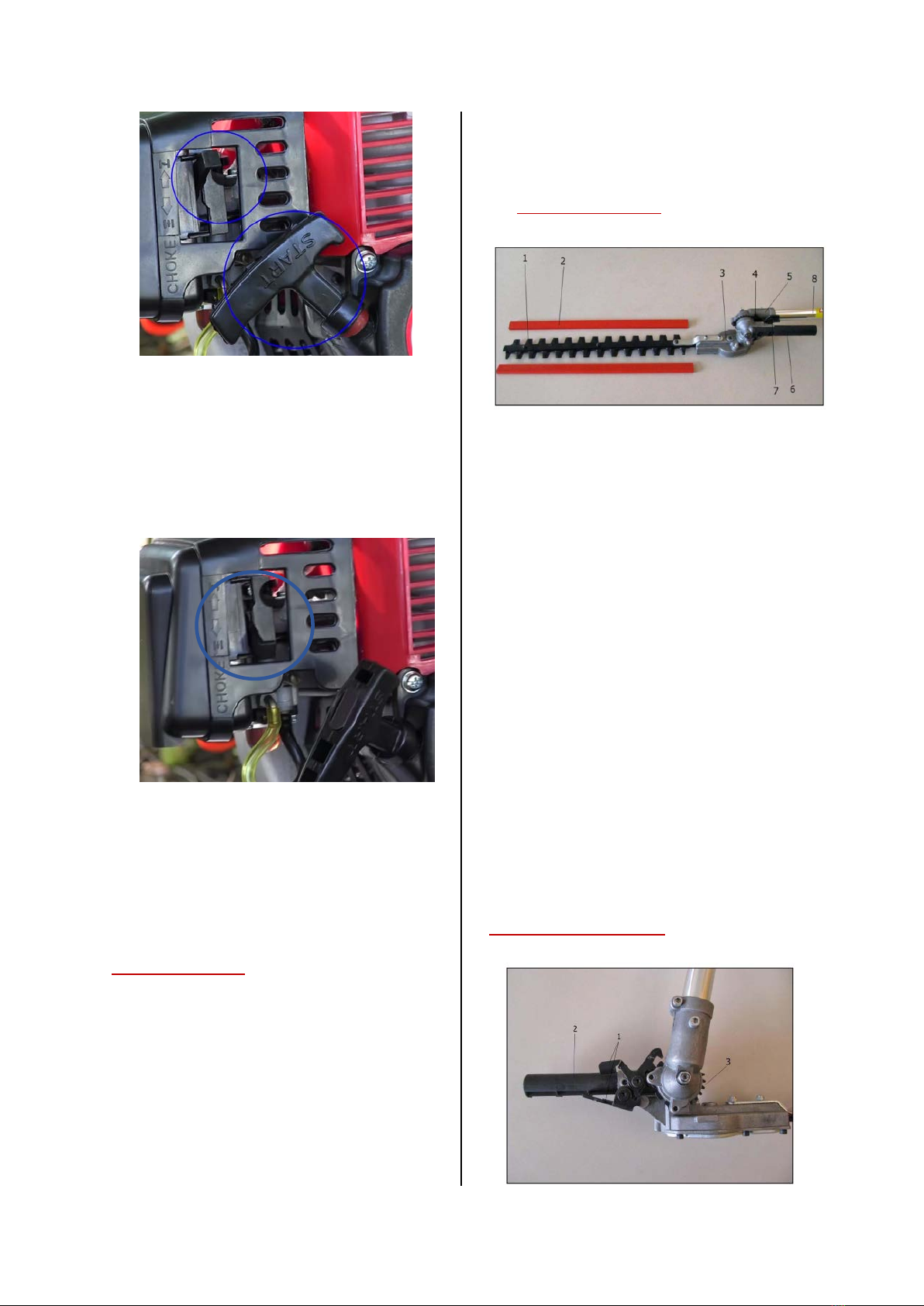
Hedge cutter parts
1. Cutting blade: Steel blade for cutting
hedges and bushes.
2. Blade Guard: Protect the cutting rail
when the tool is not in use.
3. Blade gear: Convert the rotation of
the angle gear when the cutting blade
moves back and forth.
4. Locking mechanism: Holds the cutter
in the desired position.
5. Angle Gear: Transmits the rotational
movement of the drive axel to the
blade gear.
6. Adjusting lever: Adjust the cutting rail
to the desired angle.
7. Locking lever : Lock and unlock the
cutting rail
8. Drive shaft tube: Surrounds and
protects the drive shaft between the
coupling sleeve and gear.
Hedge cutter assembly
10

1. Unfold the hedge cutter
attachment by pressing the two
locking levers (1)
2. While still pressing the locking
levers rotate the adjusting lever
(2) to the desired angle, then fix
the locking lever to the gear ring.
Strimmer / brush cutter assembly
General operation advice
!Any hard objects e.g. Stones, metallic and
plastic objects should be removed from the
area before operation. Otherwise they can
be thrown up and cause damage tothe
machine and Injury.
! Grass height in the working area should not
exceed 15cm due to the danger of hidden
Debris.
!Only for useon grass, weeds and low
shrubbery.
! When the unit is running, never put the
strimmer / brush cutter on the ground.
! Never cut above shoulder height and
ensure you have firm footing at all times.
! If you are unsure about any of the
procedures outlined, please contact the
manufacturer.
Adjusting the strimmer cord
! The strimmer head will still run for a short
time after switching off the machine. Wait
until the machine comes to a complete stop.
When the strimmer cord becomes too short
after use, tap the spool head on solid ground
several times. This will unlock the spool head
and extend the cord through centrifugal force.
The line cutter will automatically trim it to the
correct length.
Strimmer parts
Brush cutter parts
12. Blade
13. Line cutting knife
14. Mounting screw and washer
15. Mounting washer
16. Blade protection
17. Locking nut
18. Spacer disc
Attaching the guard / line cutter
! Be careful when handling the line cutter, it
is sharp.
!The guard must be attached when using
either the strimmer orbrush cutter
The following parts are required to fit the
guard and line cutter
4 x locking bolts
4 x locking nuts
4 x washers
1 x 4mm Allen key
1 x spanner
•Loosen the metal mounting bracket using
the 4mm Allan key and spanner
11

•Once loosened, pull the metal bracket
away from the plastic mounting on the
pole.
•Place the blade guard uptothe mounting
bracket.
•Make sure that the holes on the mounting
bracket and blade guard line-up.
•Insert the locking bolts through the plastic
retaining bracket on the main pole.
•Fasten them both together using the Allen
key, locking nuts and washers.
12
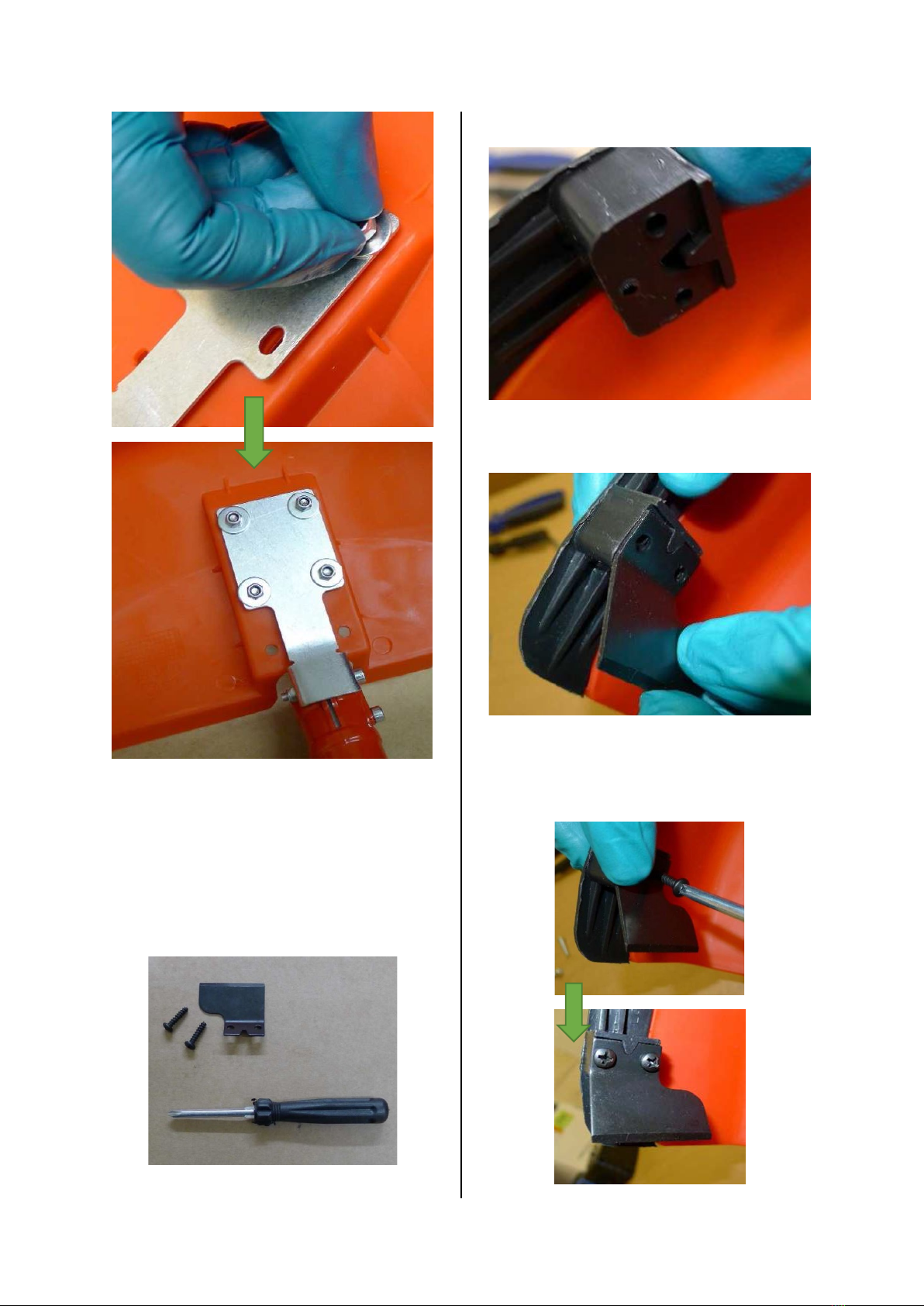
Now that the guard is attached, we will now
fix the line cutter in place. To do this you will
need –
1 x Line cutter
2 x Phillips screws
1 x small Philips screwdriver
•Locate the mounting block on the guard.
•Place the line cutting blade upto the
mounting block asshown.
•Fix the blade to the mounting block using
the two Philips screws.
13

The line cutter is now attached.
Attaching the brush blade
! Please be careful during this procedure, the
brush blade is sharp.
The following parts are required for fitting the
brush blade –
1 x Brush blade
1 x 4mm Allen key
•Remove the nut on the head assembly by
rotating it clockwise.
•Once the nut is removed, pull the bell
shaped washer away from the head
assembly.
•Now lift and remove the flat spacer
washer from the head assembly.
•Line up the hole on the side of the large
washer with the hole in the side of the
head assembly.
Insert the 4mm Allen key through both holes
(This will prevent the head from rotating
while you attach the blade).
•Now carefully remove the brush blade
from the packaging.
14

•The blade must be mounted with the
directional arrow on the blade and the
directional arrow on the guard pointing in
the same direction.
•Next we mount the blade onto the large
washer on the head assembly as shown.
! The blade must sit correctly onto the head
assembly, an improperly mounted blade can
cause damage / injury.
•Now re-fix the small spacer washer onto
the central spindle, ensuring the recessed
side of the washer faces the blade.
•Re-attach the bell shaped washer and
locknut while holding onto the Allen key.
15

•Finger tighten the locknut anti clockwise
and then tighten fully with the socket
tool.
•Finally, remove the Allen key.
•The blade in now ready for use.
Attaching the Bump head
This instruction shows you how to attach the
strimmer bump head to your multi tool.
•Remove the nut and large bell washer
from the head assembly (as shown in the
brush blade instruction)
•Rotate the large washer until the hole in
the side lines upwith thehole on the
head assembly. Then insertthe 4mm
Allen key through the two holes to
prevent the assembly frommoving.
•Pick up the bump head and place the
threaded connection on the bump head
onto the threaded connection point in the
centre of the head assembly.
•Screw the bump head onto the central
fixing by rotating it anti clockwise, it is
important that you hold the Allen key
16

while doing this otherwise the head will
turn indefinitely.
•The unit is ready for use once the bump
head stops turning.
The Pruning Saw
The pruning saw is designed for cutting
hard to reach branches. It is not designed
to be used in the felling of trees.
The extension pole can be used with the
pruning saw, see the section “pole
attachment” for advice on attaching to
the main engine unit.
**When you are ready to use the pruning
saw, carefully remove the protective
cover. Ensure that the engine is off and
take care when handling as the saw teeth
are sharp **
Guide rail / chain mounting
•Loosen the nut and remove the
chain guard.
•Tighten the adjuster with a
screwdriver so that it is all the
way to the right (circled) then sit
the bar in position.
•Put the chain in place and start
from the top end of the rail,
ensuring that the chain teeth go
around the bar as pictured.
17

•Place the plastic cover onto the
assembly and loosely screw the
nut on. (DO NOT TIGHTEN)
•Turn the tightening screw
(Circled) clockwise until the chain
on the underside of the rail is
slightly hung up and the links are
located into the groove of the
guide rail.
•Refit the chain guard and tighten
the nut by hand.
Tensioning the chain
A new chain has to be tensioned
frequently remember to check the
chain tension regularly.
To do this –
1. Stop the engine and loosen the
guard nut.
2. Keep the guide rail tip pointing
upwards.
3. Use a screwdriver to tighten the
clamping screw clockwise until the
chain once again rises tightly against
the underside of the rail.
4. Retighten the nut.
Filling with oil
To fill the chain pruner with oil.
•Remove the black plastic cap on
the chain pruner by turning it anti
clockwise.
•Fill with oil and then replace the
cap.
Operation advice
•Beware of falling branches and
branches that many spring back
•You must use the extension to get
to hard to reach areas, do not
lean.
•Do not use the pruning saw while
standing on a ladder, ensure you
have firm footing at all times.
18
Table of contents
Languages:
Popular Power Tools manuals by other brands

Specac
Specac Atlas Automatic 40 Ton user manual

Makita
Makita BTM40 instruction manual

Chicago Pneumatic
Chicago Pneumatic CP86150 Operator's manual

Pattfield Ergo Tools
Pattfield Ergo Tools E-PST 800 L operating instructions

Makita
Makita RP1111C instruction manual

Milwaukee
Milwaukee M18 2640-20 Series Operator's manual


