Trust X Series User manual

TRUST AIR CONDITIONING EQUIPMENT CO.
Prepared By: Engineering & R & D Department.
Shiraz- May 2017
(X SERIES)
INVERTER VRF SYSTEM

1
Installation
1Preface.................................................................................................2
2UnitPlacementandInstallation............................................................3
3OutdoorUnitDuctingandShielding......................................................6
4RefrigerantPipingDesign
6DrainPiping........................................................................................33
7Insulation...........................................................................................36
8ChargingRefrigerant...........................................................................39
9ElectricalWiring..................................................................................41
10 InstallationinAreasofHighSalinity....................................................45
11 Commissioning...................................................................................46
12 Appendix–SystemCommissioningReport...........................................49
2016
14 Centralized Controllers .................................................................55
15 Network Control System and Building Management Systems........55
13Individual Controllers ...................................................................55
..................................................................10
5RefrigerantPipingInstallation...........................................................11

2
1 Preface
1.1 NotesforInstallersBoxes
TheinformationcontainedinthisEngineeringDataBookmayprimarilybeofuseduringthesystemdesignstageofaTrust
V5XSeriesVRFproject.Additionalimportantinformationwhichmayprimarilybeofuseduringfieldinstallationhasbeen
placedinboxes,suchastheexamplebelow,titled“Notesforinstallers”.
1.2 Definitions
InthisEngineeringDataBook,theterm“applicablelegislation”referstoallnational,localandotherlaws,standards,codes,
rules,regulationsandotherlegislationthatapplyinagivensituation.
1.3 Precautions
Allsysteminstallationincludinginstallationofpipingandelectricalworksmustonlybecarriedoutbycompetentand
suitablyqualified,certifiedandaccreditedprofessionalsandinaccordancewithallapplicablelegislation.
Notesforinstallersboxescontainimportantinformationwhichmayprimarilybeofuseduringfieldinstallation,
ratherthanduringdesk‐basedsystemdesign.
Notesforinstallers

3
2 UnitPlacementandInstallation
2.1 OutdoorUnits
2.1.1 Placementconsiderations
Placementofoutdoorunitsshouldtakeaccountofthefollowingconsiderations:
Airconditionersshouldnotbeexposedtodirectradiationfromahigh‐temperatureheatsource.
Airconditionersshouldnotbeinstalledinpositionswheredustordirtmayaffectheatexchangers.
Airconditionersshouldnotbeinstalledinlocationswhereexposuretooilortocorrosiveorharmfulgases,suchas
acidicoralkalinegases,mayoccur.
Airconditionersshouldnotbeinstalledinlocationswhereexposuretosalinitymayoccurunlesstheanti‐corrosion
treatmentforhigh‐salinityareascustomizationoptionhasbeenaddedandtheprecautionsdescribedinInstallation
Manual,10“InstallationinAreasofHighSalinity”aretaken.
Outdoorunitsshouldbeinstalledinwell‐drained,well‐ventilatedpositionsthatareascloseaspossibletotheindoor
units.
2.1.2 Spacing
Outdoorunitsmustbespacedsuchthatsufficientairmayflowthrougheachunit.Sufficientairflowacrossheat
exchangersisessentialforoutdoorunitstofunctionproperly.Figures3‐2.1to3‐2.3showspacingrequirementsinthree
differentscenarios.
IftheparticularcircumstancesofaninstallationrequireaunittobeplacedclosertoawallthanspecifiedinFigures3‐2.1
to3‐2.3,adischargeductshouldbeinstalled.RefertoInstallationManual,3“OutdoorUnitDuctingandShielding”.
Dependingontheheightofadjacentwallsrelativetotheheightoftheunits,ductingmayberequired.RefertoInstallation
Manual,3“OutdoorUnitDuctingandShielding”.
Figure3‐2.1:Singleunitinstallation(unit:mm)Figure3‐2.2:Singlerowinstallation(unit:mm)
Figure3‐2.3:Multi‐rowinstallation(unit:mm)
Front1000 or more
1000 or more
1000 or more
1000 or more
100 to 500 100 to 500
1000 or more
1000 or more
1000 or more 1000 or more
Front
100 to 500
100 to 500
100 to 500
100 to 500
100 to 500
100 to 500
1000 or more
1000 or more
1000 or more
1000 or more
1000 or more
1000 or more
1000 or more
1000 or more
1000 or mor
e
1000 or mor
e
Front
Front
Front

4
2.1.3 Masterandslaveunitpositioning
Insystemswithmultipleoutdoorunits,theunitsshouldbeplacedinorderfromlargestcapacityunittosmallestcapacity
unit.Thelargestcapacityunitmustbeplacedonthefirstbranch,andbesetasthemasterunit,whiletheothersshouldbe
setasslaveunits.RefertotheV5XServiceManual,ControlManualfordetailsofhowtosetunitsasmaster/slave.
TheexampleinFigure3‐2.4illustratestheplacingofunitsina48HPcombination:
Placethe22HPunitonthefirstbranchandsetitasthemasterunit.
Placethe16HPand10HPunitsonthenextbranchesandsetthemasslaveunits.
Figure3‐2.4:Positioningofmasterandslaveunits
2.1.4 Basestructures
Outdoorunitbasestructuredesignshouldtakeaccountofthefollowingconsiderations:
Asolidbasepreventsexcessvibrationandnoise.Outdoorunitbasesshouldbeconstructedonsolidgroundoron
structuresofsufficientstrengthtosupporttheunits’weight.
Basesshouldbeatleast200mmhightoprovidesufficientaccessforinstallationofpiping.
Eithersteelorconcretebasesmaybesuitable.
AtypicalconcretebasedesignisshowninFigure3‐2.5.Atypicalconcretespecificationis1partcement,2partssand
and4partscrushedstonewithΦ10mmsteelreinforcingbar.Theedgesofthebaseshouldbechamfered.
Toensurethatallcontactpointsareequallysecure,basesshouldbecompletelylevel.Basedesignshouldensurethat
thepointsontheunits’basesdesignedforweight‐bearingsupportarefullysupported.Boltspacingsshouldbeasper
Figure3‐2.6andTable3‐2.1.
Adrainageditchshouldbeprovidedtoallowdrainageofcondensatethatmayformontheheatexchangerswhen
theunitsarerunninginheatingmode.Thedrainageshouldensurethatcondensateisdirectedawayfromroadways
andfootpaths,especiallyinlocationswheretheclimateissuchthatcondensatemayfreeze.
Outdoorunits
(48HP)
A(22HP) B(16HP) C(10HP)
Indoor
unitA
Indoor
unitB
Indoor
unitC
Firstoutdoor
branchjoint

5
Figure3‐2.5:Outdoorunittypicalconcretebasestructuredesign(unit:mm)
Figure3‐2.6:ExpansionboltpositioningTab le3‐2.1:Expansionboltspacings
Dimension(mm)8,10,12HP14,16,18,20,22HP
A7401090
B9901340
C723723
D790790
2.1.5 Acceptanceandunpacking
2.1.6 Hoisting
≥80
Outdoorunit
Concretebaseh=200
Φ10Expansionbolt
Rubberanti‐vibrationpads
Solidground/surface
200
15×23 long u-shape hole
B
A
C
D
Whenunitsaredeliveredcheckwhetheranydamageoccurredduringshipment.Ifthereisdamagetothe
surfaceoroutsideofaunit,submitawrittenreporttotheshippingcompany.
Checkthatthemodel,specificationsandquantityoftheunitsdeliveredareasordered.
Checkthatallaccessoriesorderedhavebeenincluded.RetaintheOwner'sManualforfuturereference.
Notes
f
orinstallers
Donotremoveanypackagingbeforehoisting.Ifunitsarenotpackagedorifthepackagingisdamaged,use
suitableboardsorpackingmaterialtoprotecttheunits.
Hoistoneunitatatime,usingtworopestoensurestability.
Keepunitsuprightduringhoisting,ensuringthattheangletotheverticaldoesnotexceed30°.
Notesforinstallers
Rubberanti‐vibrationpads

6
2.2 IndoorUnits
2.2.1 Placementconsiderations
Placementofindoorunitsshouldtakeaccountofthefollowingconsiderations:
Sufficientspacefordrainpipingandforaccessduringservicingandmaintenanceshouldbeallowed.
Toensureagoodcooling/heatingeffect,short‐circuitventilation(whereoutletairreturnsquicklytoaunit’sairinlet)
shouldbeavoided.
Topreventexcessivenoiseorvibrationduringoperation,suspensionrodsorotherweight‐bearingfixingsshould
typicallybeabletobeartwicetheunit’sweight.
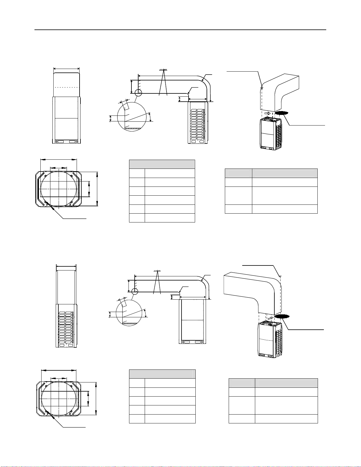
3 OutdoorUnitDuctingandShielding
3.1 DuctingRequirements
Dependingontheheightofadjacentwallsrelativetotheheightoftheunits,ductingmayberequiredtoensureproperair
discharge.InthesituationdepictedinFigure3‐3.1,theverticalsectionofductingshouldbeatleastH‐hhigh.
Figure3‐3.1:Top ofunitbelowtopofadjacentwall
3.2 DesignConsiderations
Outdoorunitductingdesignshouldtakeaccountofthefollowing:
Eachductshouldcontainnomorethanonebend.
Vibrationisolationshouldbeaddedtotheconnectionbetweentheunitandtheductingtoavoidvibration/noise.
Installinglouversisnotrecommendedasdoingsodecreasesairflow,impactinguponcooling/heatingperformance
andenergyefficiency.Iftheinstallationsituationnecessitateslouvers,theyshouldbeinstalledatananglenogreater
than15°tothehorizontal,tominimizetheimpactonairflow.
hh-H
H
Beforeinstallinganindoorunit,checkthatthemodeltobeinstalledisasspecifiedintheconstructiondrawings
andconfirmthecorrectorientationoftheunit.
Ensurethatunitsareinstalledatthecorrectheight.
Toallowsmoothcondensatedrainageandtoensureunitstability(topreventexcessivenoiseorvibration),
ensurethatunitsareleveltowithin1°ofthehorizontal.Ifaunitisnotleveltowithin1°ofthehorizontal,water
leakageorabnormalvibration/noisemayoccur.
Notesforinstallers

7
3.3 Ductingfor8HP,10HPand12HPUnits
3.3.1 OptionA–Transverseducting
Figure3‐3.2:Transverseductingfor8HP,10HPand12HPunits(unit:mm)
Table3‐3.1:Ductdimensions
Dimensions(mm)Table3‐3.2:Externalstaticpressure
AA≥300ESP(Pa)Remarks
BB≥2500Factorydefault
CC≤3000
0–20Removesteelmeshand
connecttoduct<3mlong
D731≤D≤770
EE=A+731>20Customizationoption
θ Θ≤15°
3.3.2 OptionB–Longitudinalducting
Figure3‐3.3:Longitudinalductingfor8HP,10HPand12HPunits(unit:mm)
Table3‐3.3:Ductdimensions
Dimensions(mm) Tab le3‐3.4:Externalstaticpressure
AA≥300ESP(Pa)Remarks
BB≥250
0Factorydefault
CC≤3000
0–20Removesteelmeshand
connecttoduct<3mlong
DD=A+750
θ Θ≤15°
>20Customizationoption
750
Support
Radius
Radius
Airoutletlouver(optional)
731
A
C
D
B
90
100
θ
E
750
340
320
704
8×φ3.3
731
Support
Radius
Radius
Airoutletlouver(optional)
750
A
C
B
90
100
θ
D
770
750
340
320
704
8×φ3.3
8×ST3.9self‐
threadingscrews
Removethe
steelmeshfirst
8×ST3.9self‐
threadingscrews
Removethe
steelmeshfirst

8
3.4 Ductingfor14HP,16HP,18HP,20HPand22HPUnits
3.4.1 OptionA–Transverseducting
Figure3‐3.4:Transverseductingfor14HP,16HP,18HP,20HPand22HPunits(unit:mm))
Table3‐3.5:Ductdimensions
Dimensions(mm)Table3‐3.6:Externalstaticpressure
AA≥300ESP(Pa)Remarks
BB≥2500Factorydefault
CC≤3000
0–20Removesteelmeshand
connecttoduct<3mlong
D630≤D≤660
EE=A+630>20Customizationoption
θ Θ≤15°
3.4.2 OptionB–Longitudinalducting
Figure3‐3.5:Longitudinalductingfor14HP,16HP,18HP,20HPand22HPunits(unit:mm)
Table3‐3.7:Ductdimensions
Dimensions(mm) Tab le3‐3.8:Externalstaticpressure
AA≥300ESP(Pa)Remarks
BB≥250
0Factorydefault
CC≤3000
0–20Removesteelmeshand
connecttoduct<3mlong
DD=A+1290
θ Θ≤15°
>20Customizationoption
1290
Support
Radius
Radius
Airoutletlouver(optional)
630
A
C
D
B
90
100
θ
E
1290
1020
300
320
12×φ3.3
630
630
Support
Radius
Radius
Airoutletlouver(optional)
1290
A
C
B
90
100
θ
D
1310
1290
1020
300
320
12×φ3.3
630
12 ×ST3.9self‐
threadingscrews
Removethe
steelmeshes
first
12 ×ST3.9self‐
threadingscrews
Removethe
steelmeshes
first

9
3.5 FanPerformance
Thedefaultexternalstaticpressureofoutdoorunits’airoutletsiszero.Withthesteelmeshcoverremovedtheexternal
staticpressureis20Pa.Withcustomizationoptions,externalstaticpressurecanbeincreasedto40Pa.
Figure3‐3.6:8HPand10HPunitsfanperformanceFigure3‐3.7:12HPunitsfanperformance
Figure3‐3.8:14HPand16HPunitsfanperformance
Figure3‐3.9:18HPunitsfanperformance
Figure3‐3.10:20HPand22HPunitsfanperformance
Staticpressure(Pa)
A
irvolume(m
3
/h)
10,800
11,000
11,200
11,400
11,600
11,800
12,000
12,200
0 1020304050
B:Customized
A:Default
Staticpressure(Pa)
Airvolume(m
3
/h)
B:Customized
A:Default
10,800
11,000
11,200
11,400
11,600
11,800
12,000
12,200
0 1020304050
Staticpressure(Pa)
Airvolume(m
3
/h)
13,200
13,400
13,600
13,800
14,000
14,200
14,400
14,600
0 1020304050
B:Customized
A:Default
Staticpressure(Pa)
Airvolume(m
3
/h)
15,750
15,800
15,850
15,900
15,950
16,000
16,050
16,100
0 1020304050
B:Customized
A:Default
Staticpressure(Pa)
Airvolume(m
3
/h)
01020304050
B:Customized
A:Default
14,600
14,800
15,000
15,200
15,400
15,600
15,800
16,000
16,200
Beforeinstallingoutdoorunitducting,besureto
removetheunit’ssteelmeshcover,otherwiseairflow
willbeadverselyaffected.
Notesforinstallers

10
3.6 SnowShielding
Inareasofhighsnowfall,snowshieldsshouldbeinstalledonairinletsandoutletstopreventsnowfromenteringtheunits.
Additionally,theheightofthebasestructuresshouldbeincreasedsoastoraisetheunitsfurtherofftheground.
Figure3‐3.11:Outdoorunitsnowshielding
4 RefrigerantPipingDesign
4.1 DesignConsiderations
Refrigerantpipingdesignshouldtakeaccountofthefollowingconsiderations:
Theamountofbrazingrequiredshouldbekepttoaminimum.
Onthetwoinsidesidesofthefirstindoorbranchjoint(“A”inFigures3‐4.2and3‐4.3)thesystemshould,asfaras
possible,beequalintermsofnumberofunits,totalcapacitiesandtotalpipinglengths.
4.2 MaterialSpecification
Onlyseamlessphosphorus‐deoxidizedcopperpipingthatcomplieswithallapplicablelegislationshouldbeused.Temper
gradesandminimumthicknessesfordifferentdiametersofpipingarespecifiedinTable3‐4.1.
Table3‐4.1:Pipingtemperandthickness
Pipingouterdiameter
(mm)Temper1Minimumthickness
(mm)
Ф6.35
O
(annealed)
0.8
Ф9.530.8
Ф12.70.8
Ф15.91.0
Ф19.11.0
Ф22.2
1/2H
(halfhard)
1.2
Ф25.41.2
Ф28.61.3
Ф31.81.5
Ф38.11.5
Ф41.31.5
Ф44.51.5
Ф54.01.8
Notes:
1. O:coiledpiping;1/2H:straightpiping.
Snow shield for air outle
t
Snow shield for air inlet

11
4.3 PermittedPipingLengthsandLevelDifferences
ThepipinglengthandleveldifferencerequirementsthatapplyaresummarizedinTable3‐4.3andarefullydescribedas
follows(refertoFigure3‐4.2):
1. Requirement1:Thetotallengthofpipinginonerefrigerantsystemshouldnotexceed1000m.Whencalculatingthe
totallengthofpiping,theactuallengthoftheindoormainpipes(thepipingbetweenthefirstindoorbranchjointand
allotherindoorbranchjoints,L2toL12)shouldbedoubled.
2. Requirement2:Thepipingbetweenthefarthestindoorunit(N9)andthefirstoutdoorbranchjoint(N)shouldnot
exceed175m(actuallength)and200m(equivalentlength).(Theequivalentlengthofeachbranchjointis0.5m.)
3. Requirement3:Thepipingbetweenthefarthestindoorunit(N9)andfirstindoorbranchjoint(A)shouldnotexceed
40minlength(Ʃ{L7toL10}+i≤40m)unlessthefollowingconditionsaremetandthefollowingmeasurestaken,in
whichcasethepermittedlengthisupto90m:
Conditions:
a) Eachindoorauxiliarypipe(fromeachindoorunittoitsnearestbranchjoint)jointdoesnotexceed40minlength
(atomeach≤40m).
b) Thedifferenceinlengthbetween{thepipingfromfirstindoorbranchjoint(A)tothefarthestindoorunit(N9)}
and{thepipingfromthefirstindoorbranchjoint(A)tothenearestindoorunit(N1)}doesnotexceed40m.That
is:(Ʃ{L7toL10}+i)‐(Ʃ{L2toL3}+a) ≤ 40m.
Measures:
a) Increasethediameteroftheindoormainpipes(thepipingbetween
thefirstindoorbranchjointandallotherindoorbranchjoints,L2to
L12)asperTable3‐4.2,exceptforindoormainpipeswhichare
alreadythesamesizeasthemainpipe(L1),forwhichnodiameter
increasesarerequired.
4. Requirement4:Thelargestleveldifferencebetweenindoorunitand
outdoorunitshouldnotexceed90m(iftheoutdoorunitisabove)or
110m(iftheoutdoorunitisbelow).Additionally:(i)Iftheoutdoorunitis
aboveandtheleveldifferenceisgreaterthan20m,itisrecommended
thatanoilreturnbendwithdimensionsasspecifiedinFigure3‐4.1isset
every10minthegaspipeofthemainpipe;and(ii)iftheoutdoorunitis
belowandtheleveldifferenceismorethan40m,theliquidpipeofthe
mainpipe(L1)shouldbeincreasedasperTable3‐4.2.
5. Requirement5:Thelargestleveldifferencebetweenindoorunitsshould
notexceed30m.
Table3‐4.2:Diameterincreaserequirements
Original(mm)Increased(mm)
Φ
9.53
Φ
12.7
Φ12.7Φ15.9
Φ15.9Φ19.1
Φ
19.1
Φ
22.2
Φ22.2Φ25.4
Φ25.4Φ28.6
Φ
28.6
Φ
31.8
Φ31.8Φ38.1
Φ38.1Φ41.3
Φ
41.3
Φ
44.5
Φ44.5Φ54.0
Figure3‐4.1:Oilreturnbend(unit:mm)
300
ormore
300
ormore

12
Figure3‐4.2:Permittedrefrigerantpipinglengthsandleveldifferences
Table3‐4.3:Summaryofpermittedrefrigerantpipinglengthsandleveldifferences
PermittedvaluesPipinginFigure3‐4.2
Pipinglengths
Totalpipinglength1≤1000mL1+2xƩ{L2toL12}+Ʃ{atom}
Pipingbetweenfarthestindoor
unitandfirstoutdoorbranch
joint2
Actuallength≤175m
L1+Ʃ{L7toL10}+i
Equivalent
length≤200m
Pipingbetweenfarthestindoorunitandfirst
indoorbranchjoint3≤40m/90mƩ{L7toL10}+i
Level
differences
Largestleveldifferencebetween
indoorunitandoutdoorunit4
Outdoorunitis
above≤90m
Outdoorunitis
below≤110m
Largestleveldifferencebetweenindoorunits5≤30m
Notes:
1. RefertoRequirement1,above.
2. RefertoRequirement2,above.
3. RefertoRequirement3,above.
4. RefertoRequirement4,above.
5. RefertoRequirement5,above.
Firstindoor
branchjoint
Largestleveldifferencebetweenindoor
unitandoutdoorunitH≤90m
LargestleveldifferencebetweenindoorunitsH≤30m
Pipingbetween farthestindoorunitandfirstindoorbranchjointL≤40m
Equivalentlengthofpipingbetween farthestindoorunit
andfirstoutdoorbranchjointL≤200m
N
1
(140)
N
4
(140)
N
7
(140)
N
8
(140)
N
10
(28)
N
12
(56)
N
11
(140)
N
3
(71)
N
6
(28)
N
13
(56)
A
B
GH
K
I
L
C
E
L
1
L
2
L
3
L
5
L
7
L
8
L
11
L
12
L
9
a
c
d
f
gh
j
lm
k
MN
g1 g2 g3
G
1
12HP 12HP 22HP
D
N
2
(140)
b
L
4
N
5
(140)
F
L
6
e
N
9
(71)
i
J
L
10
Legend
L1Mainpipe
Figuresinparentheses
indicateindoorunit
capacityindexes.
L2toL12Indoormainpipes
atomIndoorauxiliarypipes
AtoLIndoorbranchjoints
M,NOutdoorbranchjoints
g1tog3,G1Outdoorconnectionpipes

13
4.4 SelectingPipingDiameters
Tables3‐4.4to3‐4.8,below,specifytherequiredpipediametersfortheindoorandoutdoorpiping.Themainpipe(L1)and
firstindoorbranchjoint(A)shouldbesizedaccordingtowhicheverofTables 3‐4.4and3‐4.5indicatesthelargersize.
Figure3‐4.3:Selectingpipingdiameters
Tab le3‐4.4:Mainpipe1(L1),indoormainpipes(L2toL12)andindoorbranchjointkits
Totalcapacityofindoorunits(kW)Gaspipe(mm)Liquidpipe(mm)Branchjointkit
Capacity<16.6Φ15.9
Capacity<23Φ19.1Φ9.53FQZHN‐01D
23≤Capacity<33Φ22.2Φ9.53FQZHN‐02D
33≤Capacity<46Φ28.6Φ12.7FQZHN‐03D
46≤Capacity<66Φ28.6Φ15.9FQZHN‐03D
66≤Capacity<92Φ31.8Φ19.1FQZHN‐03D
92≤Capacity<135Φ38.1Φ19.1FQZHN‐04D
135≤Capacity<180Φ41.3Φ22.2FQZHN‐05D
180≤Capacity Φ44.5Φ25.4FQZHN‐05D
Notes:
1. Themainpipe(L1)andfirstindoorbranchjoint(A)shouldbesizedaccordingtowhicheverofTables3‐4.4
and3‐4.5indicatesthelargersize.
N
1
(140)
N
4
(140)
N
7
(140)
N
8
(140)
N
10
(28)
N
12
(56)
N
11
(140)
N
3
(71)
N
6
(28)
N
13
(56)
A
B
GH
K
I
L
C
E
L
1
L
2
L
3
L
5
L
7
L
8
L
11
L
12
L
9
a
c
d
f
gh
j
lm
k
MN
g1 g2 g3
G
1
12HP 12HP 22HP
D
N
2
(140)
b
L
4
N
5
(140)
F
L
6
e
N
9
(71)
i
J
L
10
Firstindoor
branchjoint
Alternativeoutdoorunitarrangements
Mainpipe
M
g1 g2
MNO
G
2
G
1
Mainpipe
g1 g2 g3 g4
Legend
L1Mainpipe
Figuresinparentheses
indicateindoorunit
capacityindexes.
L2toL12 Indoormainpipes
atomIndoorauxiliarypipes
AtoLIndoorbranchjoints
MtoOOutdoorbranchjoints
g1tog4,G1,G2Outdoorconnectionpipes
Φ9.53FQZHN‐01D
16.6≤
7
7
7
7
7
7
7
7
7

14
Tab le3‐4.5:Mainpipe1(L1)andfirstindoorbranchjoint(A)
Totalcapacityof
outdoorunits
Equivalentlengthofallliquidpipes<90mEquivalentlengthofallliquidpipes≥90m
Gaspipe(mm)Liquidpipe(mm)BranchjointkitGaspipe(mm)Liquidpipe(mm)Branchjointkit
8HPΦ22.2Φ9.53FQZHN‐02DΦ22.2
Φ9.53FQZHN‐02DΦ25.4Φ12.7FQZHN‐02D
12‐14HPΦ25.4Φ12.7FQZHN‐02DΦ28.6Φ15.9FQZHN‐03D
16HPΦ28.6Φ12.7FQZHN‐03DΦ31.8Φ15.9FQZHN‐03D
18‐22HPΦ28.6Φ15.9FQZHN‐03DΦ31.8Φ19.1FQZHN‐03D
24HPΦ28.6Φ15.9FQZHN‐03DΦ31.8Φ19.1FQZHN‐03D
26‐34HPΦ31.8Φ19.1FQZHN‐03DΦ38.1Φ22.2FQZHN‐04D
36‐50HPΦ38.1Φ19.1FQZHN‐04DΦ38.1Φ22.2FQZHN‐04D
52‐66HPΦ41.3Φ22.2FQZHN‐05DΦ44.5Φ25.4FQZHN‐05D
68‐88HPΦ44.5Φ25.4FQZHN‐05DΦ54.0Φ25.4FQZHN‐06D
Notes:
1. Themainpipe(L1)andfirstindoorbranchjoint(A)shouldbesizedaccordingtowhicheverofTabl es3‐4.4and3‐4.5indicatesthelargersize.
Table3‐4.6:Outdoorconnectionpipes(g1tog4,G1,G2)Table3‐4.7:Outdoorbranchjointkits(NtoO)
PipesOutdoorunit
capacityGaspipe(mm)Liquidpipe(mm)No.ofoutdoor
unitsBranchjointkit
g1tog4
8‐12HPΦ25.4Φ12.7 2FQZHW‐02N1D
14‐22HPΦ31.8Φ15.9 3FQZHW‐03N1D
G1 Φ38.1Φ19.1 4FQZHW‐04N1D
G2 Φ41.3Φ22.2
Table3‐4.8:Indoorauxiliarypipes(atom)
Capacityofindoorunit
(kW)
Pipelength≤10mPipelength>10m1
Gaspipe(mm)Liquidpipe(mm)Gaspipe(mm)Liquidpipe(mm)
≤4.5Φ12.7Φ6.35Φ15.9Φ9.53
≥5.6Φ15.9Φ9.53Φ19.1Φ12.7
Notes:
1. Anindoorauxiliarypipeshouldnotbelargerthantheindoormainpipeimmediatelyupstreamofit.Forindoorauxiliary
pipesgreaterthan10minlengthwithindoorunitsofcapacitygreatthanorequalto5.6kW,thegasandliquidsidepipes
shouldeacheitherbesizedaccordingtothistable,orelsebethesamesizeastheindoormainpipeimmediately
upstream,whicheverissmaller.
Φ12.7FQZHN‐02D
10HPΦ22.2
7
7
7
7
7
7
7
7
7
7
7
7
7
7
7
7
7
7
7
7
7
7
7

15
4.5 RefrigerantPipingSelectionExample
Theexamplebelowillustratesthepipingselectionprocedureforasystemconsistingofthreeoutdoorunits(22HP+12HP+
12HP)and13indoorunits.Thesystem'sequivalenttotalpipinglengthisinexcessof90m;thepipingbetweenthe
farthestindoorunitandthefirstindoorbranchjointislessthan40minlength;andeachindoorauxiliarypipe(fromeach
indoorunittoitsnearestbranchjoint)islessthan10minlength.
Figure3‐4.4:Refrigerantpipingselectionexample
Step1:Selectindoorauxiliarypipes
IndoorunitsN1toN5,N7toN9andN11toN13areofcapacity5.6kWorgreaterandtheirindoorauxiliarypipesareless
than10minlength.RefertoTable3‐4.8.Indoorauxiliarypipesatoe,gtoi,andktomareΦ15.9/Φ9.53.
IndoorunitsN6andN10areofcapacitylessthan4.5kWandtheirindoorauxiliarypipesarelessthan10minlength.
RefertoTable3‐4.8.IndoorauxiliarypipesfandjareΦ12.7/Φ6.35.
Step2:SelectindoormainpipesandindoorbranchjointsBtoL
Theindoorunits(N2andN3)downstreamofindoorbranchjointDhavetotalcapacityof14+7.1=21.1kW.Referto
Table3‐4.4.IndoormainpipeL4isΦ19.1/Φ9.53.IndoorbranchjointDisFQZHN‐01D.
Theindoorunits(N1toN6)downstreamofindoorbranchjointBhavetotalcapacityof14x4+7.1+2.8=65.9kW.
RefertoTable3‐4.4.IndoormainpipeL2isΦ28.6/Φ15.9.IndoorbranchjointBisFQZHN‐03D.
TheotherindoormainpipesandindoorbranchjointsCandEtoLareselectedinthesamefashion.
Step3:SelectmainpipeandindoorbranchjointA
Theindoorunits(N1toN13)downstreamofindoorbranchjointAhavetotalcapacityof14x7+7.1x2+5.6x2+2.8
x2=129kW.Thesystem'sequivalenttotalpipinglengthisinexcessof90m.Thetotalcapacityoftheoutdoorunitsis
22+12+12=46HP.RefertoTables3‐4.4and3‐4.5.MainpipeL1isthelargerofΦ38.1/Φ19.1andΦ38.1/Φ22.2,
henceΦ38.1/Φ22.2.IndoorbranchjointAisFQZHN‐04D.
Step4:Selectoutdoorconnectionpipesandoutdoorbranchjoints
Themasterunitis22HPandtheslaveunitsare12HP.RefertoTable3‐4.6.Outdoorconnectionpipesg1andg2are
Φ25.4/Φ12.7andoutdoorconnectionpipeg3isΦ31.8/Φ15.9.
RefertoTable3‐4.6.OutdoorconnectionpipeG1isΦ38.1/Φ19.1.
N
1
(140)
N
4
(140)
N
7
(140)
N
8
(140)
N
10
(28)
N
12
(56)
N
11
(140)
N
3
(71)
N
6
(28)
N
13
(56)
A
B
GH
K
I
L
C
E
L
1
L
2
L
3
L
5
L
7
L
8
L
11
L
12
L
9
a
c
d
f
gh
j
lm
k
MN
g1 g2 g3
G
1
12HP 12HP 22HP
D
N
2
(140)
b
L
4
N
5
(140)
F
L
6
e
N
9
(71)
i
J
L
10
Firstindoor
branchjoint
Legend
L1Mainpipe
L2toL12Indoormainpipes
atomIndoorauxiliarypipes
AtoLIndoorbranchjoints
M,NOutdoorbranchjoints
g1tog3,G1Outdoorconnectionpipes
Figuresinparenthesesindicateindoorunit
capacityindexes.

16
Therearethreeoutdoorunitsinthesystem.RefertoTable3‐4.7.OutdoorbranchjointsMandNareTFQZHW‐03N1D.

17
4.6 BranchJoints
Branchjointdesignshouldtakeaccountofthefollowing:
U‐shapedbranchjointsshouldbeused–teejointsarenotsuitable.BranchjointdimensionsaregiveninTables3‐4.9
and3‐4.10.
Toavoidaccumulationofoilintheoutdoorunits,outdoorbranchjointsshouldbeinstalledhorizontallyandmustnot
behigherthantheoutdoorunitrefrigerantoutlets.RefertoFigure3‐5.9inInstallationManual,5.6“BranchJoints”.
Indoorbranchjointsmaybeinstalledeitherhorizontallyorvertically.
Toensureevendistributionofrefrigerant,branchjointsshouldnotbeinstalledwithin500mmofa90°bend,another
branchjointorthestraightsectionofpipingleadingtoanindoorunit,withtheminimum500mmbeingmeasured
fromthepointwherethebranchjointisconnectedtothepiping,asshowninFigure3‐4.5.
Figure3‐4.5:Branchjointspacingandseparationfrombends(unit:mm)
500ormore500ormore500ormore
500ormore500ormore
Indoor
unit
Indoor
unit
Indoor
unit

18
Table3‐4.9:Indoorbranchjointdimensions(unit:mm)
ModelGassidejointsLiquidsidejoints
TFQZHN‐01D
TFQZHN‐02D
TFQZHN‐03D
TFQZHN‐04D
TFQZHN‐05D
TFQZHN‐06D
ID:12.7
(ID:15.9)
OD:19.1
ID:19.1
OD:19.1
ID:19.1
ID:15.9
ID:12.7
(ID:15.9)
OD:19.1
OD:12.7
ID:9.5
ID:9.5
ID:6.4
OD:9.5
ID:6.4
OD:9.5
ID:9.5
ID:15.9
(ID:19.1)
OD:22.2
ID:22.2
OD:22.2
ID:22.2
ID:25.4
ID:15.
9
(ID:19.1)
OD:22.2
ID:12.7
OD:12.7
ID:6.4
ID:9.5
OD:12.7
OD:12.7
ID:12.7
ID:9.5
ID:12.7
ID:6.
4
ID:9.5
ID:28.6
ID:31.8
OD:28.6
ID:28.6
ID:19.1
ID:22.2
OD:28.6
ID:19.1
ID:22.2
OD:28.6
ID:15.
9
ID:15.9
OD:15.9
ID:19.1
(ID:12.7)
OD:15.9
ID:9.5
ID:15.9
(ID:12.7)
OD:15.9
ID:9.5
ID:6.4
ID:19.1
ID:22.2
ID:28.6
OD:34.9
ID:34.9
OD:34.9
ID:38.1
ID:22.2
ID:28.6
OD:34.9
ID:34.9
ID:12.7
(ID:15.9)
OD:19.1
ID:19.1
OD:19.1
ID:19.1
ID:22.2
ID:12.7
(ID:15.9)
OD:19.1
ID:9.5
ID:34.9
ID:41.3
ID:34.9
ID:41.3
ID:41.3
ID:44.5
ID:44.5
OD:41.3
ID:15.9
(ID:19.1)
OD:22.2
ID:22.2
OD:22.2
ID:22.2
ID:25.4
ID:15.9
(ID:19.1)
OD:22.2
ID:12.7
ID:54
ID:34.9
ID:41.3
ID:63.5
ID:54
OD:54
OD:54
ID:41.3
ID:63.5
ID:15.9
(ID:19.1)
OD:22.2
ID:22.2
(ID:19.1)
OD:22.2
ID:22.2
ID:25.4
ID:25.4
OD:22.2

19
Table3‐4.10:Outdoorbranchjointdimensions(unit:mm)
ModelGassidejointsLiquidsidejoints
TFQZHW‐02N1D
TFQZHW‐03N1D
TFQZHW‐04N1D
0D:31.8
ID:25.4
0D:31.8
ID:31.8
ID:25.4
Q1
Q2
ID:34.9
ID:31.8
ID:31.8
Q4
0D:34.9
ID:38.1
ID:34.9
Q3
ID:19.1
ID:15.9
ID:15.9
Y6
ID:15.9 0D:15.9
ID:12.7
ID:12.7
0D:15.9
Y1
Y2
0D:19.1
ID:22.2
ID:19.1
Y3
ID:31.8
0D:34.9
ID:31.8 ID:38.1
ID:34.9
0D:31.8
ID:25.4
0D:31.8
ID:31.8
ID:25.4
Q1
Q2 Q7
ID:38.1
ID:41.3
ID:31.8
0D:31.8
ID:31.8
ID:25.4
Q1
Q5
ID:15.9
ID:15.9
ID:19.1
ID:15.9
0D:15.9
ID:12.7
ID:12.7
0D:15.9
Y1
Y6
Y2
ID:19.1 ID:22.2
ID:15.9
0D:15.9
ID:15.9
ID:12.7
Y1
Y7
0D:22.2
ID:19.1
Y4
ID:31.8
0D:34.9
ID:31.8 ID:38.1
ID:34.9
0D:31.8
ID:25.4
0D:31.8
ID:31.8
ID:25.4
Q1
Q2 Q7
ID:38.1
ID:41.3
ID:31.8
0D:31.8
ID:31.8
ID:25.4
Q1
Q5
ID:41.3
ID:44.5
ID:31.8
0D:31.8
ID:31.8
ID:25.4
Q1
Q6
Description
ID:15.9
ID:19.1
ID:15.9
ID:15.9
0D:15.9
ID:12.7
ID:12.7
0D:15.9
Y1
Y6
Y2
ID:19.1 ID:22.2
ID:15.9
0D:15.9
ID:15.9
ID:12.7
Y1
Y7
ID:25.4
ID:22.2
ID:15.9
0D:15.9
ID:15.9
ID:12.7
Y1
Y8
0D:25.4
ID:22.2
Y5
Table of contents
Popular Inverter manuals by other brands

V-TAC
V-TAC 80133970 instruction manual

Clenergy
Clenergy PV-ezRack SolarFloating I installation guide

Selectronic
Selectronic WM1400-12V owner's manual

Mitsubishi Electric
Mitsubishi Electric FR-F700 Series instruction manual

Philips
Philips ELI-S-20 installation instructions

Endress
Endress ESE 607 DBG ES DIN operating manual