TRUWEO TRU010005N User manual
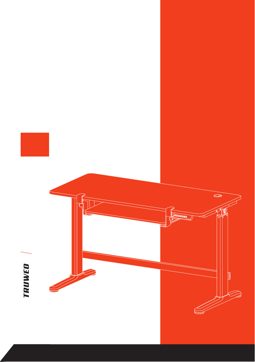
ELECTRIC
STANDING
DESK
DESKTOP
MANUAL
1
YEAR
WARRANTY

In the event this product malfunctions or you believe
it is defective, please contact Customer Service
at 1(347)841-0317 or support@truweo.com and
hold onto the defective product (pending further
instruction). A defective product should be clearly
marked or stored in a place where it cannot be
used by mistake. Failure to keep the product in its
original quality from the time of receipt may impede
TRUWEO’s ability to correct any legitimate problem
and may limit the extent to which TRUWEO may
provide recourse.
ATTENTION

IMPORTANT SAFETY INFORMATION
LIST OF PARTS
ASSEMBLY INSTRUCTIONS
OPERATION
TROUBLESHOOTING
CLEANING AND MAINTENANCE
WARRANTY
CONTACT US
5
7
10
22
24
25
25
26
TABLE OF CONTENTS

ELECTRIC STANDING DESK
5
IMPORTANT SAFETY INFORMATION
WARNING!
IMPORTANT SAFETY INSTRUCTIONS! SAVE THESE INSTRUCTIONS!
• Basic safety precautions should always be followed. PLEASE READ ALL
INSTRUCTIONS BEFORE USING YOUR ELECTRIC STANDING DESK.
DANGER
To reduce the risk of electrical shock:
• Always unplug this unit from the electrical outlet before cleaning.
Risk of suocation!
• Keep all packaging materials away from children as these materials pose a
suocation risk or other harm.
WARNING!
To reduce the risk of burns, re, electrical shock, or injury:
• Unplug the unit before assembling or disassembling parts.
• Exercise caution and provide supervision when operating this unit in the presence of
children, the elderly, or anyone with physical or mental incapacity. Children should
not play with this device.
• Operate this unit only for its intended as purpose described in this manual. Do not
use attachments that are not recommended by the manufacturer.
• Do not operate the unit if the power cord is damaged, or if the unit malfunctions or is
dropped in any way. Contact Customer Service for inspection, repair, or replacement.
• Keep the power cord away from heated surfaces.
• Do not operate the unit if the air openings are blocked. Keep the air openings free of
debris or obstructions (e.g. lint, hair, dust, etc.).
• Do not drop or insert any objects into the openings.
• This unit is only meant for indoor use. Do not use it outdoors.
• Do not operate the unit in an area where aerosol spray products are being used or
oxygen is being administered.
• To disconnect the unit, turn all controls to the OFF position, then remove the power
cord from the outlet.
• When loading, always put heavier items at the bottom and avoid placing them near
the top of the unit to prevent the unit from tipping over.
• If the desktop is not mounted to the table correctly, it could cause the whole unit to be
unstable. The unit may collapse and cause the electrical components to fail.
• Mount the unit at the correct height.
• WARNING! Risk of re or shock! Only use the SJT type 18 AWG cord near to the
power inlet.
• WARNING! Risk of injury! Do not overload the desktop (110 lbs) or the keyboard (4.4lbs).

ELECTRIC STANDING DESK
6
FCC STATEMENT
This device complies with part 15 of the FCC Rules. Operation is subject to the
following two conditions: (1) this device may not cause harmful interference, and
(2) this device must accept any interference received, including interference that
may cause undesired operation.
This equipment has been tested and found to comply with the limits for a ClassB
digital device, pursuant to part 15 of the FCC Rules. These limits are designed
to provide reasonable protection against harmful interference in a residential
installation. This equipment generates, uses, and can radiate radio frequency
energy and, if not installed and used in accordance with the instructions, may cause
harmful interference to radio communications. However, there is no guarantee that
interference will not occur in a particular installation. If this equipment does cause
harmful interference to radio or television reception, which can be determined
by turning the equipment o and on, the user is encouraged to try to correct the
interference by one or more of the following measures:
• Reorient or relocate the receiving antenna.
• Increase the separation between the equipment and receiver.
• Connect the equipment into an outlet on a circuit dierent from that to which the
receiver is connected.
• Consult the dealer or an experienced radio/TV technician for help.
MODIFICATION: Any changes or modications not expressly approved by the
grantee of this device could void the user’s authority to operate the device.
BEFORE FIRST USE IMPORTANT
Load capacity: 110 Lb
Keyboard tray load:Max 4.4Lb
Adjustable height: 29.1–47.5 Inch
Power input: 1.5 A, AC 120 V, 60 Hz
SPECIFICATIONS
Keep for future reference. Read carefully.
Before rst use:
• Check the product for damage during
transport.
• Remove all packing materials.

ELECTRIC STANDING DESK
7
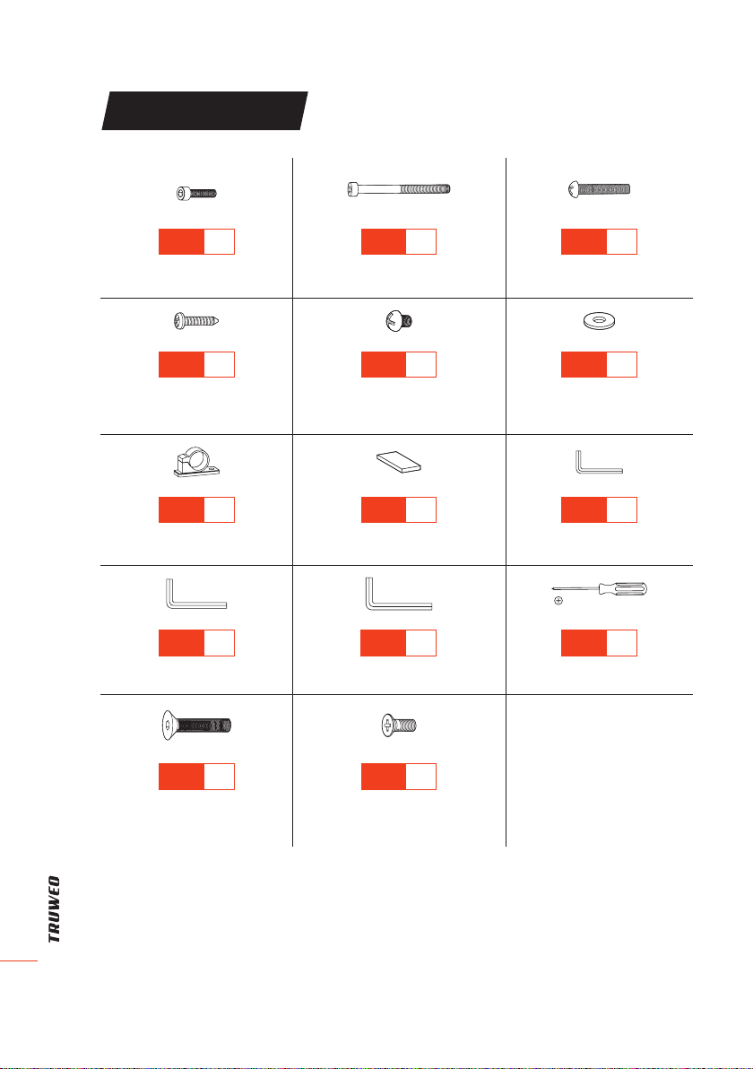
LIST OF PARTS
TIP
Count and inspect all parts before assembly. If anything is
missing or damaged, please contact us immediately for a
quick and free replacement: support@truweo.com
A× 1
Connecting Bar
(Column to Motor)
B× 1
Motor
C× 2
Lifting Column
D× 1
Desktop
E× 1
Sync Rod
F× 1
Top Crossbar
G× 1
Adapter Holder
H× 1
AC Adapter
I× 1
Bottom Crossbar
J× 1
Power Cord
K× 1
Controller
L× 2
Side Bracket
M× 1
Mounting Clamp
(For Keyboard Tray)
N× 1
Mounting Clamp
(For Keyboard Tray)
O× 1
Keyboard Tray
ELECTRIC STANDING DESK
8
LIST OF PARTS
S-A × 4
Hex Head Screw
S-B × 4
Hex Head Screw
S-C × 6
Phillips Head Screw
S-D × 2
Phillips Head Screw
(For the Controller)
S-E × 4
Phillips Head Screw
S-F × 6
Washer
S-G × 3
Cable Clip
S-H × 9
Silicone Pad
S-I × 1
4 mm Allen Wrench
S-J × 1
5 mm Allen Wrench
S-K × 1
8 mm Allen Wrench
S-L × 1
Phillips Screwdriver
S-M × 4
Hex Head Screw
S-N × 4
Phillips Head Screw
(For Keyboard Tray)
ELECTRIC STANDING DESK
9
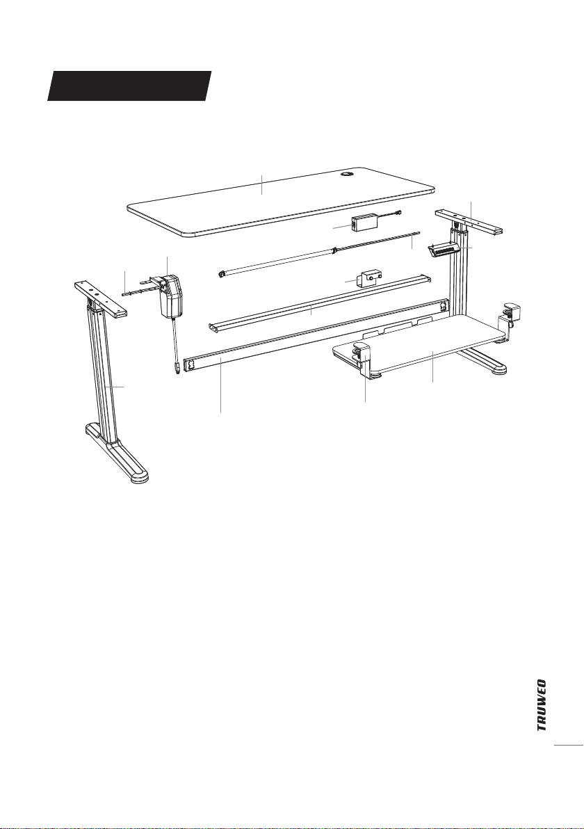
LIST OF PARTS
Desktop
Sync Rod Controller
AC Adapter
Crossbar
Adapter Holder
Motor
Connecting Bar
(Column to Motor)
Lifting Column
Crossbar
Keyboard Tray
Mounting Clamp
Side Bracket
ELECTRIC STANDING DESK
10
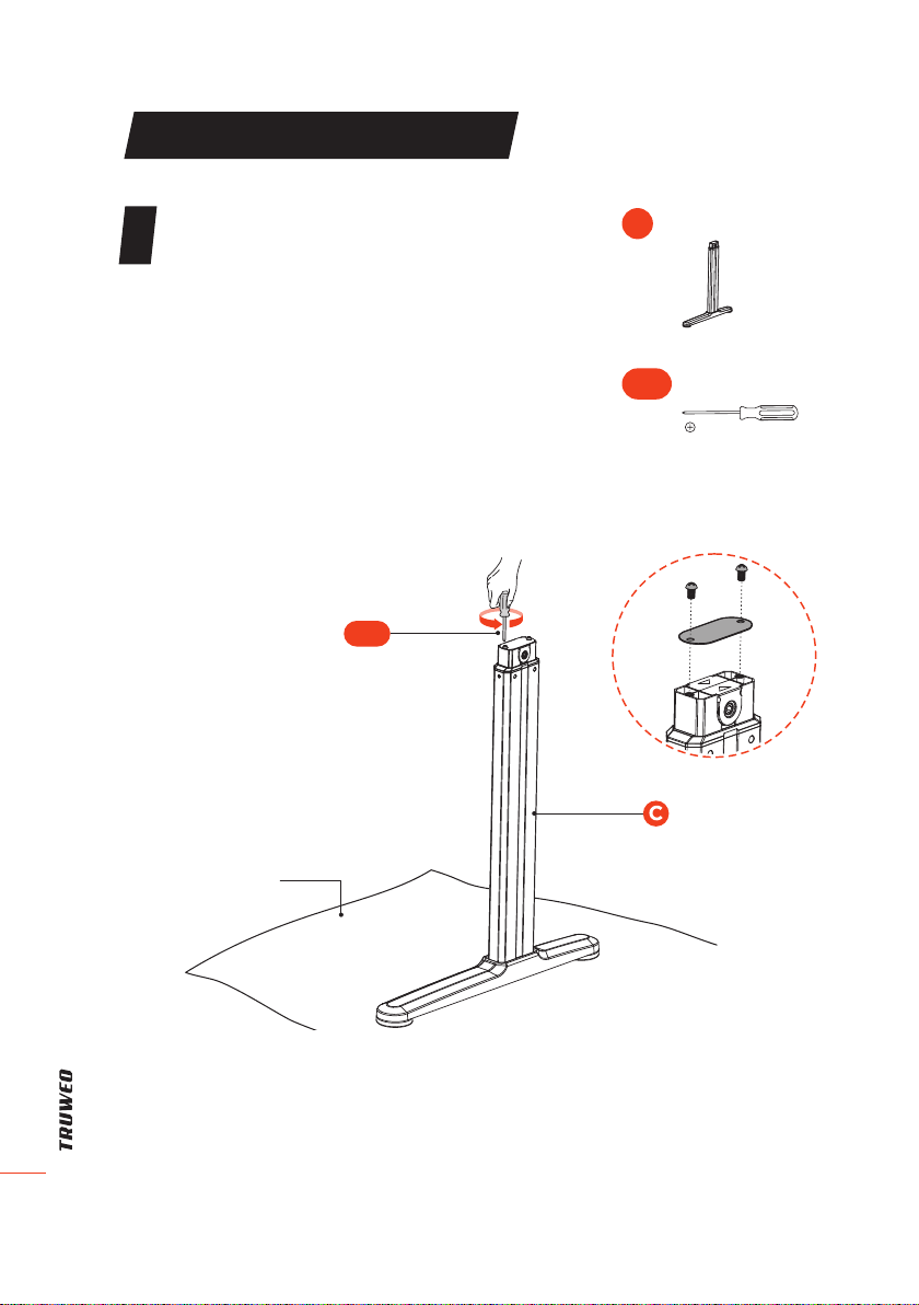
ASSEMBLY INSTRUCTIONS
Prepare the Lifting Columns
• Prepare an area with adequate space for
installation. Put a blanket on the area to
prevent scratches to the oor and the
desk.
• Remove the two screws on the top of the
Lifting Columns (C) using the Phillips
Screwdriver (S-L). Remove the protective
steel plate on the lifting columns.
Phillips Screwdriver
S-L
1
S-L
Blanket
(Not included
Lifting Column × 2
C
ELECTRIC STANDING DESK
11
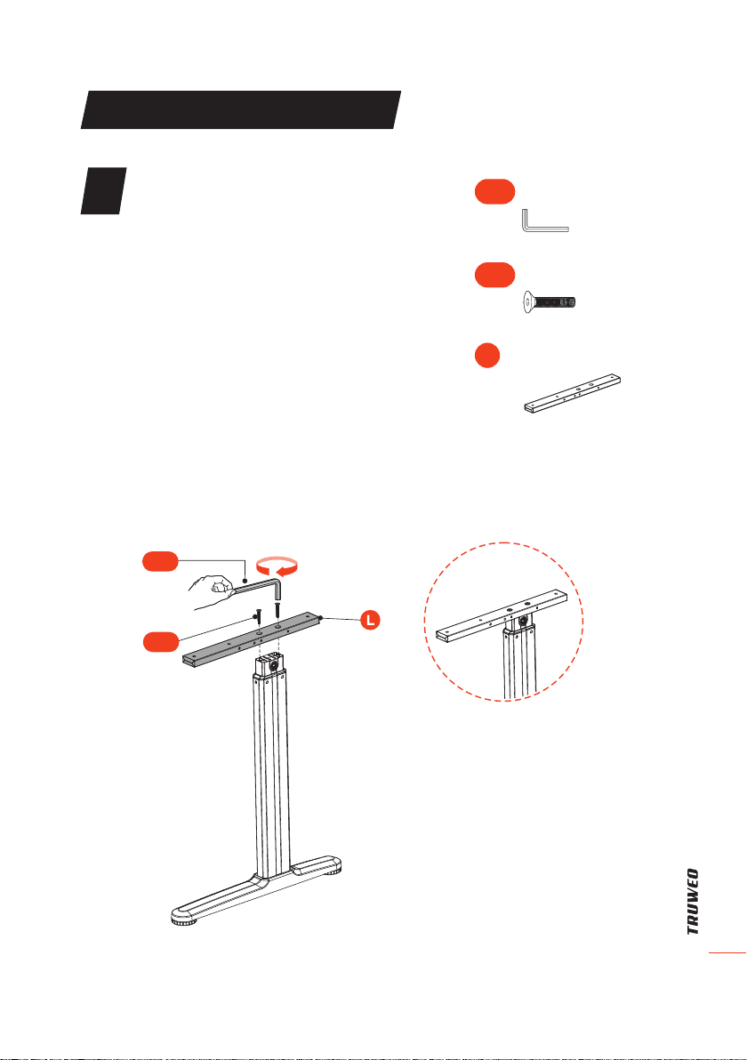
ASSEMBLY INSTRUCTIONS
2Attach the Side Brackets
• Attach the Side Brackets (L) to the
left and right Lifting Columns using
4Screws (S-M). Make sure the longer
end of the Side Brackets is facing
toward the front of the desk and in the
same direction as the lifting column.
Note:
• Attach the side brackets as shown in the
illustration. Make sure the side brackets
are not attached upside down.
S-I
S-M
4 mm Allen Wrench
S-I
Hex Head Screw × 4
S-M
Side Bracket x 2
L

ELECTRIC STANDING DESK
12
ASSEMBLY INSTRUCTIONS
Attach the Motor to the Lifting Columns
• Attach three Silicone Pads (S-H) to each
Side Bracket on the Lifting Columns.
• Insert the left end of Connecting Bar(A) to
the hex socket shaped mounting hole on
the Lifting Column(C).
• Insert the hex socket shaped mounting
hole on the Motor (B) to the right end of
Connecting Bar (A).
• Pass the Motor (B) through the
Connecting Bar (A) and attach it to the
Lifting Column with 2 Screws (S-E) from
the side of the column and with the other
2 Screws (S-E) from the bottom using the
Phillips Screwdriver (S-L).
Note:
• If the mounting hole on the lifting Column
cannot align to the connecting bar, adjust
the mounting hole using the 8 mm Allen
Wrench (S-K).
S-H
S-K
S-L
S-L
Silicone Pad × 6
S-H
Connecting Bar
Left Right
A
8 mm Allen Wrench
S-K
Motor
B
Phillips Head
Screw × 4
S-E
Phillips Screwdriver
S-L
3
Left Right

ELECTRIC STANDING DESK
13
ASSEMBLY INSTRUCTIONS
4Assemble the Adapter Holder(G) and
the Crossbar (F)
• Attach 3 Silicone Pads (S-H) to the
crossbar. Ensure that the side with the
pads is facing against the desktop.
• Attach the Crossbar (F) to the two
assembled lifting columns and tighten
the Screws (S-B) using the 4 mm Allen
Wrench (S-I).
• Attach the AC Adapter(H) and Adapter
Holder(G) to the Crossbar on the side
near the hand controller.
S-B
H
G
F
S-H
S-I
Crossbar
F
Silicone Pad × 3
S-H
Adapter Holder
G
AC Adapter
H
Hex Head Screw × 4
S-B
4 mm Allen Wrench
S-I

ELECTRIC STANDING DESK
14
ASSEMBLY INSTRUCTIONS
Assemble the Sync Rod
• Loosen the knob at the left side of the Sync Rod (E). Attach the
Sync Rod (E) to the motor spindle (Connecting Bar)and tighten the
knob securely (See Figure 1).
• Loosen the knob at the right side of the Sync Rod (E) and pull out
the inner bar to match the desktop length.
• Insert the inner bar of the Sync Rod (E) into the hex socket shaped
mounting hole on the Lifting Column until the red line rubber is
inside the hole (See Figure 2). Tighten the knob securely.
Note: If needed, adjust the mounting hole on the lifting column to align
with the sync rod using the 8mm Allen Wrench (S-K).
5
S-K
Figure 2
Loosen
Figure 1
Loosen
Sync Rod
Left Side
Right Side
E
8 mm Allen
Wrench
S-K
ELECTRIC STANDING DESK
15
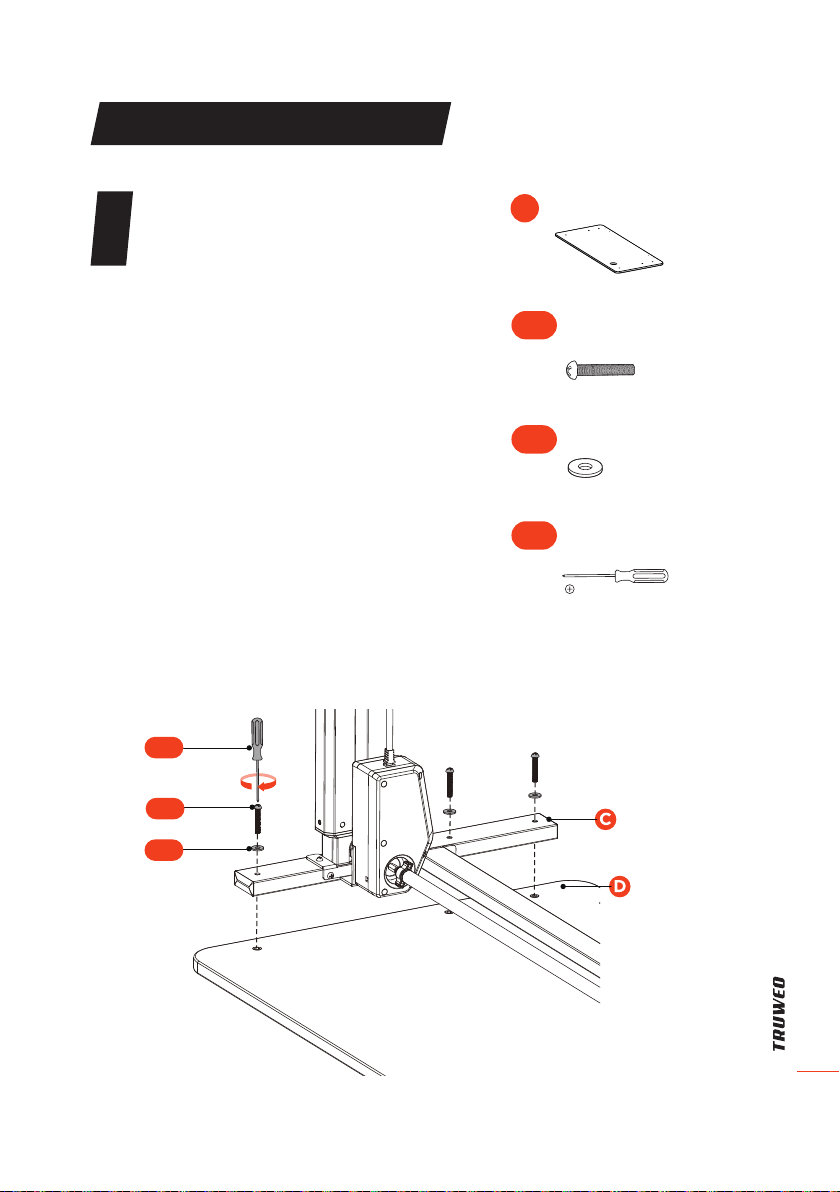
ASSEMBLY INSTRUCTIONS
6Attach the Lifting Columns to the
Desktop
Place a blanket on the oor to prevent
scratches.
• Place the Desktop (D) on the blanket
with the back facing up.
• Attach the assembled Lifting Column
(C) to the Desktop with the Motor
facing inward using 3Screws (S-C)
and 3 Washers (S-F)
• Repeat the same process to
assemble another Lifting Column.
Note:
• Make sure the desktop is facing down
for further installation steps.
• Attach the Lifting Columns with
the Motor on the side of the desk
opposite to the grommet hole.
• DO NOT overtighten the Screws(S-C).
• Insert all 6 Screws and Washers into
the screw holes rst, then tighten
them.
S-F
S-L
S-C
Phillips
Screwdriver
S-L
Phillips Head
Screw × 6
S-C
Washer × 6
S-F
Desktop
D
ELECTRIC STANDING DESK
16
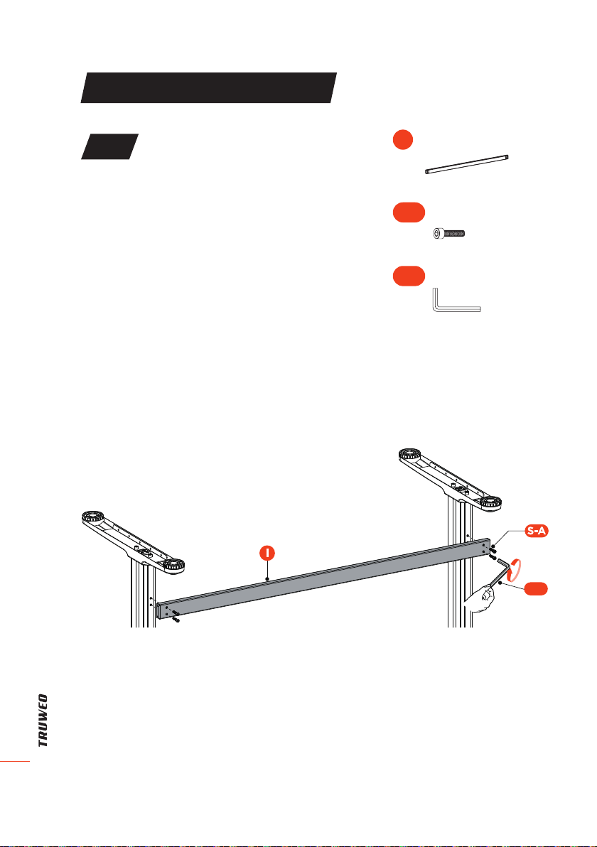
ASSEMBLY INSTRUCTIONS
Assemble the Crossbar (I)
• Attach the Crossbar (I) to the left
and right Lifting Columns. Tighten
the Screws (S-A) using the 5 mm
Allen Wrench (S-J).
Note:
• If the mounting holes on the
Lifting Column cannot align to
the Crossbar, slightly loosen
the Screws(S-C) which have
been screwed into the desktop
during Step 6. Once the Crossbar
is attached, retighten the
Screws(S-C).
• Insert all 4 Screws into the screw
holes rst, then tighten them.
7
S-J
5 mm Allen Wrench
S-J
Crossbar
I
Hex Head Screw × 4
S-A

ELECTRIC STANDING DESK
17
ASSEMBLY INSTRUCTIONS
8
Attach the Controller
• The controller can be assembled
to either the left or right side of the
desktop by the pre-drilled holes.
• Attach the Controller (K) to the
desktop and tighten with 2 Screws
(S-D) using the Phillips Screw driver.
Controller
K
Phillips Head
Screw × 2
S-D
S-L
S-D
Screw Driver
Phillips Screwdriver
S-L

ELECTRIC STANDING DESK
18
ASSEMBLY INSTRUCTIONS
Connect the Cords
• Connect Controller (K) with AC
Adapter (H) and Motor (B) using
the cords as shown in the gure
below.
• Insert Power Cord (J) into the AC
Adapter.
• Once the cords are connected,
attach the Cable Clip (S-G) to the
desktop to organize the cords.
9
S-G
Power Cord
J
Cable Clip
S-G

ELECTRIC STANDING DESK
19
ASSEMBLY INSTRUCTIONS
10 Assemble the Keyboard Tray
1. Attach the left and right
Mounting Clamps (M) and (N) to
the Keyboard Tray (O). Tighten the
Screws (S-N) securely using the
Phillips Screwdriver (S-L).
Note: Check and make sure that
the left and right Mounting Clamps
are not reversed.
2. Turn over the Keyboard Tray and
attach it to the desktop by clipping
the left and right sides. Securely
tighten the knob on the Mounting
Clamps.
O
S-L
S-N
Phillips Screwdriver
S-L
Phillips Head Screw × 4
S-N
Keyboard Tray
O
Left Mounting
Clamp
M
Right Mounting
Clamp
N
Right Side
Left Side
Desktop
Knob

ELECTRIC STANDING DESK
20
ASSEMBLY INSTRUCTIONS
Test the Keyboard Tray
Slide out the Keyboard Tray to check for obstacles within the adjustment
range.
11
This manual suits for next models
2
Table of contents
Other TRUWEO Indoor Furnishing manuals

Popular Indoor Furnishing manuals by other brands

Regency
Regency LWMS3015 Assembly instructions

Furniture of America
Furniture of America CM7751C Assembly instructions

Safavieh Furniture
Safavieh Furniture Estella CNS5731 manual

PLACES OF STYLE
PLACES OF STYLE Ovalfuss Assembly instruction

Trasman
Trasman 1138 Bo1 Assembly manual

Costway
Costway JV10856 manual


