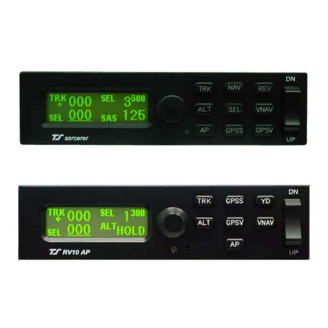
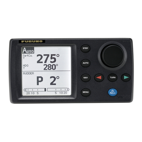
TS DigiTrak Autopilots Operation manual

Installation & User Guide
For
DigiTrak Autopilots
TRUTRAK FLIGHT SYSTEMS
1500 S. Old Missouri Road
Springdale, AR 72764
Ph. 479-751-0250 Fax 479-751-3397
www.trutrakflightsystems.com

INSTALLATION MANUAL
for
DigiTrak Autopilots
TABLE OF CONTENTS
Power Up......................................................................................................................................................................1
Basic Operation ............................................................................................................................................................1
Nav Mode Operation ....................................................................................................................................................1
Mechanical Considerations...........................................................................................................................................2
Magnetic Considerations ..............................................................................................................................................2
RFI / EMI Considerations.............................................................................................................................................3
Electrical Wiring...........................................................................................................................................................3
Connecting GPS Units
Garmin 430/530 .........................................................................................................................................................................4
UPS GX-50/60/65......................................................................................................................................................................4
Garmin-35 Smart Antenna......................................................................................................................................................... 4
Initial Checkout ............................................................................................................................................................5
First Flight ....................................................................................................................................................................6
Magnetic Calibration ....................................................................................................................................................7
DigiTrak Wiring Diagram ............................................................................................................................................8

Power Up
NOTE: When powering up the autopilot ensure that the aircraft is as still as possible for 10
seconds.
The power up of the autopilot takes approximately ten seconds. During the power cycle it is very important that the aircraft be
as still as possible for the initialization of the internal gyro. While the autopilot is in the power up the display will show three
flashing (“–”) characters. If there is a GPS signal present the display will now change to read (“OFF”). If there is not a
valid GPS signal present the display will show three non-flashing (“–”) characters.
Basic Operation
Once the aircraft is off the ground and at a safe altitude, the autopilot can be engaged. There are two ways to engage the
autopilot. Pressing the button will engage the autopilot. If a GPS signal is present, the autopilot will display the current
track and will now hold the track. If there is no GPS signal the display will show “–| – |–” and will be in “heading hold”
mode instead of track hold mode. The second way to engage the autopilot is with the Control-Wheel Switch, pushing and
holding the control wheel switch for approximately 1-1/2 seconds and releasing will engage the autopilot.
Changing the selected track can be done several different ways. One way in which the track can be changed is to momentarily
push and release the or button. This will result in a one-degree change in selected track. If there is no GPS
signal present momentary push and release the or button will result in approximately a one degree change in
heading. The second way to change the selected track is to push and hold the or button. After approximately
1-1/2 seconds the autopilot will enter a constant-rate turn. While turning, if a GPS signal is present, the display of the autopilot
will be a digital DG displaying a gyroscopically smoothened GPS track thoughout the turn. When the desired track is
displayed on the autopilot, push and release the opposite or button. The autopilot will now stop the turn and fly
the new selected track. Note that when the button is pushed to stop the turn, the aircraft is still in a bank; therefore the
autopilot will have to stop the turn and fly back to the selected track. If there is no GPS signal present, and the autopilot is put
into the constant rate turn mode, the display will show a stroboscopically-moving symbol in the direction of the selected turn.
The final way to change the selected track is with the Control-Wheel Switch. Pushing and holding the Control-Wheel Switch
will disengage the servo and the display on the autopilot will be a Digital DG .While holding the Control-Wheel Switch, fly the
aircraft manually to the desired track using the Digital DG display as a reference. Upon release of the Control-Wheel Switch,
the servo will re-engage and the autopilot will now fly the new selected track. If there is no GPS signal present the Digital DG
will not be displayed.
Disengaging the autopilot can be done in two different ways. Pressing the button will disengage the autopilot. The
second way to disengage the autopilot is with the Control-Wheel Switch. Momentarily pushing and releasing the Control-
Wheel Switch will disengage the autopilot.
Nav Mode Operation
When the autopilot is engaged and there is a flight plan present in the GPS, every 3-4 seconds the display will flash (“– F –”).
This is to alert the pilot that the autopilot is receiving a valid GPS flight plan. To enter the Nav Mode, momentarily push the
and buttons at the same time. (Take care not to hold both buttons in for too long a time, or the autopilot will
enter the setup mode instead.) The autopilot display will now begin flashing the Digital DG reading as it maneuvers to
intercept the course line. Once the course-line is intercepted and the autopilot has turned within a few degrees of the desired
track, the display will change from the flashing DG to (“– 0 –”) indicating that the autopilot is now tracking the course line.
Pushing any button on the autopilot will exit the Nav Mode. When on course, 1 or 2-degree excursions are normal. When the
end of the flight plan is reached or the flight plan is cancelled on the GPS unit, the autopilot will continue flying the track it
was flying when the flight plan ended. If the flight plan has multiple waypoints, the autopilot will make the necessary turn at
each waypoint. Because, typically, the information from the GPS to the autopilot does not change until the waypoint is crossed,
the autopilot will over-fly the waypoint, and then will fly back to intercept the new course line. Some GPS units have a “turn
anticipation” feature, and if this feature is enabled on the GPS the autopilot may turn prior to reaching a given waypoint.
TruTrak Flight System Digitrak Installation & User Guide
1 October 2002 Printing

Mechanical Considerations
The installation information in this section is extremely important and must be clearly
understood by the installer. Improper servo installation or failure to observe and diagnose
installation problems prior to flight can result in extremely serious consequences, including
loss of ability to control the aircraft. If there are any questions on the part of the installer it
is mandatory to resolve these questions prior to flight of the aircraft.
Most modern experimental aircraft use push-pull tubes to drive the primary controls. These tubes generally have a total travel
of 3” or less; therefore, it is best to connect the autopilot servo to the primary control by the same method. This connection
consists of an arm on the servo connected by a push-pull rod to the primary control. Rod-end bearings are required on each
end of the push-pull rod.
The servo arm must not rotate even near to the point called OVER CENTER, the point at which the primary
aircraft control would lock up.
This is a condition that would result from the servo being back driven when the pilot operates the controls, or
from the servo itself driving the controls to a stop. To protect against this mechanical stops are supplied with the
servos. These stops are drilled so that they can be mounted at different angles as required (18°intervals).
In addition to the proper use of the stop it is important to know the amount of travel on the primary control that
the servo can handle. With the push rod connected to the outermost hole (1 ½”) the travel on the primary cannot
exceed 2 ½”, the intermediate hole 2 1/16”, and the inner hole 1 5/8”.
It is important to note that the servo travel should be very nearly the same in both directions. In most cases this
means that the servo arm needs to be perpendicular to the push rod but there are exceptions such as the RV-4 and
RV-8 installations.
There will be installations in which space does not permit the use of the stop. When this is done the aircraft’s primary control
stops must be positive and care must be taken to be sure that the servo drives the push rod the same distance in both directions,
and that the travel limits of the servo arm are not exceeded.
There are installations in which the travel of the push-pull tube exceeds the allowable 2 ½”. For such installations, the drive
can be applied to a bell crank at a radius point that moves the desired 2 ½” of maximum allowed travel in the outermost hole of
the arm.
When there is no way to have a drive point of less than 2 ½” or when the primary control is cable-driven it is necessary to use
the capstan-cable servo drive. When this is done the servo should be mounted so that the 1/16” diameter cable which wraps
around the capstan when extended parallel to the primary cable is approximately 3/16” from the primary cable. If the primary
control travel does not exceed 5” the cable-locking pin will be 180°away from the point at which the cable leaves the capstan.
When the primary control is at the neutral point this means the total cable wrap around the capstan is 360°. If the primary
control travel is greater than 5” the cable wrap is 720°and the pin is adjacent to the output point when the primary control is at
the neutral point.
The cable clamps when properly installed will not slip and thus get loose, but it is desirable to nicopress or swedge a fitting on
to the cable so as to provide added assurance that the cable will not become slack. If the bridle cable is not sufficiently tight
there will be lost motion in the autopilot drive. This will result in hunting (oscillation).
Magnetic Considerations
Because the autopilot contains a built-in magnetometer for a backup source of heading in the event of GPS loss, it is important
to try to locate the programmer away from known sources of magnetic disturbance. The calibration procedure can account for a
moderate amount of fixed disturbance (for example, nearby iron objects) but it cannot adjust for changing magnetic fields such
as would be generated by aircraft compasses or certain electrical devices. One such source of such problems is the “Flag”
mechanism in some older DG or HSI devices. These units use a solenoid to hold the flag out of sight, and the magnetic field
will then change when the flags come and go. If at all possible, place the autopilot so as to be as far as possible from such
devices. A hand-held compass can be used to assist in finding fixed or variable disturbances prior to installation of the
autopilot. Even a few inches can make an appreciable difference in the magnetic disturbance level. It should be noted also that
strobe light controls generate very strong currents in their wiring, thus they will create a periodically pulsating magnetic field
TruTrak Flight System Digitrak Installation & User Guide
2 October 2002 Printing

disturbance. Shielding has no effect on this problem; the only solution is to keep strobe light wiring as far away as possible
from any electronics which can be affected by pulsating magnetic fields.
RFI/EMI considerations
The autopilot programmer is shielded and does not generate any appreciable level of electromagnetic interference. Moreover,
the servo lines (except for power and ground) are low-current and cannot contribute to RF interference. The servo power and
ground lines do have switching currents through them, but so long as there are no parallel runs of servo power and ground lines
with such things as poorly-shielded antenna lines or strobe light power lines, there is no need to shield the servo harnesses.
The autopilot itself has been internally protected from RF interference and has been tested under fairly extreme conditions,
such as close proximity to transmitting antennas. However, it is always good practice to insure that such antennas are properly
shielded and not routed directly over or under sensitive panel-mounted electronic equipment. Most problems in this area are the
result of improper RF shielding on transmitting antennas, microphone cables, and the like. The most sensitive input to the
autopilot is the Control Wheel Switch input. This line should not be routed in parallel with transmitting antennas or other
sources of known RF interference. If necessary, it can be shielded with the shield connection to pin 8 of the autopilot
connector.
Electrical Wiring
The table below provides a brief explanation of each pin function on the main 15-pin connector P101.
1
9 101112131415
2345678
Rear 15-Pin Connector P101
viewed from rear of unit
P101
Pin Function Notes
1 Autopilot Master (+12 to +14 V DC). The autopilot itself draws less than 0.3 ampere. Most of
the current required by the system is used by the servo (up to 1Amp depending on torque
setting) and a smaller amount (up to 180 mA) for the illuminated pushbuttons.
2 Control Wheel Switch. Connect as shown in wiring diagram to a SPST momentary switch
located remotely to the autopilot for convenient engage/disengage function.
3 Primary Serial Input. Baud rate selectable 1200,2400,4800 or 9600 baud. Automatically
decodes NMEA-0183, Garmin Aviation Format, or Apollo/UPSAT Moving-Map format.
Provides directional reference to the autopilot.
4,5,6 Reserved. Do not connect to these pins.
7 Roll Servo Torque Control. A signal from the autopilot to the roll (aileron) servo which sets
the amount of torque to be delivered by the servo.
8 Ground Connection. Provide #20 AWG to common grounding point.
9 Power Connection to Servo. Provide #20 AWG to Servo Pin 1.
10 Instrument Lamp Dimmer. A source of variable DC from external dimming source. Drives
the LED brightness control and three 60 mA lamps. If left disconnected, LED will be full-on
but buttons will be unilluminated.
Roll (aileron) Servo control lines. These lines cause the stepping motor in the roll servo to run
in the appropriate direction at the desired velocity. They are small-signal lines and do not have
any substantial current-carrying capability or require any special shielding. Connect to roll
servo as shown on wiring diagram.
Wiring to roll servo J201
J101 Pin 11 Pin 12
Direction of servo arm / capstan rotation
(as viewed from face of the servo body)
for RIGHT aileron
Standard J201-4 J201-5 Servo CCW (counter-clockwise) ÎRIGHT
11
12
13
14
Reversed J201-5 J201-4 Servo CW (clockwise) ÎRIGHT
Reverse servo direction if
necessary by swapping
wires on pin 11 and 12.
See note 3 on wiring
diagram.
15 Ground Connection to Servo. Provide #20 AWG to Servo Pin 9.
TruTrak Flight System Digitrak Installation & User Guide
3 October 2002 Printing

Specific connections for certain commonly-used in-panel GPS units
Note that the information in the tables is based upon the best information available from each manufacturer’s documentation at
the time of publication. Please consult the appropriate installation manual for confirmation of wiring information.
Garmin 430 and 530 connections to DigiTrak autopilot
P4001 [P5001] on
Garmin 430 [530] Signal Name
(Garmin) Signal Name
(DigiTrak) P101 on
DigiTrak Autopilot
56 GPS RS 232 OUT 1 Primary Serial Input 3
Garmin 430/530 setup instructions:
Power 430/530 up and turn it on while holding down the ENT key. Release the ENT key when the display activates. After the
data base pages, the first page displayed is the MAIN ARINC 429 CONFIG page. While in Configuration mode, pages can be
selected by ensuring the cursor is off and rotating the small right knob. To change data on the displayed Configuration Page,
press the small right knob (CRSR) to turn on the cursor. Turn the large right knob to change between data fields. Turn the large
or small right knob to change a field that the cursor is on. Once you have made the desired selection, press the ENT key to
accept the entry.
Ensure that the cursor is off and use the small right knob to advance to the MAIN RS232 CONFIG page.
On the row labeled CHNL1, select OUTPUT ÎAviation.
Note that for the Garmin units, the autopilot will need to be set for 9600 baud.
UPSAT GX-50/60/65 connections to DigiTrak autopilot
37-Pin Connector
on UPSAT
GX-50/60/65
Signal Name
(UPSAT) Signal Name
(DigiTrak) P101 on
DigiTrak Autopilot
5
or
22
Use pin 5 – TxD1
or
pin 22 – TxD2
Primary Serial
Input
3
GX-50/60/65 setup instructions:
Power the GX-50/60/65 up and turn it on while holding down the leftmost and rightmost “smart keys.”
Rotate the LARGE knob to the Serial Interface Configuration “CH RX TX” page. Press SEL (the selection fields will start
flashing), rotate the LARGE knob to select the port, rotate the SMALL knob to select the desired configurations, then press
ENT when complete.
Depending upon other equipment to be driven by the GX unit, either channel 1 or channel 2 may be chosen. If another piece of
equipment is to be driven by the GX unit, and that equipment uses the MOVING MAP format, then the DigiTrak can be driven
from the same pin as the other external equipment. (The GX unit will not allow for both of its output channels to be set to the
same output format). If there is no other equipment other than the DigiTrak to be driven by the GX unit, simply use channel 1
(pin 5) on the GX unit.
Select “MOVING MAP” For CH 1, Tx column and wire pin 3 on the DigiFlight to pin 5 of the GX unit,
OR
Select “MOVING MAP” For CH 2, Tx column and wire pin 3 on the DigiFlight to pin 22 of the GX unit.
To restore the GX-50/60/65 to normal operation, switch its power off, then back on.
Note that for the GX-50/60/65 units, the autopilot will need to be set for 9600 baud.
TruTrak Flight System Digitrak Installation & User Guide
4 October 2002 Printing

Garmin-35 “Smart Antenna” connections to DigiTrak autopilot
Garmin-35
Wire Color Signal Name
(Garmin) Signal Name
(DigiTrak) P101 on
DigiTrak Autopilot
Red PWR Primary Power 1
Black GROUND Ground 8
White GPS RS 232 OUT 1 Primary Serial Input 3
There is no necessary setup procedure for the Garmin-35 unit. It may require up to 45 minutes to achieve a position fix the first
time it is powered on; afterwards it will take less time to obtain a position fix as it contains its own battery and position
memory. To use this unit, configure the DigiTrak’s baud rate to 4800 baud in the setup screen. This unit does not provide
course guidance or flight planning. Its sole function is to provide the autopilot with a source of ground track and ground speed
information to slave the autopilot’s internal DG function.
DigiTrak Initial Checkout
Once wiring is completed the autopilot should be tested in the aircraft while on the ground. The first step is to enter the setup
mode on the autopilot and set all parameters to their correct values. Apply power to the autopilot programmer.
When power is first applied to the unit, the display will show three flashing dash (“–” ) characters. After approximately ten
seconds, the autopilot is ready to be set up for operation, indicating three non-flashing dashes on the display. (If a GPS unit
happens to be connected to the autopilot, has a valid position fix, and is running at the correct baud rate, the autopilot will
indicate the word “OFF” instead of the three dashes.)
Engage the autopilot by pressing . Then press and hold and at the same time, until the first setup screen is
displayed.
This display will show a flashing “1” and a two-digit number from 1 to 12, representing the autopilot activity level. With the
activity setup screen on the display, use or as necessary to adjust the lateral activity value to a value of 1 or 2.
Press to enter the activity value and advance to the next screen.
The second setup screen, with a flashing “2” is used to set the torque of the autopilot servo. Use or to adjust the
torque value close to the maximum value of 12. Once that is done, press to enter that value and advance to the next
screen.
The third setup screen, with a flashing “3” is used to set the baud rate (speed) of the serial interface to the GPS receiver. Use
or to select among five choices as shown in the table below
Displayed value RS-232 serial rate
06 600 Baud
12 1200 Baud
24 2400 Baud
48 4800 Baud
96 9600 Baud
Having chosen the desired baud rate, press to enter that value and advance to the next screen.
The fourth setup screen, with a flashing “4” provides the option for calibrating the internal backup magnetometer. To this
question, leave the answer set to 0 (which means “no”) at this time. This operation will be done at a later time during flight
testing.
Press to leave the setup mode. The DigiTrak display will now show “–| – |–” indicating the magnetic “heading-hold”
mode. ( If GPS were indicating sufficient ground-speed for flight, the display would be showing a 3-digit selected ground track
instead.)
Press . The DigiTrak display will now return to its disengaged (off) state, which is three “–” characters if no GPS fix has
been obtained, or “OFF” if a GPS position fix has been obtained.
TruTrak Flight System Digitrak Installation & User Guide
5 October 2002 Printing

While the autopilot is in its disengaged (off) mode, press and hold and simultaneously. The display will now
show “–| – |–” with the center dash character blinking, indicating the Manual Gyro Set operation. Continue to hold both
buttons in for a few seconds while the autopilot is not being moved about, to re-center the gyro manually
The next step in the check-out procedure is to verify that the servo runs, and in the correct direction. Press to again
engage the autopilot. The servo should be responding at this time, moving the controls only very slowly in attempt to hold
magnetic heading constant. Press and hold for about 1-1/2 seconds. The autopilot will now move the controls in an
attempt to cause a constant-rate turn towards the right. If servo direction is not correct, the wires going to pins 4 and 5 of the
roll servo (pins 11 and 12 on the main connector) must be reversed to achieve the correct response. If the servo does not move
at all, double-check the torque setting (setup screen 2) to make sure it is at least 10. If a servo jitters but does not actually
rotate, check the wiring on the four servo drive lines to that servo for continuity and correctness. If the servo does not seem to
have any torque, check the roll torque control line for continuity and correctness. With a torque setting of 12, and the autopilot
engaged, the torque control line should measure approximately 4.9 volts DC.
Press and release to stop the continuous turn. Then press and hold for about 1-1/2 seconds. The autopilot will
now move the controls in attempt to cause a constant-rate turn to the left. Notice the stroboscopically-moving display
indicating the autopilot is in its constant-turn mode.
Press and release to stop the continuous turn.
While the servo is running, check that the servo arm or capstan is properly operating the controls. For servo installations using
an arm, check that as the controls go from limit to limit the arm of the servo remains in the operating range of the servo (a
maximum of 100 degrees total rotation) and that when the controls are centered, the connecting push rod is approximately
perpendicular to the arm of the servo. For capstan systems, insure that the cabling remains at proper tension and is properly
secured as the servo moves the controls from stop to stop. Insure that the servo remains secure in its mounting and does not
flex its mounting bracket as it drives the control to its stops. For installations using an arm, insure that as the servo moves the
control towards the end of control travel it does not cause the main control’s torque tube to flex in any way that could cause
control system lockup at the extremes of servo travel. Insure that any “lost motion” in the linkages is eliminated or minimized,
in order to maximize the performance of the autopilot. Lost motion (dead zone) will result in wandering or slow “hunting”
behavior in flight. Lost motion in the linkage can best be observed by temporarily clamping the servo arm and gently moving
an aileron back and forth, while observing how much aileron movement takes place against the clamped servo.
The next step in the check-out procedure is to verify that the serial input from the GPS receiver is being properly received and
interpreted. With the aircraft outside of any building, power up the GPS receiver and the autopilot. After the GPS receiver
acquires its position, the autopilot display will change from “ – – – ” to “OFF” indicating that valid position data is available.
.If the word “OFF” is not displayed, even after it is known that the GPS unit has a position fix, the problem must be diagnosed.
Possible reasons for such a problem are,
Pin 3 on the connector is not wired to a source of RS-232 serial data
The GPS receiver’s baud rate disagrees with that selected within the autopilot
The GPS receiver’s serial output port has not been properly configured to provide the information
The remaining adjustments relate to the dynamics of flight and compensation of the magnetic backup system in the autopilot.
DigiTrak First Flight
The first flight should be done after having completed all the setup and testing on the ground. For the first flight, it is important
that the GPS unit is properly functioning with the autopilot, so that the dynamics of flight can be set without consideration of
the calibration of the magnetic backup system. As discussed earlier, when there is proper connection to the serial input of the
autopilot, the display will show “OFF” when it is disengaged and valid GPS data is present. If this does not occur, it is best to
diagnose and fix the problem prior to first flight of the autopilot.
The activity adjustment (setup screen 1) determines how briskly the autopilot responds to roll disturbances. The setting can be
adjusted, in flight, over a wide range; thus the autopilot can be tailored to adapt to any aircraft installation.
The activity adjustment covers a numeric range of 0 to 12. Unless the value for a particular aircraft is provided by TruTrak, it is
advisable to start with a setting of zero and work up from there. Most installations would ultimately require somewhat higher
settings.
On the first flight, manually fly the aircraft to a suitable area for testing. Engage the autopilot by pressing . Observe that
the display now shows the captured GPS ground track as the selected direction of flight.
TruTrak Flight System Digitrak Installation & User Guide
6 October 2002 Printing

Press and hold the and buttons simultaneously until the first setup screen is shown on the display. The digit “1”
will be flashing, followed by the activity value that was set earlier during pre-flight setup. Use to select the value zero
(0), and observe the resulting control movement. Using , increase the value one setting at a time, taking time to observe
an increasing level of control response. At some point, if too high a setting is chosen, the autopilot will be jittery and over-
active. Back the setting down using until the autopilot is responsive but not over-active. It is best if these adjustments
are made in conditions of light to moderate turbulence (the TruTrak loves turbulence) so as to make it easy to observe the
response of the autopilot to disturbances. It will be noted that a fairly limited range of activity setting will be acceptable; too
low a value will result in sluggish response, while too high a value will result in nervous, inappropriate response. Within this
acceptable range there is room for individual preference; some people prefer a more aggressive autopilot than others. It should
be noted that any builder can accomplish this adjustment procedure and no professional is required.
Once the desired activity level is established, press to store the value and move to the second setup screen.
In the second setup screen, the digit “2” will be flashing, followed by the torque value that was set earlier during pre-flight
setup. Again, it is best that this be done in light to moderate turbulence. The reason is that more torque is required of the
autopilot in turbulence than is the case in still air, because the velocity of the servo is greater as turbulence requires more rapid
servo movement. This means that the higher the activity setting, the higher the required torque setting.
The reason for setting the torque to a setting less than its maximum (12) is to reduce the current draw of the servo and to make
it easier to override the autopilot should the need arise. Manual override is not normally required, as using the control-wheel
switch or will disengage the autopilot, but it is best to have a setting of torque which can be comfortably overridden if
necessary. Starting with the maximum torque setting (12), gradually decrease the value using , until it is observed that
the autopilot no longer has the necessary torque to respond to disturbances; then increase the setting somewhat from that level
using until no more slippage of the servo is observed. The clearest evidence of servo slippage is that the autopilot is no
longer able to roll the aircraft back to a level attitude after a roll disturbance occurs.
Once the desired torque level is established, press to store the value. Press two more times to skip over setup
screens 3 and 4 and return to the primary flight display in which the selected GPS ground track appears on the display.
The setup procedure can be repeated whenever it is desired to modify the dynamic flight charactistics of the autopilot.
Magnetic Calibration
The DigiTrak autopilot contains a built-in magnetometer which is used to maintain gyro centering and slaving for the built-in
Electronic DG of the autopilot in case of GPS loss. This magnetometer is calibrated at the factory in a disturbance-free
environment, but once installed in the aircraft it may be necessary to account for any fixed magnetic disturbances in the aircraft
itself.
For best results, this operation should be done on a day when the winds are relatively calm, so that air is still and heading and
ground track are approximately the same in all directions. The operation should be deferred until such flight conditions exist.
For this operation the autopilot will fly four legs of approximately half a minute each, first north, then east, then south, then
west. Prior to the calibration sequence, fly the aircraft to an area where this can suitably be done. Verify that the autopilot is
receiving GPS properly (note that “OFF” appears in the display when the autopilot is off, and the selected ground track appears
when the autopilot is on). Choose and hold an appropriate altitude and engage the autopilot using or the control stick
switch. During the calibration sequence, it is important that aircraft pitch attitude remain as constant as possible.
Once the autopilot is engaged, press and simultaneously until the first setup screen appears. Press three
times, to cycle through the activity, torque and baud rate setup screens until the fourth setup screen shows on the display. This
will be a flashing digit “4” followed by the digit “0”. Press to select 1 (for “yes”) and then press . The autopilot
screen will announce the beginning of the calibration sequence with the digits “000” flashing as it turns the aircraft towards
North. It will fly the aircraft to a ground track of 000 degrees, and once established on course the digits will cease flashing as
the autopilot gathers and averages magnetometer readings for this direction. This process requires approximately ten to twenty
seconds of steady flight on a ground track of 000 degrees. Having gathered the required data, the autopilot will announce its
turn towards East with a flashing “090” display. Again, the autopilot rolls out and gathers data. This process is continued
through South, and finally West. Having completed this operation, the display will change to “– C –” indicating that
calibration has been successful. (A display of “– F –” at any time during the magnetic calibration sequence means that the GPS
signal has been lost and the calibration cannot be completed. Repeat the calibration once reliable GPS reception is again
present.) Confirm the calibration sequence by pressing . At this point, the autopilot will revert back to its normal flight
mode with a direction selector, but it now has a magnetic backup mode sufficient to fly the aircraft drift-free in the event of
GPS loss.
This concludes the in-flight setup of the DigiTrak autopilot.
TruTrak Flight System Digitrak Installation & User Guide
7 October 2002 Printing

(View Facing Rear of unit)
DIGITRAK EXTERNAL WIRING DIAGRAM
ROLL SERVO
J201 9-PIN FEMALE
D-SUBMINIATURE
12345678
9101112131415
PROGRAMMER MODULE
J101 15-PIN FEMALE
D-SUBMINIATURE
FROM GPS RECEIVER
PRIMARY SERIAL INPUT
CONTROL WHEEL SWITCH
AIRCRAFT
ELECTRICAL
GROUND ( - )
INSTRUMENT LAMP
DIMMER (See Note 2)
INSTALLATI
O
NN
O
TES:
USE #20 AWG FOR POWER AND GROUND WIRES AS SHOWN BELOW IN
HEAVY LINES (PINS 1,9, 8 AND 15 ON CONTROL UNIT J101,
AND PINS 1 AND 9 ON 9-PIN CONNECTOR J201).
ALL OTHER WIRING #20 TO #24 AWG.
INSTRUMENT LAMP DIMMER CONTROL IS OPTIONAL.
CONNECT J101 PIN 10 TO DIMMER CONTROL OR LEAVE UNCONNECTED.
REVERSAL OF SERVO DIRECTION CAN BE
ACCOMPLISHED IF NECESSARY BY SWAPPING
WIRES AT PINS 4 AND 5 OF THE SERVO
CONNECTOR (J201).
1
6
2
7
3
8
4
9
5
1.
2.
3.
NOTE
3
TruTrak Flight System Digitrak Installation & User Guide
8 October 2002 Printing

TRUTRAK FLIGHT SYSTEMS
1500 S. Old Missouri Road
Springdale, AR 72764
Ph: 479-751-0250 Fax: 479-751-3397
www.trutrakflightsystems.com
Table of contents
Other TS Autopilot System manuals
