TruTrak Vizion PMA C180 User manual

Rev: B Vizion Install Appendix E C180, C182-
C182D, C185
TruTrak Doc: 255
1
Appendix E
Vizion PMA Autopilot C180, C182-C182D, C185
Installation
NOTE:
The installation of the Vizion autopilot is NOT compatible with the
Robertson STOL system. If the subject aircraft has a Robertson STOL
system installed, please contact TruTrak Flight Systems and do not
proceed with the installation of the Vizion autopilot.
RESTRICTION ON USE, DUPLICATION, OR DISCLOSURE OF
PROPRIETARY INFORMATION
THIS DOCUMENT CONTAINS PROPRIETARY INFORMATION OF
TRUTRAK FLIGHT SYSTEMS, INC. AND MAY NOT BE REPRODUCED, COPIED,
DISCLOSED OR UTILIZED IN ANY WAY, IN WHOLE OR IN PART, WITHOUT THE
PRIOR WRITTEN CONSENT OF TRUTRAK FLIGHT SYSTEMS, INC.
Prepared by
TruTrak Flight Systems, Inc.
Function/Title
Name
Prepared by
Engineering
Zach Williamson
Prepared by
President
Andrew Barker
Checked by
GM
Moss Foster
Approved by
President
Andrew Barker
Make%
TCDS%
Models%
Textron%Aviation,%Inc.%
5A6%
180,%180A,%180B,%180C,%180D,%180E,%180F,%180G,%
180H,%180J,%180K%
Textron%Aviation,%Inc.%
3A13%
182,%182A,%182B,%182C,%182D%
Textron%Aviation,%Inc.%
3A24%
185,%185A,%185B,%185C,%185D,%185E,%A185E,%A185F%

Rev: B Vizion Install Appendix E C180, C182-
C182D, C185
TruTrak Doc: 255
2
Table of Contents
1.%Document Revision History ................................................................................... 3%
2.%Cessna C180, C182-C182D, C185 Controller / Wiring Harness Installation .............. 4%
2.1.%Wiring%Harness%Materials%List%..............................................................................................................%4%
2.2.%Wiring%Harness%/%Controller%Mounting%Instructions%..................................................................%5%
3.%Cessna C180, C182-C182D, C185 Servo Installation ............................................. 11%
3.1.%Roll%Servo%Materials%List%......................................................................................................................%11%
3.2.%Cessna%C180,%C182-C182D,%C185%Roll%Servo%Mounting%Instructions%...............................%12%
3.3.%Pitch%Servo%Materials%List%....................................................................................................................%19%
3.4.%Cessna%C180,%C182-C182D,%C185%Pitch%Servo%Mounting%Instructions%.............................%20%
3.5.%Cessna%C180,%C182-C182D,%C185%Vizion%Roll%IPC%.....................................................................%27%
3.6.%Cessna%C180,%C182-C182D,%C185%Vizion%Pitch%IPC%...................................................................%28%
4.%Cessna C180, C182-C182D, C185 Autopilot Settings ............................................. 29%
4.1.%Lateral%Autopilot%Settings%....................................................................................................................%29%
4.2.%Vertical%Autopilot%Settings%..................................................................................................................%30%

Rev: B Vizion Install Appendix E C180, C182-
C182D, C185
TruTrak Doc: 255
3
1. Document Revision History
Rev%
Description%
Pages%
Date%
IR%
Initial%Release%
31%
8-16-18%
A%
Added%BK%part%numbers,%made%changes%for%PV.40%
software%
32%
5-15-19%
B%
Added%note%on%front%page%regarding%Robertson%
STOL%incompatibility.%
32%
8-9-19%

Rev: B Vizion Install Appendix E C180, C182-
C182D, C185
TruTrak Doc: 255
4
2. Cessna C180, C182-C182D, C185 Controller / Wiring Harness
Installation
2.1. Wiring Harness Materials List
Qty%
Description%
Part%Number%
1%
Vizion%Wiring%Harness%30’%
8220-033%
1%
Vizion%2”%Controller%
OR%
Vizion%3”%Controller%
OR%
Vizion%Flat%Pack%Controller%
8000-174%or%8000-183%
OR%
8000-176%or%8000-184%
OR%
8000-175%or%8000-185%
100%
MS3367-1-0%Cable%Tie%
%
2%
Connector%D-sub%Female%9%Pin%Crimp%
2100-044%
16%
Female%Socket%Crimp%Connector%D-sub%
2100-045%
2%
Connector%Backshell%9%Pin%
2100-010%
1%
Vizion%Emergency%Level%Button%Kit%
8100-113%
1%
Vizion%Limitations%Placard%
8300-092%
1%
5A%AP%circuit%breaker%(not%supplied)%
%
1%
Control%Wheel%Steering%Switch%%
(not%supplied,%but%MUST%be%RED%in%color)%
%
1%
AP%Master%Switch%(not%supplied)%
%
4%
6-32%X%3/8”%Instrument%mounting%screw%%
(not%supplied)%
%
N/A%
Various%terminals%and%pins%for%connection%of%
power%and%GPS%% %
%
N/A%
1/8”-27%NPT%male%fittings%and%tees%for%
connecting%the%A/P%pitot%and%static%to%the%
aircraft%systems%
%

Rev: B Vizion Install Appendix E C180, C182-
C182D, C185
TruTrak Doc: 255
5
2.2. Wiring Harness / Controller Mounting Instructions
1. Begin%by%disconnecting%the%aircraft%battery.%
%
2. Select%a%mounting%location%for%the%autopilot%controller.%%%
2.1. Consider%the%overall%mounting%depth%of%the%controller%with%pitot,%static,%and%
electrical% connections% and% allow% clearance% where% necessary,% especially%
surrounding%the%moving%yoke%assembly.%%%
2.2. Ensure%that%mounting%location%does%not%require%autopilot%servo%lines%to%run%
near%com%antenna%coax.%
2.3. Ensure%that%there%is%sufficient%space%near%the%autopilot%controller%to%install%the%
Vizion%Limitations%Placard%(Trutrak%P/N%8300-092)%
%
3. Remove%the%instrument%panel%and%panel%overlays%as%necessary.%
4. Remove%the%seats.%
5. Remove%the%left%A-pillar%and%kick%panel%trim.%
6. Remove%carpeting.%
7. Wiring%harness%routing.%
7.1. Route%the%pitch%(white)%and%roll%(black)%servo%harnesses%from%the%controller%
to%the%left%side%of%the%panel.%
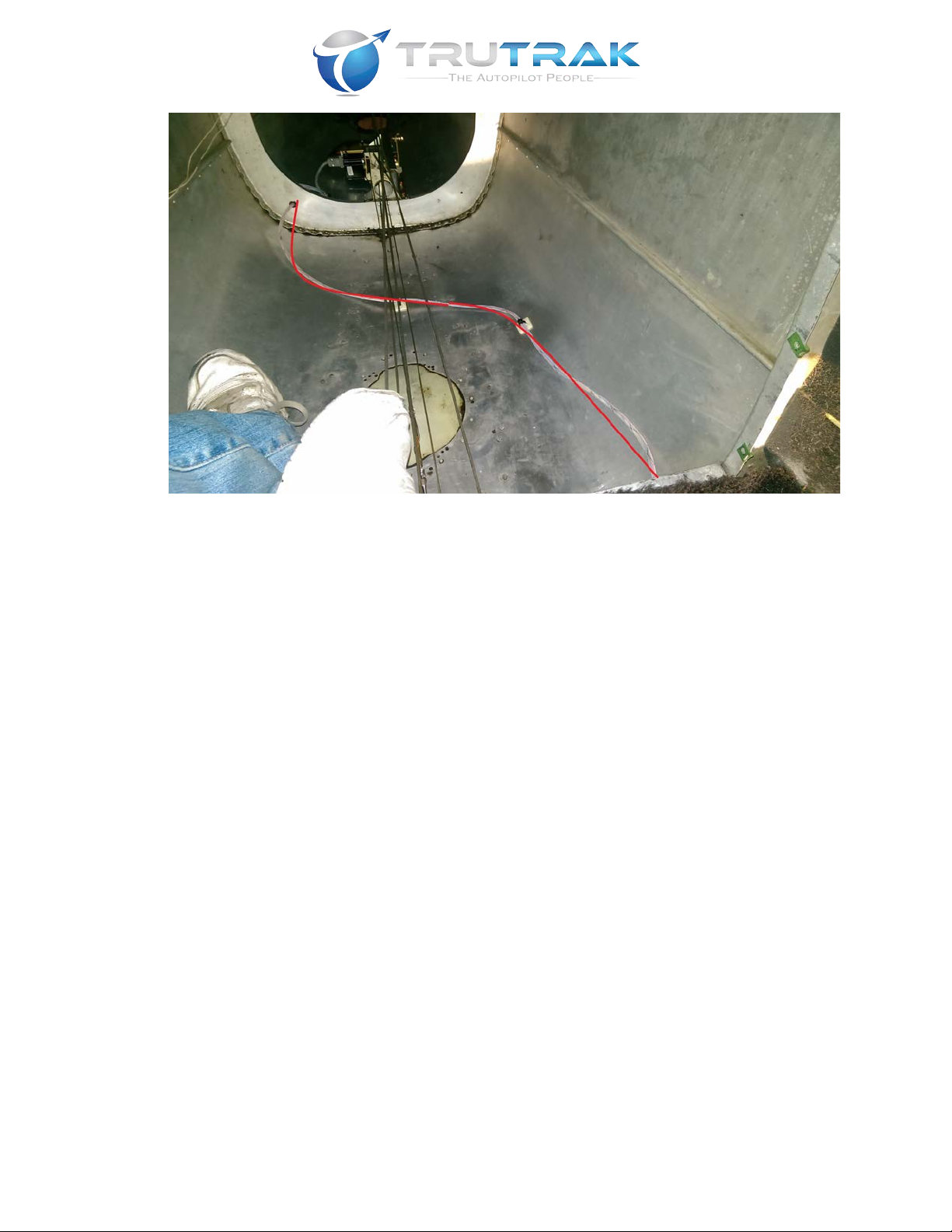
7.2. Route%the%roll%(black)%servo%harness%up%the%left%A%pillar%and%out%the%leading%
edge%of%the%left%wing%as%shown%in%Figure%2-1,%Figure%2-2,%and%Figure%2-3.%%
Extend%the%excess%harness%out%the%inspection%hole%just%forward%of%the%
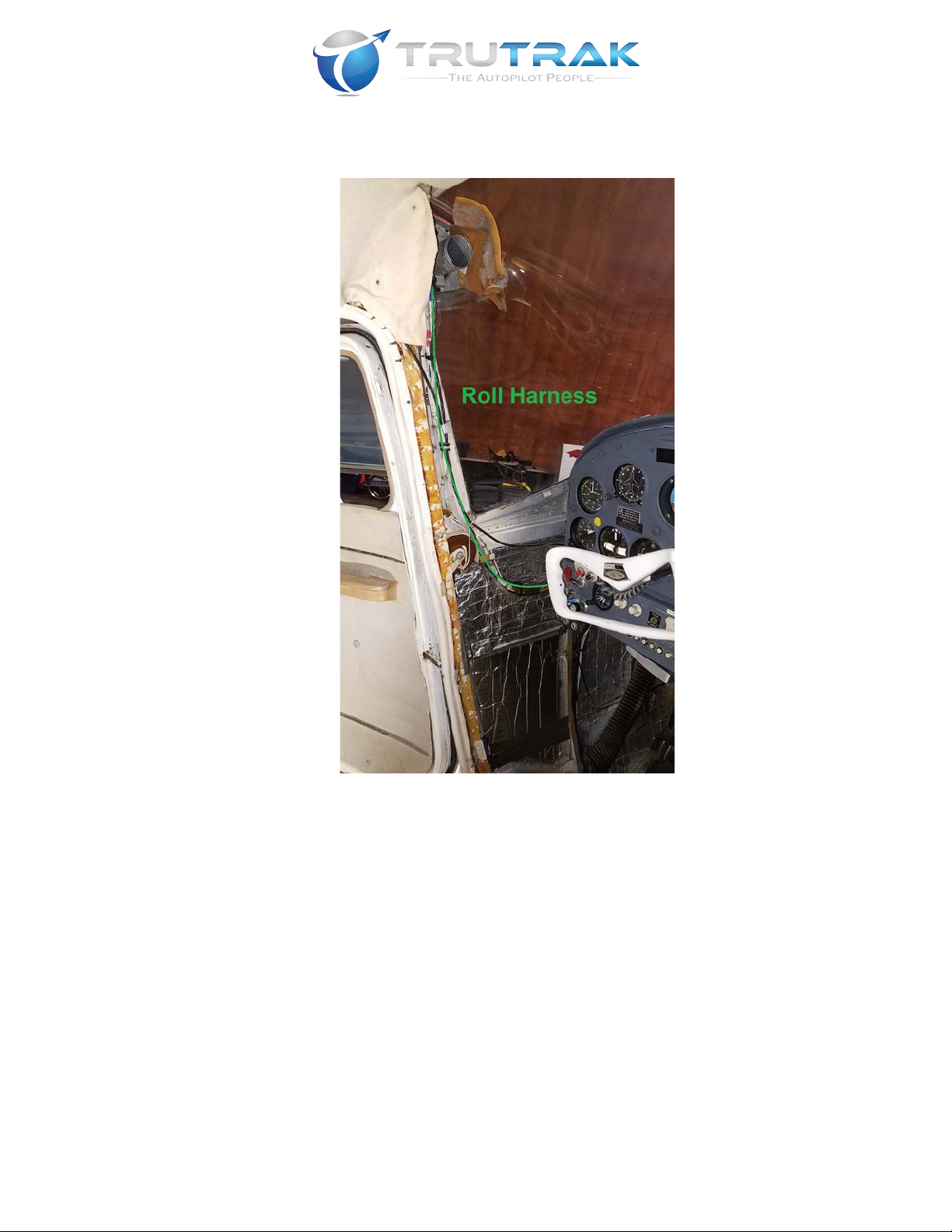
Rev: B Vizion Install Appendix E C180, C182-
C182D, C185
TruTrak Doc: 255
6
inboard%end%of%the%left%aileron.%%The%excess%length%will%be%trimmed%and%the%
harness%terminated%when%the%roll%servo%is%installed.
Figure 2-1!

Rev: B Vizion Install Appendix E C180, C182-
C182D, C185
TruTrak Doc: 255
7
Figure 2-2
Figure 2-3!
7.3. Route%the%pitch%(white)%servo%harness%down%the%left%kick%panel%and%under%the%
floor.%Continue%running%the%harness%to%the%pitch%servo%mounting%location%as%
shown% in% Figure% 2-4% and%Figure%2-5.%Use% self-adhesive% cable% tie% anchors% to%

Rev: B Vizion Install Appendix E C180, C182-
C182D, C185
TruTrak Doc: 255
8
secure%the%harness%where%needed.%%The%excess%harness%length%will%be%trimmed%
and%the%harness%terminated%when%the%pitch%servo%is%in%place.%
Figure 2-4!
Rev: B Vizion Install Appendix E C180, C182-
C182D, C185
TruTrak Doc: 255
9
Figure 2-5!
8. Select% appropriate% mounting% locations% for% the% AP% Master,% AP% Circuit% Breaker,%
Emergency%Level%and%control%wheel%steering%switches.%%Connect%these%items%per%
the% Vizion% wiring% diagram% in% the% Vizion% PMA% Installation% Guide% (TruTrak% Doc.%
166).%!%
!
8.1. "##!$%&'(!$)!%*$(!(%&+!,-&!-&./$-&0!%1!2&!$)(%,##&03!!4*&!"5!6,(%&-!78$%9*:!
"5! ;$-9/$%! <-&,=&-:! ,)0! ;1)%-1#! >*&&#! 7%&&-$)?! (8$%9*&(! '/(%! 2&!
#,2&#&03!!4*&!;1)%-1#!>*&&#!7%&&-$)?!78$%9*!'/(%!2&!@AB3%
%
9. Connect% GPS% inputs% per% the% Vizion% wiring% diagram% in% Vizion% PMA% Installation%
Guide%(TruTrak%Doc.%166)%
%
CD3 ;1)0/9%! +$%1%! E! (%,%$9! 9*&9=! 1F! ,$-9-,F%! (G(%&'! 2&F1-&! 1+&)$)?! ,)G! +$%1%E!
(%,%$9!91))&9%$1)(H!
%
11. Mount%autopilot%controller%in%panel%using%4%6-32%X%3/8”%screws.%%Connect%wiring%
harness%and%connect%pitot%and%static%per%Vizion%PMA%Installation%Guide%(TruTrak%
Doc.%166).%
%
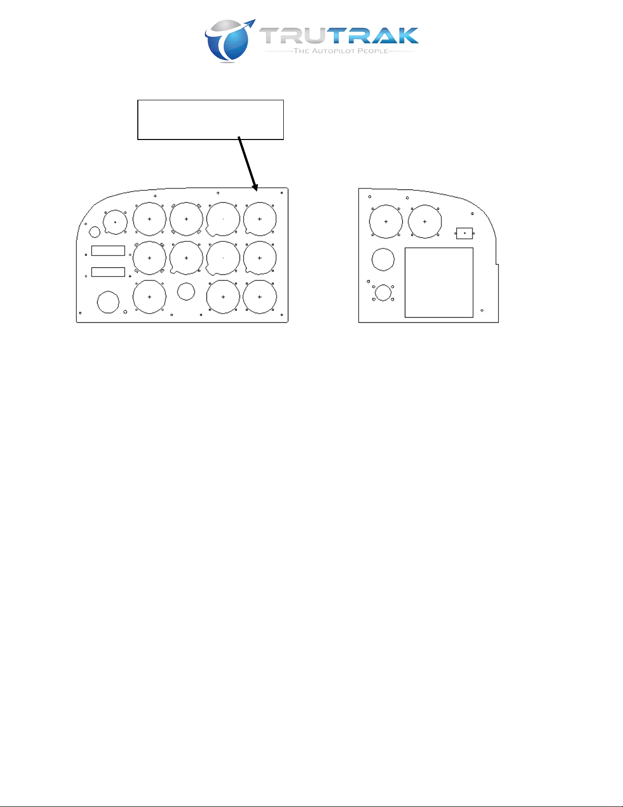
12. Install% Vizion% Limitations% Placard% (Trutrak% P/N% 8300-092)% near% the% Vizion%
autopilot.%%A%sample%panel%with%potential%placard%location%is%shown%below:%
% %
Rev: B Vizion Install Appendix E C180, C182-
C182D, C185
TruTrak Doc: 255
10
%
%
%
%
%
%
%
%
%
%
%
%
%
%
%
%
%
%
%
%
13. Reinstall%the%instrument%panel%and%panel%overlays.%
%
14. Once% autopilot% settings% are% confirmed,% perform% autopilot% system% test% per% the%
Vizion%PMA%Installation%Guide%(TruTrak%Doc.%166).%
Potential location of
Limitations Placard

Rev: B Vizion Install Appendix E C180, C182-
C182D, C185
TruTrak Doc: 255
11
3. Cessna C180, C182-C182D, C185 Servo Installation
3.1. Roll Servo Materials List
QTY%
PART%NUMBER%
DESCRIPTION%
1%
8100-064%(12%Volt)%
OR%
8100-065%(24%Volt)%
60%in-lb%PMA%Servo%
1%
7200-091%
C172%Roll%Servo%Arm%
1%
2520-062%
41"%Push%Rod%.5"%OD%Tapped%10-32%
1%
2510-210%
0.625%L%X%0.375%OD%X%.199%ID%Alum.%Spacer%
1%
2510-208%
0.250%L%X%0.375%OD%X%0.250%ID%Alum.%Spacer%
12%
2510-192%
Rivet%MS20426A3-4%
2%
2510-051%
Small%Rod%End%Bearing%MM-3-300%
3%
2500-216%
8-32%x%3/8%Flat%Head%Socket%Cap%Screw%SS%
6%
2500-122%
MS21051-08%8-32%Anchor%Nut%
1%
2500-094%
AN3-17A%
4%
2500-081%
MS35333-39%Internal%Lock%Washer%
2%
2500-076%
AN960-10%
4%
2500-075%
AN3-3A%
6%
2500-069%
8-32%X%5/8%Screw%AN526C832R10%
1%
2500-068%
AN3-7A%
2%
2500-055%
AN345-10%
2%
2500-047%
AN970-3%Washer%
1%
2500-042%
MS20364-1032%
1%
1450-128%
18X%Lower%Roll%Bracket%
1%
1450-127%
18X%Upper%Roll%Bracket%
1%
1420-216%
Servo%Bolt%Pattern%Plate%
%

Rev: B Vizion Install Appendix E C180, C182-
C182D, C185
TruTrak Doc: 255
12
3.2. Cessna C180, C182-C182D, C185 Roll Servo Mounting Instructions
IJ4AK!!"++#G!%1-./&!(&,#!%1!,##!21#%(!,F%&-!F$),#!%1-./$)?!$(!,9*$&L&03
1. The%roll%servo%will%be%mounted%in%the%left%wing%just%forward%of%the%inboard%end%of%
the%aileron.%%%
1.1. Begin%by%removing%the%inspection%cover%on%the%lower%wing%skin%located%forward%
of%the%inboard%end%of%the%aileron.%%%
1.2. Figure%3-1shows%the%roll%servo%mounting%location%from%below%the%left%wing.
Figure 3-1!
2. The%Cessna%18X%Upper%Roll%Bracket%(P/N%1450-127)%will%be%mounted%to%the%flange%
of%the%rear%wing%spar%using%3%ea.%AN526C-832R8%screws.%
2.1. Locate%the%inboard%screw%hole%as%shown%in%Figure%3-2%on%the%upper%wing%skin.%%

Rev: B Vizion Install Appendix E C180, C182-
C182D, C185
TruTrak Doc: 255
13
Figure 3-2!
2.2. Drill%the%inboard%hole%only%at%this%time%with%a%#19%drill.%
2.3. Invert%the%Cessna%18X%Upper%Roll%Bracket%(P/N%1450-127)%on%the%upper%wing%
skin%and%cleco%the%inner%hole%on%the%bracket%to%the%hole%drilled%in%the%previous%
step.%Rotate%the%bracket%so%that%the%middle%and%outer%bracket%mounting%holes%are%
aligned%with%the%row%of%rivets%in%the%rear%wing%spar%as%shown%in%Figure%3-3.%

Rev: B Vizion Install Appendix E C180, C182-
C182D, C185
TruTrak Doc: 255
14
Figure 3-3!
2.4. Match%drill%2%holes%as%shown%in%Figure%3-3.%
2.5. Remove%the%Cessna%18X%Upper%Roll%Bracket%(P/N%1450-127)%from%the%wing%and%
deburr%the%mounting%holes%that%were%drilled.%
2.6. Temporarily%attach%the%Cessna%18X%Upper%Roll%Bracket%(P/N%1450-127)%to%the%
Servo%Bolt%Pattern%Plate%(P/N%1420-216)%using%2%ea.%AN3-3A%as%shown%in%Figure%
3-4.%
Figure 3-4!
2.7. Place%the%assembly%shown%in%Figure%3-4%in%the%wing%and%cleco%in%place%as%shown%
in%Figure%3-5.%

Rev: B Vizion Install Appendix E C180, C182-
C182D, C185
TruTrak Doc: 255
15
Figure 3-5!
2.8. Temporarily%attach%the%Cessna%18X%Lower%Roll%Bracket%(1450-128)%to%the%Servo%
Bolt%Pattern%Plate%(P/N%1420-216)%using%2%ea.%AN3-3A%as%shown%in%Figure%3-6.%
Figure 3-6!
%

Rev: B Vizion Install Appendix E C180, C182-
C182D, C185
TruTrak Doc: 255
16
2.9. Drill%Cessna%18X%Lower%Roll%Bracket%(1450-128)%mounting%holes.%
2.9.1. Align%the% lower%bracket% mounting%holes% with%row% of%rivets% on%
the%lower%spar%flange.%%%
2.9.2. Match% drill% the% outboard% mounting% hole% using% a% #19% bit% from%
inside%the%wing.%%%
2.9.3. Secure%the%outboard%hole%with%a%cleco.%%%
2.9.4. Match%drill%the%remaining%2%holes%on%the%Cessna%18X%Lower%Roll%
Bracket%(1450-128)%installing%a%cleco%after%each%hole%is%drilled.%%
2.9.5. Remove% all% components% from% the% wing% and% debur% the% lower%
mounting%holes.%
2.9.6. Remove%the%Servo%Bolt%Pattern%Plate%(P/N%1420-216)%from%the%
Cessna%18X%Upper%Roll%Bracket%(P/N%1450-127).%
2.10. Install%anchor%nuts%in%the%Cessna%18X%Upper%Roll%Bracket%(P/N%1450-127)%and%
Drill%Cessna%18X%Lower%Roll%Bracket%(1450-128).%Rivet%3%ea.%MS21051-08%anchor%
nuts%in%place%using%6%ea.%MS20426AD3-4%rivets%on%each%bracket.%
2.11. Attach%the%Cessna%172%Roll%Servo%Arm%(P/N%7200-091)%to%the%60%inch/lb%PMA%
servo% (P/N% 8100-064% for% 12% volt% or% P/N% 8100-065% for% 24% volt)% using% the%
provided%8-32%x%3/8”%flat%head%screws.%%Use%blue%threadlocker%(Loctite%242%or%
equivalent)%and%torque%the%screws%to%18-20%in-lb.%
2.12. Allow%a%sufficient%service%loop%and%trim%the%roll%servo%wiring%harness%to%length.%
2.13. Terminate%the%roll%servo%wiring%harness%per%the%Vizion%wiring%diagram%in%the%
Vizion% PMA% Installation% Guide% (TruTrak% Doc.% 166)% and% install% the% 9% Pin%
Connector%Backshell%(2100-010).%
2.14. Place% the% Cessna% 18X% Upper% Roll% Bracket% (P/N% 1450-127)% and% Cessna% 18X%
Lower%Roll%Bracket%(1450-128)%in%the%wing%in%approximately%the%final%mounting%
position%but%do%not%secure%them%to%the%wing.%
2.15. Connect%the%roll%servo%wiring%harness%connector%to%the%roll%servo.%
2.16. Place%the%roll%servo%assembly%in%the%wing%and%loosely%attach%it%to%the%Cessna%
18X% Upper% Roll% Bracket% (P/N% 1450-127)% and% Cessna% 18X% Lower% Roll%Bracket%
(1450-128)%using%4%ea.%AN3-3A%bolts%with%MS35333-39%lock%washers%and%blue%
threadlocker% (Loctite242% or% equivalent).% The% next% steps% must% be% performed%
quickly%so%that%the%threadlocker%does%not%begin%to%cure%prior%to%final%torqueing.%
The% Cessna% 172% Roll% Servo% Arm% (P/N% 7200-091)% should% be% oriented% upward%
between%the%servo%stops.%
2.17. Align%the%Cessna%18X%Upper%Roll%Bracket%(P/N%1450-127)%with%the%holes%in%the%
upper%spar%and%start%3%ea.%AN526C-832R8%screws%in%the%associated%anchor%nuts.%
2.18. Align% the% Cessna% 18X% Lower% Roll% Bracket% (1450-128)%with% the% holes% in% the%
upper%spar%and%start%3%ea.%AN526C-832R8%screws%in%the%associated%anchor%nuts.%
2.19. Fully%tighten%the%upper%and%lower%AN526C-832R8%mounting%screws.%
2.20. Torque%the%4%AN3-3A%servo%mounting%bolts%to%20-25%in-lb.%
2.21. Remove%the%inspecting%cover%near%the%left%aileron%bellcrank.%%
2.22. Loosen% one% of% the% aileron% cable% turnbuckles% to% allow% for% easy% removal% and%
replacement%of%the%bolt%connecting%the%aileron%cable%to%the%bellcrank.%
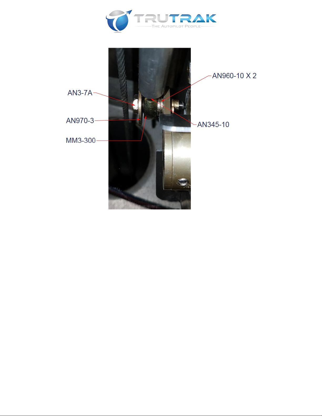
2.23. Remove%the%rear%aileron%cable%bolt%from%the%left%aileron%bellcrank%and%replace%
with%hardware%as%shown%in%Figure%3-7.%Torque%the%AN-3%bolt%to%20-25%in-lb.%

Rev: B Vizion Install Appendix E C180, C182-
C182D, C185
TruTrak Doc: 255
17
Figure 3-7!
2.24. Tension%the%aileron%cable%according%to%the%aircraft%service%manual.%
IJ4AK!5-1+&-!9,2#&!%&)($1)!$(!&((&)%$,#!F1-!+-1+&-!,/%1+$#1%!+&-F1-',)9&H!M(&!
,!%&)($1'&%&-!%1!L&-$FG!9,2#&!%&)($1)3!
2.25. Verify%that%aileron%rigging%is%correct%according%to%the%aircraft%service%manual%
and%adjust%as%needed.%
2.26. Safety%wire%the%aileron%cable%turnbuckle.%
2.27. Fully%thread%an%AN345-10%on%a%MM3-300%rod%end%bearing%then%partially%thread%
the%MM3-300%rod%end%bearing%in%one%end%of%the%41”%push%rod%(2520-062).%
2.28. Insert%the%push%rod%assembly%in%the%aileron%bellcrank%inspection%hole%with%the%
rod%end%bearing%going%toward%the%roll%servo.%
2.29. Ensure%that%the%aileron%cable%is%not%wrapped%around%the%41”%push%rod%(2510-
062)% then% partially% thread% the% MM3-300% rod% end% attached% to% the% aileron%
bellcrank%in%the%outboard%end%of%the%push%rod.%
2.30. Have%an%assistant%hold%the%yoke%in%the%full%right%position%and%rotate%the%servo%
arm%against%the%outboard%stop%on%the%roll%servo%bracket.%
2.31. Thread%the%MM-3-300%rod%end%bearing%into%the%servo%end%of%the%pushrod%until%
the%pushrod%is%the%correct%length%to%align%with%the%drive%point%on%the%servo%arm.%
2.32. Verify%that%the%control%cable%is%not%twisted%around%the%pushrod.%%
2.33. Attach%the%pushrod%assembly%to%the%Cessna%172%Roll%Servo%Arm%(P/N%7200-
091)%as%shown%in%Figure%3-8%and%torque%to%20-25%in-lb.%
Rev: B Vizion Install Appendix E C180, C182-
C182D, C185
TruTrak Doc: 255
18
Figure 3-8!
2.34. Apply%blue%threadlocker%(Loctite242%or%equivalent)%to%the%threaded%shank%of%
both%MM3-300%rod%ends.%Rotate%the%pushrod%until%the%rod%end%bearings%on%each%
end%are%threaded%in%equally%then%tighten%the%jam%nuts%to%20-25%in-lb.%%%
2.35. Move%the%yoke%throughout%the%full%range%of%travel%and%check%for%binding%in%the%
rod%end%bearings.%%If%binding%exists%adjust%the%rod%end%bearings%and%jam%nuts%to%
eliminate%it.%
2.36. A)(/-&! %*,%! ,$-9-,F%! (%1+(! ,-&! 91)%,9%&0! +-$1-! %1! (&-L1! (%1+(3! ! "0N/(%!
#&)?%*! 1F! +/(*-10! ,(! )&&0&0! /)%$#! (&-L1! (%1+(! ,-&! )1%! 91)%,9%&0! 8*&)!
91)%-1#(!,-&!'1L&0!%1!21%*!&)0(!1F!%-,L!
2.37. Verify%that%the%servo%and%pushrod%motion%are%unobstructed%throughout%the%full%
control%travel.%%Once%wiring%harness%is%installed,%ensure%that%the%wiring%harness%
is%properly%secured%to%prevent%interference.!
2.38. "++#G!%1-./&!(&,#!%1!,##!21#%(!,F%&-!F$),#!%1-./&$)?!$(!,9*$&L&03!
%
!%

Rev: B Vizion Install Appendix E C180, C182-
C182D, C185
TruTrak Doc: 255
19
3.3. Pitch Servo Materials List
QTY%
PART%NUMBER%
DESCRIPTION%
1%
8100-064%(12%Volt)%
OR%
8100-065%(24%Volt)%
60%in-lb%PMA%Servo%
1%
7200-112%
Early%Model%18X%Pitch%Push%Rod%
1%
7200-106%
2.75"%PMA%Servo%Arm%Assembly%
1%
6000-064%
Sheathed%Microfit%6%Pos%Cable%Asm%1M%
10%
6000-067%
Self-Adhesive%Cable%Tie%Anchor%1"%Square%
1%
2510-081%
MM-4%Rod%End%Bearing%
1%
2510-051%
Small%Rod%End%Bearing%MM-3-300%
3%
2500-216%
8-32%x%3/8%Flat%Head%Socket%Cap%Screw%SS%
3%
2500-208%
AN90-416%
1%
2500-205%
AN970-4%Washer%
1%
2500-138%
AN4-15A%
9%
2500-121%
MS20365-832%8-32%Fiberlock%Nut%
1%
2500-113%
MS20365-428%1/4-28%Fiberlock%Nut%
4%
2500-081%
MS35333-39%Internal%Lock%Washer%
2%
2500-076%
AN960-10%
4%
2500-075%
AN3-3A%
9%
2500-069%
8-32%X%5/8%Screw%AN526C832R10%
1%
2500-068%
AN3-7A%
1%
2500-055%
AN345-10%
1%
2500-054%
AN315-4%
1%
2500-047%
AN970-3%Washer%
1%
1450-129%
Early%18X%Pitch%Bracket%

Rev: B Vizion Install Appendix E C180, C182-
C182D, C185
TruTrak Doc: 255
20
3.4. Cessna C180, C182-C182D, C185 Pitch Servo Mounting Instructions
1. The%pitch%servo%will%be%mounted%in%the%aft%fuselage%as%shown%in%Figure%3-9.%
%
Figure 3-9
.%
2. Remove%the%baggage%compartment%bulkhead%to%access%the%rear%fuselage.%
3. Remove%the%rear%inspection%cover%on%the%bottom%of%the%fuselage.%
4. Rotate%the%Early%18X%Pitch%Bracket%(1450-129)%so%that%the%long%flange%of%the%
bracket%is%toward%the%left%of%the%aircraft.%Place%the%forward%edge%of%the%Early%
18X%Pitch%Bracket%(1450-129)%4.25”%aft%of%station%172.00”%and%2.25”%left%of%the%
centerline%on%the%lower%skin%inside%the%aft%fuselage.%The%elevator%cables%provide%
a%good%reference%of%the%centerline%of%the%aircraft.%
This manual suits for next models
3
Table of contents
Other TruTrak Autopilot System manuals


