TSAT 3500 User manual

Product: U3510A Revision: 02P
September 2020
TSAT - Telemetry and data transfer via SATellite
TSAT 3500 User Guide
HUB Station and Remote Terminal
Installation, Operation and Maintenance
Guide

TSAT 3500 - Telemetry and data transfer via SATellite
Installation, Operation and Maintenance Guide, September 2020 Page 2 of 40
Document Status
Product description: HUB Station and Remote Terminal Installation Operation and
Maintenance Guide
Revision
Date
Reason for change
Archive
1
10.08.2020
First Revision
U3510A01
2
17.09.2020
Minor updates: Ch 7: Interfaces
U3510A02
Approved
SHA
Date
17.09.2020
Checked
CBE
Date
17.09.2020
Further information about TSAT 2000/2100/2150/3000/3500 can be obtained from:
TSAT AS
Martin Linges vei 25
N-1364 FORNEBU
NORWAY
Telephone: +47 66 77 44 40
TSAT AS makes no warranty of any kind with regard to this material, including, but not limited to, the implied warranties of
merchantability and fitness for a particular purpose. TSAT AS assumes no responsibility for any errors that may appear in
this document. TSAT AS makes no commitment to update nor to keep current the information contained in this document.
Specifications and procedures may change at any time without notice. No part of this document may be copied or
reproduced in any form or by any means without prior written consent of TSAT AS.
Brand names used in this document are the property of their respective owners. Company and product names are
trademarks or registered trademarks of their respective companies.
Copyright ©2020, TSAT AS. All rights reserved.

TSAT 3500 - Telemetry and data transfer via SATellite
Installation, Operation and Maintenance Guide, September 2020 Page 3 of 40
Documentation Comment Form
TSAT AS encourages you to comment on the documentation supplied with our products. This
information helps us to provide quality products to meet your needs.
Edition Date: September 2020
Product: U3510A, revision 02
Please comment on the correctness, completeness, clarity, organisation and usefulness of the
manual.
________________________________________________________________________
________________________________________________________________________
________________________________________________________________________
________________________________________________________________________
________________________________________________________________________
If you find errors in the manual, please record the page numbers and describe the errors.
________________________________________________________________________
________________________________________________________________________
________________________________________________________________________
________________________________________________________________________
________________________________________________________________________
Thank you for your help.
Name___________________________________________________________________
Title_____________________________________________________________________
Company_________________________________________________________________
Address__________________________________________________________________
________________________________________________________________________
Phone (________)________________________________________________________
Mail to TSAT AS, Martin Linges vei 25, 1364 FORNEBU

TSAT 3500 - Telemetry and data transfer via SATellite
Installation, Operation and Maintenance Guide, September 2020 Page 4 of 40
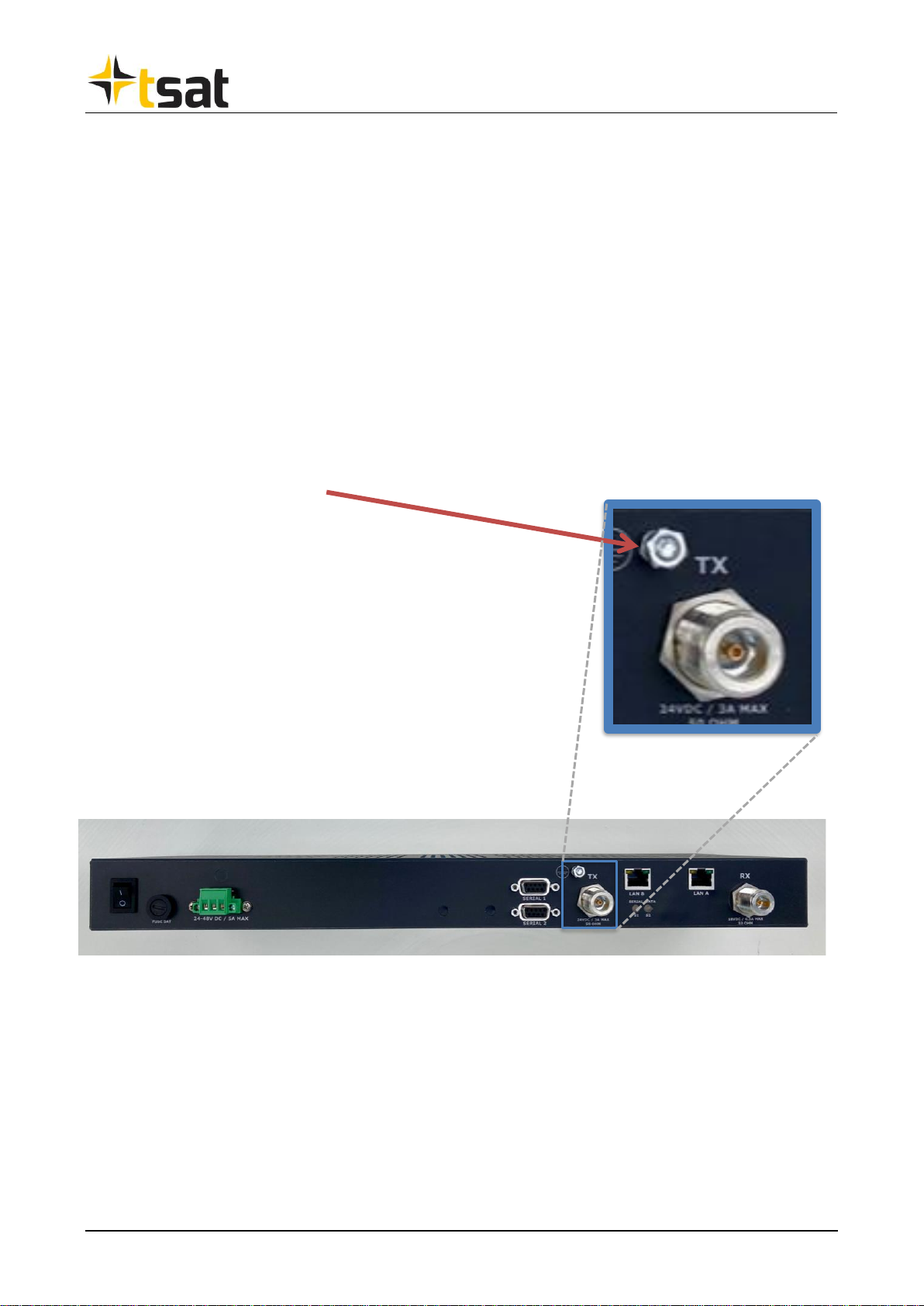
Protective Grounding
Protective grounding –here shown for rack-mount version.
M4 SCREW:
PROTECTIVE
GROUNDING

TSAT 3500 - Telemetry and data transfer via SATellite
Installation, Operation and Maintenance Guide, September 2020 Page 5 of 40
Table of Contents
1INTRODUCTION......................................................................................................................................... 7
1.1 SCOPE.......................................................................................................................................................... 7
1.2 TSAT 3500 SYSTEM INTRODUCTION .......................................................................................................... 7
2HUB STATION AND REMOTE TERMINAL SITE REQUIREMENTS .............................................. 9
2.1 INTRODUCTION............................................................................................................................................ 9
2.2 ANTENNA SITE REQUIREMENTS................................................................................................................... 9
2.2.1 Site elevation and azimuth angles .......................................................................................................... 9
2.2.2 Signal path obstruction .......................................................................................................................... 9
2.3 ANTENNA MOUNT REQUIREMENTS............................................................................................................ 10
2.4 ANTENNA MOUNT METHODS ..................................................................................................................... 10
2.4.1 Pole mount ........................................................................................................................................... 10
2.4.2 Wall mount / Ground mount................................................................................................................. 10
2.5 CABLE REQUIREMENTS.............................................................................................................................. 11
2.5.1 Data cable requirements ...................................................................................................................... 11
2.5.2 BUC/LNB cable requirements TSAT 3500........................................................................................... 11
2.5.3 DC Power cables.................................................................................................................................. 11
3HUB STATION INSTALLATION ........................................................................................................... 12
3.1 INTRODUCTION.......................................................................................................................................... 12
3.2 ANTENNA UNIT ASSEMBLY ........................................................................................................................ 13
3.3 ANTENNA POINTING .................................................................................................................................. 13
3.3.1 Introduction.......................................................................................................................................... 13
3.3.2 Antenna pointing procedure................................................................................................................. 14
3.4 RF FRONT END MOUNTING ....................................................................................................................... 15
3.4.1 RF Front End assembly........................................................................................................................ 15
3.4.2 RF Front End rotation adjustment ....................................................................................................... 16
3.5 MAIN UNIT MOUNTING ............................................................................................................................. 19
3.6 PROTECTIVE GROUNDING .......................................................................................................................... 19
3.7 SUPERVISORY TERMINAL INSTALLATION .................................................................................................. 19
3.8 HUB STATION MODULES INTERCONNECTION ON TSAT 3500 .................................................................. 20
4REMOTE TERMINAL INSTALLATION .............................................................................................. 21
4.1 INTRODUCTION.......................................................................................................................................... 21
4.2 ANTENNA UNIT ASSEMBLY ....................................................................................................................... 22
4.3 ANTENNA POINTING .................................................................................................................................. 22
4.4 RF FRONT END MOUNTING ....................................................................................................................... 22
4.5 MAIN UNIT MOUNTING ............................................................................................................................. 22
4.6 REMOTE TERMINAL MODULES INTERCONNECTION TSAT 3500 ................................................................ 23
4.7 PROTECTIVE GROUNDING .......................................................................................................................... 23
5HUB STATION OPERATION .................................................................................................................. 24
5.1 PRE-OPERATIONAL REQUIREMENTS........................................................................................................... 24
5.2 MAIN UNIT CONFIGURATION ..................................................................................................................... 24
5.3 SUPERVISORY TERMINAL CONFIGURATION ............................................................................................... 24
5.4 HUB STATION POWER-UP ......................................................................................................................... 24
5.5 CIRCUIT-SWITCHED PROTOCOL OPERATION............................................................................................... 25
5.6 LAN (TCP/IP) OPERATION........................................................................................................................ 25
5.7 SUPERVISORY TERMINAL OPERATION....................................................................................................... 25
5.7.1 Introduction.......................................................................................................................................... 25
5.7.2 Network Status monitoring................................................................................................................... 25
5.7.3 Logging of statistical data.................................................................................................................... 25
5.8 ADDING NEW REMOTE TERMINALS ........................................................................................................... 25
5.9 REMOVING REMOTE TERMINALS FROM THE NETWORK ............................................................................. 25

TSAT 3500 - Telemetry and data transfer via SATellite
Installation, Operation and Maintenance Guide, September 2020 Page 6 of 40
6REMOTE TERMINAL OPERATION..................................................................................................... 26
6.1INTRODUCTION.......................................................................................................................................... 26
6.2 REMOTE TERMINAL CONFIGURATION ....................................................................................................... 26
6.3 REMOTE TERMINAL POWER-UP ................................................................................................................. 26
6.4 APPLICATION PORT OPERATION ................................................................................................................. 27
6.4.1 Async. ports.......................................................................................................................................... 27
6.4.2 LAN ports ............................................................................................................................................. 27
7INTERFACE SPECIFICATIONS ............................................................................................................ 28
7.1 TSAT 3500 /TSAT 3500 PRO ................................................................................................................. 28
8HUB STATION AND REMOTE TERMINAL MAINTENANCE ........................................................ 31
8.1 INTRODUCTION.......................................................................................................................................... 31
8.2 NORMAL MAINTENANCE............................................................................................................................ 31
8.3 MAIN UNIT SOFTWARE /FIRMWARE UPGRADES. ....................................................................................... 31
8.4 SUPERVISORY TERMINAL SERVICE/MAINTENANCE.................................................................................... 31
9TROUBLESHOOTING ............................................................................................................................. 32
9.1 SUPERVISORY TERMINAL .......................................................................................................................... 32
9.2 HARDWARE PROBLEMS ............................................................................................................................. 33
10 CHECK LISTS TSAT 3500 ....................................................................................................................... 34
11 APPENDIX:................................................................................................................................................. 40
11.1 TECHNICAL SPECIFICATIONS ..................................................................................................................... 40
11.2 HUB ANTENNA ASSEMBLY MANUAL IF APPLICABLE................................................................................. 40
11.3 RT ANTENNA ASSEMBLY MANUAL IF APPLICABLE .................................................................................... 40

TSAT 3500 - Telemetry and data transfer via SATellite
Installation, Operation and Maintenance Guide, September 2020 Page 7 of 40
1Introduction
1.1 Scope
This document is intended for giving system engineers, support engineers, and installation and
service personnel the necessary information to plan, install, operate and maintenance a TSAT
network. A brief trouble-shooting guide is also included.
The Supervisory Terminal and Network Management System is described in the "Supervisory
Terminal User Guide".
1.2 TSAT 3500 System Introduction
The TSAT 3500 satellite communication network is dedicated to low-to-medium data rate
communication via satellite. The Remote Terminals are controlled by one common HUB Station in a
full duplex closed star network configuration, see Figure 1-1. The unique design of TSAT 3500
introduces low-cost solutions to traditional problem areas in low data rate satellite communication,
such as frequency stability, phase noise, and interference requirements. Flexible interface and
protocol options offer cost-effective communication solutions for data collection, remote monitoring
and control and transaction applications.
Hub Station
1.8->
Remote Terminals
0.9-1.8 m
9.6kbps –833kbps
Figure 1-1 TSAT 3500 Closed Network
•Low data rate: 9.6kbps –833kbps enables low transponder load.
•The outbound link, from the HUB to the RT’s, is running continuously, addressing
and commanding the Remote Terminals.
•The Remote Terminals share one or several inbound links either by time division
multiplexing or by random access.
•Any conventional Ku-band or C-band communication transponder can be used.
•Closed network: TSAT 3500 is a dedicated, private network.
•Mesh network, optionally

TSAT 3500 - Telemetry and data transfer via SATellite
Installation, Operation and Maintenance Guide, September 2020 Page 8 of 40
The TSAT 3500 design allows a complete HUB station comparable in size and complexity to
traditional VSAT’s (Very Small Aperture Terminals). Because of the extremely low-cost HUB station,
TSAT 3500 requires low investments in earth station equipment. The efficient utilisation of satellite
power and bandwidth gives low operational costs, enabling cost-effective solutions even for small
networks.
The modular design enables flexibility for future extension of network capacity. Adding more inbound
link frequencies, requiring only the addition of an extra Main Unit in the HUB Station will increase the
inbound link capacity. If the network grows beyond the capacity of the outbound link, the network
can be divided into sub-networks by adding new outbound links.
Possible applications include:
•Collection and distribution of data, i.e. environmental, ecological and security surveillance.
•Remote monitoring and control (SCADA), e.g. within electrical generation, transmission and
distribution, oil and gas pipelines, water management.
•Transaction oriented networks, i.e. credit-card verification, on-line betting, automatic teller
machines (ATM).
•Collection of seismological data
Figure 1-2 TSAT 3500 Network Configuration.
Supervisory Terminal
Remote Terminal
Asynch serial
Asynch serial
Asynch serial
interface (RS 232,
option RS422/485)
Network Management
TSAT HUB
Station
Communication protocols
HUB
Main
Unit
RT
Main
Unit
Antenna
RF Front End
Antenna
RF Front End
LAN (TCP/IP)
LAN (TCP/IP)
Ref
osc
LAN (TCP/IP)
LAN (TCP/IP)
interface (RS 232,
option RS422/485)
interface (RS 232,
option RS422/485)

TSAT 3500 - Telemetry and data transfer via SATellite
Installation, Operation and Maintenance Guide, September 2020 Page 9 of 40
2HUB Station and Remote Terminal Site Requirements
2.1 Introduction
The following sections describe the requirements for the TSAT network sites, including mechanical
requirements for the HUB Station and Remote Terminal sites, pointing direction, and wind load.
2.2 Antenna Site requirements
2.2.1 Site elevation and azimuth angles
The site elevation and azimuth angles must be known before a site survey can be performed. The
antenna site elevation and azimuth angle, and distance to the satellite, can be calculated when the
following parameters are determined.
•The location of the satellite in the geostationary orbit, normally given in degrees with
references to the zero meridian (Greenwich, London). Angle is positive towards east.
•Site longitudinal location (degrees).
•Site latitudinal location (degrees).
The required parameters are:
r m
r m
e
s
= •
= •
=
=
638 10
4 2172 10
6
7
. (
. (
(
earth radius)
distance earth center to geostationary orbit)
lattitude antenna site
longitude antenna site) - (longitude satellite position in geostationary orbit)
The antenna site elevation angle, from horizontal plane, is given by:
( ( )
( )
)
= − − arctan cos cos / / cos cos /
r r
e s 121 2
The antenna site azimuth angle, from true north, positive angle clockwise, is found from the equation:
( ) ( )
( )
a arctg tg= +180
/sin
The distance to the satellite is given by:
d r r r r
s e s e
= + −
2 2 1 2
2 cos cos /
There exist programs that would do these calculations automatically, with satellite position and site
coordinates as input.
2.2.2 Signal path obstruction
The antenna site must have an unobstructed bore sight to the satellite position in the geostationary
orbit, as shown in Figure 2-1. An obstruction inside this envelope will result in reduced signal to noise
ratio and increased transmit signal interference levels which are not compliant with ETSI and satellite
operator requirements.

TSAT 3500 - Telemetry and data transfer via SATellite
Installation, Operation and Maintenance Guide, September 2020 Page 10 of 40
2 deg.
1 deg.
5 m for 0.55 m dia.
10 m for 0.9 m dia.
10 m for 1.2 m dia.
< 100 m
> 100 m
Antenna diameter
Figure 2-1 Transmit signal path envelope
2.3 Antenna Mount requirements
To maintain compliance with ETSI and satellite operator requirements, the antenna mount must be
permanently fixed to a supporting structure that enables the antenna to maintain a stability within 0.5
degrees under normal operating conditions (for a wind speed of up to 30 m/s). In addition, the
specification given in ETSI EN 301 428 state that under the condition of 100 km/h maximum wind
speed, with gusts of 130 km/h lasting 3 seconds, the antenna or other parts of the structure shall not
show any sign of permanent distortion and shall not need repointing after the application of the wind
load. A load of 20 mm of ice coating on the antenna surface should also be considered in areas
where this condition might occur. The supporting structure should therefore be constructed with this
in mind, or existing structure should be examined carefully, before the antenna mount is assembled
2.4 Antenna mount methods
2.4.1 Pole mount
The HUB Station antenna diameter is normally 1.8m or 2.4m. The 1.8m antenna normally fits a pole
dimension of 4.5 inches(114,3mm).Other HUBantenna dimensions canalso be used. For assembly
and mounting of the HUB antenna see the description supplied with the antenna.
The Remote Terminal antenna diameter is normally 96 cm or 1.2m and uses 3-inch pole size. For
C-band, 1.8m is also often used. For assembly and mounting of the Remote Terminal antenna see
the description supplied with the antenna.
2.4.2 Wall mount / Ground mount
If a wall mount is used, the distance from the wall to the pole must allow the antenna to be rotated
sufficiently to point to the satellite position in the geostationary orbit se. With the 120 cm antenna the
distance from the wall to the pole must be 630 mm to allow pointing parallel with the wall.
See the documentation supplies with the mounts for assembling and mounting.

TSAT 3500 - Telemetry and data transfer via SATellite
Installation, Operation and Maintenance Guide, September 2020 Page 11 of 40
2.5 Cable requirements
2.5.1 Data cable requirements
See the interface specifications in chapter 7 for details.
Serial application data interfaces (Serial 1 & 2): The two asynchronous interfaces on the Main Unit
comply with the RS-232 standard, DCE pin-out. RS422/485 can be provided as an option. The cable
environmental specifications must satisfy the local conditions. The maximum cable length according
to this standard is 15 meters at 9600 bps. Practical use has shown that this length normally may be
exceeded without observable degradation up to 30 meters. However, in noisy environments even
distances of a few meters may give unreliable performance. In this case, or for long cable lengths,
the signals must be transmitted via short haul modems or data signal converters. For the use of short
haul modems, please refer to the short haul modem documentation.
LAN interfaces (LAN A & B): The LAN interfaces comply with Ethernet RJ45 standard, and is auto
negotiating, 10/100MHz, full/half duplex and auto MDI/MDIX. Screened cable must be used.
In addition, there is 1 x console port (USB-C) for m&c purposes.
2.5.2 BUC/LNB cable requirements TSAT 3500
The BUC and the LNB are connected to the Main Unit with two 50ohm coaxial cables (cable harness
kit CKA 3500). The cable specifications depend on the distance between the Main Unit and the
BUC/LNB. The cable loss must be <20dB on the TX L-band signal (950-1700MHz) and <20dB on
the Rx L-band signal (950-2150MHz). The maximum coax cable voltage loss is 0.5 V for DC power
supply. The 10 MHz reference oscillator signal is multiplexed onto the coax cable. Normally, coaxial
cables have negligible losses at 10 MHz. N-type 50ohm connectors are used on both the BUC, LNB
and Main Unit. For long distances, low-loss coaxial cables are required. The cables must satisfy the
local outdoor environmental specifications.
2.5.3 DC Power cables
The DC power cables are recommended to be 0,5mm2 up to 1,5mm2. The green plug which is
attached the main unit (HUB and RT rack mount version) must be wired according to + and –as can
be seen on connector side of modem. The cable environmental specifications must satisfy the local
conditions. The maximum cable length is 3m.

TSAT 3500 - Telemetry and data transfer via SATellite
Installation, Operation and Maintenance Guide, September 2020 Page 12 of 40
3HUB Station Installation
3.1 Introduction
This section describes the installation procedure for assembling and mounting all TSAT 3500 HUB
Station modules, including the procedure for pointing the antenna towards the satellite.
The TSAT 3500 HUB Station normally consists of the following modules, shown in fig 3-1:
1. Antenna
2. BUC Transmitter TX14x4
3. LNB Receiver RX14x0
4. HUB Main Unit Assembly MUA3542
5. Transmit/Receive coax cable assembly CKA3500
6. Supervisory Terminal Assembly
Figure 3-1 TSAT 3500 HUB Station Module
Other required units are:
•Antenna mounting structure including pole
•Data cables between application equipment and TSAT if not supplied together with the HUB
Station.
•Power supply for Main Unit

TSAT 3500 - Telemetry and data transfer via SATellite
Installation, Operation and Maintenance Guide, September 2020 Page 13 of 40
3.2 Antenna unit assembly
Assemble and mount the antenna according to the description supplied with the antenna. The
antenna-mounting pole must satisfy the antenna site requirements discussed in section 2.
3.3 Antenna pointing
3.3.1 Introduction
To point the antenna, the elevation and azimuth angles at the site must be known, see section 2.
The procedure described below assumes that a Ku-band TV carrier is available at the same
geostationary orbit position as the satellite of interest. If this is not the case, personnel familiar with
pointing antennas to satellites must operate a beacon finder or spectrum analyser.
Three parts, BUC (TX unit), LNB (Rx unit) and waveguide with LPF (Low Pass Filter) make up the
TSAT3500 RF Front End. The RF Front End are available in several versions, see table 3.1, all
combinations are legal.
On TSAT3500 HUB Main Unit the Rx L-Band connector can be used in connection with any
TSAT3500 RF Front End to monitor the received TV carrier. This connector is an option.
Frequency range (GHz)
Local oscillator (GHz)
Input/ Output frequency range (MHz)
Tx: 14.00 - 14.50
13.05
Input: 950 –1 450
Rx: 12.25 –12.75
11.30
Output: 950 –1 450
Rx: 10.95 –11.70
10.00
Output: 950 –1 450
Rx: 11.70 –12.20
10.75
Output: 950 –1 450
Table 3.1 RF Front End frequencies for TSAT 3500
For C-band and other bands, there are similar local oscillator options available to cover different
satellite frequency ranges. Note that the TSAT3500 Main Unit IF range is 950 - 1 700/ 2 150 MHz,
which together with the RF unit local oscillator frequency will determine the available satellite
frequencies for transmission/reception.
The pointing procedure is based on using a "satellite finder", an instrument for monitoring received
TV carrier levels in the Ku-band. Normally the TV sound can be monitored, and some models display
the TV picture. The signal level is displayed, allowing the antenna to be adjusted to the maximum
receive gain position. These instruments normally assume the use of standard LNBs with a local
oscillator of 10 GHz. The input frequency range is therefore normally 950 MHz to 1 700 MHz.
The TSAT RF Front End uses an PLL LNB, these LNBs needs a 10MHz external reference signal.
Most instruments used for pointing antennas do not supply this. It is therefore normally necessary to
mount a standard TV reception LNB for the antenna pointing and mount the TSAT3500 RF Front
End after the antenna is adjusted to the correct position.
Required tools and instruments
The procedure below is based on finding a TV carrier at the same geostationary orbit position, and
adjusting the antenna bore sight to give a maximum signal level. The antenna will then be at the
correct position also for the TSAT 3500 carriers. It is also necessary to adjust the rotational angle of
the RF Front End to adjust the cross polar interference level to the specified level. The ETSI
specifications state that the polarisation angle should be aligned with an accuracy better than 1
degree, corresponding to a cross polar level lower than - 35 dBc (see also section 3.4.2.).

TSAT 3500 - Telemetry and data transfer via SATellite
Installation, Operation and Maintenance Guide, September 2020 Page 14 of 40
The recommended equipment for pointing the antenna is:
•Satellite finder, e.g. Promax Sat Hunter
•Compass with accuracy better than 1 degree. Recommendation Suunto type: KB-14 360R.
•Knowledge of true north to magnetic north angle
•Map over the antenna site area
•Knowledge of TV carriers in the same and adjacent satellite positions
•Inclinometer with a bar/rod slightly longer than the antenna diameter, resolution better than 1
degree's degree and accuracy +/- 0.25 degree. Recommendation: Suunto type: PM-5 360PC.
•Low cost universal LNB that can be mounted to the antenna horn wave guide
•Recommended tools for adjusting the RF Front End rotation (cross-polar adjustment):
Inclinometer with bar/rod suitable for measuring the RF Front End rotation angle
3.3.2 Antenna pointing procedure
3.3.2.1 Pre-adjustment of antenna
Determining the elevation and azimuth of the antenna is described in section 2. The antenna
elevation can be adjusted to the approximate position by using the inclinometer and a bar across the
main antenna reflector, as indicated in figure 3-2. The correspondence between the main antenna
reflector and bore sight angle of the antenna differs slightly from antenna to antenna and can be
found in the antenna assembly description.
The antenna azimuth angle can be adjusted to the approximate position by using a compass. The
magnetic field conditions of the site may influence the compass strongly. If the site is located near
large buildings, the compass direction may be completely wrong, with large fluctuations over only a
few meters distance. To check this, move the compass a few meters to each side. A map over the
site may be used to establish a reference direction. The azimuth angle of interest can then be
adjusted by using the compass to rotate the antenna relative to the reference direction.
The antenna should now be pointing approximately in the right direction (within a few degrees).
Figure 3-2 Antenna elevation pre-adjustment
= angle between main reflector and antenna bore sight
= inclinometer angle
= site elevation angle

TSAT 3500 - Telemetry and data transfer via SATellite
Installation, Operation and Maintenance Guide, September 2020 Page 15 of 40
3.3.2.2 Satellite acquisition
Mount the TV reception LNB to the antenna horn. Connect the LNB to the satellite finder instrument
and adjust the satellite finder to monitor an available TV carrier at the satellite position. (Please refer
to the manual for the LNB and satellite finder instrument for detailed operating instructions). Rotate
the antenna back and forth a few degrees in the azimuth plane and observe if the TV carrier of
interest is received. If no carrier is received, adjust the satellite finder to receive other TV carrier. If
the result is still negative, carefully repeat the procedure for pre-adjusting the antenna, or adjust the
antenna to point to an adjacent satellite with a known TV carrier, i.e. ASTRA. When a known satellite
is found, this position can be used as reference.
When the correct carrier on the correct satellite is found, peak the signal level by adjusting the
antenna carefully in both the elevation and azimuth plane several times, since the adjusting one of
the planes also slightly effect the direction in the other plane.
Fix the antenna bracket in the position giving the maximum signal level. Ensure that the maximum
signal level is received also after the antenna bracket has been fixed. Remove the LNB from the
antenna horn. The antenna should now be pointing with a maximum gain towards the satellite of
interest.
3.4 RF Front End Mounting
3.4.1 RF Front End assembly
The BUC and LNB are mounted to the OMT using supplied screws, the LNB must be mounted on
the filtered end. Transmit and receive are mounted in a 90 degrees angleto each other. One example
of mounting is shown in Figure 3-3 RF Front End assembly, OMT and filter are normally supplied
with the antenna and are only shown here as example.
Make sure that there are O-rings between all parts.
See the antenna assembly instruction for OMT and feed horn assembly.
Figure 3-3 RF Front End assembly (example for illustration only)
LNB
BUC
OMT
Filter

TSAT 3500 - Telemetry and data transfer via SATellite
Installation, Operation and Maintenance Guide, September 2020 Page 16 of 40
3.4.2 RF Front End rotation adjustment
The satellite transponder operates with linear polarisation, either horizontal (H) or vertical (V). The
polarisation must therefore be known when installing the RF Front End. The orientation of the BUC
in vertical polarisation for TX is shown in figure 3-4.
Figure 3-4 Orientation of BUC in vertical polarisation for TX
RF Front End rotation adjustment for minimising cross-polar radiation level.
The RF Front End must be set at the correct rotation angle with an accuracy within 1 degree,
corresponding to a cross polar level below -35 dBc. The antenna is normally delivered with a fixed
mount. In this case, the angle is a function of the antenna site position and the satellite position.
figure 3-5 displays graphs for the cross-polar rotation angle with reference to the gravitation vector,
as a function of the azimuth angle, with the elevation as the parameter. The same data is tabulated
in table 3-2.
Normally, the horizontal polarisation direction is parallel to the geostationary orbit, and vertical
polarisation is then perpendicular to the geostationary orbit. This orientation is assumed in fig 3-5
and table 3-2. Some satellites have a polarisation offset that also must be taken into account. Before
a new satellite is taken into use, the satellite operator should confirm this information.

TSAT 3500 - Telemetry and data transfer via SATellite
Installation, Operation and Maintenance Guide, September 2020 Page 17 of 40
Figure 3-5 Cross-polar rotation angle as a function of the azimuth angle, with the elevation as
the parameter.
The RF Front End rotation is adjusted as shown in fig 3-4 by laying an inclinometer across the RF
Front End and adjusting the rotation angle according to table 3-2. Linear interpolation can be used
for values not tabulated.
Recommended inclinometer Suunto type: PM-5 360 PC.
Follow the procedure below after you have found the correct satellite (section 3.3).
1. Use table 3.2 to determine the RF Front End angle. Remember to take into account any offset
angle given by satellite operator.
2. Adjust the antenna to set the RF Front End close to horizontal position.
3. Use the inclinometer and adjust the RF Front End to the angle from point 1. Use a knife to put a
thin mark on the feed horn and feed horn-mounting bracket.
4. Adjust the antenna to the correct elevation angle. Use another LNB if necessary.
5. If the RF Front End has been removed when doing point 4, adjust the RF Front End to the mark
in point 3.
6. Tighten the feed horn to the bracket.
RF Front End Tilt
-10,0
0,0
10,0
20,0
30,0
40,0
50,0
60,0
70,0
80,0
0
4
8
12
16
20
24
28
32
36
40
44
48
52
56
60
64
68
72
76
80
Satellite pos. - Earth st. Longitude
Earth st. lattitude (deg) 10
Earth st. lattitude (deg) 20
Earth st. lattitude (deg) 30
Earth st. lattitude (deg) 40
Earth st. lattitude (deg) 50
Earth st. lattitude (deg) 60
Earth st. lattitude (deg) 70

TSAT 3500 - Telemetry and data transfer via SATellite
Installation, Operation and Maintenance Guide, September 2020 Page 18 of 40
If satellite position is east of earth station longitude: "Turn right"
If satellite position is west of earth station longitude: "Turn left"
Earth st. lattitude (deg)
10 15 20 25 30 35 40 45 50 55 60 65 70 75 80
0 0,0 0,0 0,0 0,0 0,0 0,0 0,0 0,0 0,0 0,0 0,0 0,0 0,0 0,0 0,0
2 11,2 7,4 5,5 4,3 3,4 2,8 2,4 2,0 1,7 1,4 1,1 0,9 0,7 0,5 0,3
4 21,6 14,6 10,8 8,5 6,9 5,7 4,7 4,0 3,3 2,8 2,3 1,8 1,4 1,1 0,7
6 30,6 21,3 16,0 12,6 10,2 8,4 7,0 5,9 5,0 4,1 3,4 2,8 2,2 1,6 1,0
8 38,2 27,4 20,9 16,6 13,5 11,2 9,3 7,9 6,6 5,5 4,5 3,7 2,9 2,1 1,4
10 44,5 32,9 25,4 20,4 16,7 13,8 11,6 9,8 8,2 6,9 5,7 4,6 3,6 2,6 1,7
12 49,7 37,7 29,7 23,9 19,7 16,4 13,8 11,6 9,8 8,2 6,8 5,5 4,3 3,1 2,1
14 53,9 42,0 33,5 27,3 22,6 18,9 16,0 13,5 11,4 9,5 7,9 6,4 5,0 3,7 2,4
16 57,3 45,7 37,0 30,5 25,4 21,4 18,1 15,3 12,9 10,8 8,9 7,2 5,7 4,2 2,7
18 60,2 49,0 40,2 33,4 28,0 23,7 20,1 17,0 14,4 12,1 10,0 8,1 6,3 4,7 3,1
20 62,7 51,8 43,1 36,1 30,5 25,9 22,0 18,7 15,9 13,3 11,0 9,0 7,0 5,2 3,4
22 64,7 54,3 45,7 38,6 32,8 28,0 23,9 20,4 17,3 14,5 12,1 9,8 7,7 5,7 3,7
24 66,5 56,5 48,0 40,9 35,0 30,0 25,7 21,9 18,7 15,7 13,1 10,6 8,3 6,1 0,0
26 68,0 58,5 50,2 43,1 37,0 31,9 27,4 23,5 20,0 16,9 14,0 11,4 9,0 6,6 0,0
28 69,3 60,2 52,1 45,0 38,9 33,6 29,0 24,9 21,3 18,0 15,0 12,2 9,6 7,1 0,0
Sattelite pos. 30 70,5 61,7 53,8 46,8 40,7 35,3 30,6 26,3 22,5 19,1 15,9 13,0 10,2 7,5 0,0
-32 71,5 63,0 55,4 48,5 42,3 36,9 32,0 27,7 23,7 20,1 16,8 13,7 10,8 8,0 0,0
earth st. pos. 34 72,4 64,3 56,8 50,0 43,9 38,4 33,4 29,0 24,9 21,2 17,7 14,4 11,4 8,4 0,0
(degrees) 36 73,2 65,4 58,1 51,4 45,3 39,8 34,8 30,2 26,0 22,1 18,5 15,1 11,9 8,8 0,0
38 73,9 66,3 59,2 52,6 46,6 41,1 36,0 31,3 27,1 23,1 19,3 15,8 12,5 9,2 0,0
40 74,6 67,2 60,3 53,8 47,8 42,3 37,2 32,5 28,1 24,0 20,1 16,5 13,0 9,6 0,0
42 75,1 68,0 61,3 54,9 48,9 43,4 38,3 33,5 29,0 24,8 20,9 17,1 13,5 10,0 0,0
44 75,6 68,7 62,1 55,9 50,0 44,5 39,3 34,5 29,9 25,7 21,6 17,7 14,0 10,4 0,0
46 76,1 69,4 62,9 56,8 51,0 45,5 40,3 35,4 30,8 26,5 22,3 18,3 14,5 10,8 0,0
48 76,5 70,0 63,7 57,6 51,9 46,4 41,2 36,3 31,6 27,2 23,0 18,9 14,9 11,1 0,0
50 76,9 70,5 64,4 58,4 52,7 47,3 42,1 37,1 32,4 27,9 23,6 19,4 15,4 11,5 0,0
52 77,3 71,0 65,0 59,1 53,5 48,1 42,9 37,9 33,2 28,6 24,2 19,9 15,8 0,0 0,0
54 77,6 71,5 65,5 59,8 54,2 48,8 43,6 38,6 33,8 29,2 24,8 20,4 16,2 0,0 0,0
56 77,9 71,9 66,1 60,4 54,8 49,5 44,3 39,3 34,5 29,8 25,3 20,9 16,6 0,0 0,0
58 78,1 72,3 66,5 60,9 55,4 50,1 45,0 40,0 35,1 30,4 25,8 21,3 16,9 0,0 0,0
60 78,4 72,6 67,0 61,4 56,0 50,7 45,6 40,5 35,7 30,9 26,3 21,7 17,3 0,0 0,0
62 78,6 72,9 67,4 61,9 56,5 51,2 46,1 41,1 36,2 31,4 26,7 22,1 17,6 0,0 0,0
64 78,8 73,2 67,7 62,3 57,0 51,7 46,6 41,6 36,7 31,9 27,1 22,5 0,0 0,0 0,0
66 78,9 73,5 68,0 62,7 57,4 52,2 47,1 42,0 37,1 32,3 27,5 22,8 0,0 0,0 0,0
68 79,1 73,7 68,3 63,0 57,8 52,6 47,5 42,5 37,5 32,7 27,9 0,0 0,0 0,0 0,0
70 79,2 73,9 68,6 63,3 58,1 53,0 47,9 42,9 37,9 33,0 28,2 0,0 0,0 0,0 0,0
72 79,4 74,1 68,8 63,6 58,4 53,3 48,2 43,2 38,2 33,3 0,0 0,0 0,0 0,0 0,0
74 79,5 74,2 69,0 63,8 58,7 53,6 48,5 43,5 38,5 0,0 0,0 0,0 0,0 0,0 0,0
76 79,6 74,4 69,2 64,0 58,9 53,8 48,8 43,8 0,0 0,0 0,0 0,0 0,0 0,0 0,0
78 79,7 74,5 69,3 64,2 59,1 54,1 0,0 0,0 0,0 0,0 0,0 0,0 0,0 0,0 0,0
80 79,7 74,6 69,5 0,0 0,0 0,0 0,0 0,0 0,0 0,0 0,0 0,0 0,0 0,0 0,0
82 0,0 0,0 0,0 0,0 0,0 0,0 0,0 0,0 0,0 0,0 0,0 0,0 0,0 0,0 0,0
Table 3-2 RF Front End tilt relative to vertical line
The "right" and "left" rotation is seen from the front of the antenna.

TSAT 3500 - Telemetry and data transfer via SATellite
Installation, Operation and Maintenance Guide, September 2020 Page 19 of 40
3.5 Main Unit Mounting
The Main Unit can be mounted in several different ways. Without any brackets it can be placed on a
table-top. Optionally, the Main Unit can be equipped with brackets for 19” rack mount, or wall mount.
The standard Main Unit must be mounted indoors, but outdoor cabinet is an option.
Fig 3-6: Hub Main Unit front and rear view
3.6 Protective grounding
The Main Unit must be properly connected to earth to the M4mm screw with grounding mark on the
connector wall. See page 4.
3.7 Supervisory Terminal Installation
The Supervisory Terminal is a standard Windows PC or server, and is normally powered by 220
VAC. The Supervisory Terminal program is normally pre-installed. If this is not the case, please refer
to the "Supervisory Terminal User Guide" for installation instructions.

TSAT 3500 - Telemetry and data transfer via SATellite
Installation, Operation and Maintenance Guide, September 2020 Page 20 of 40
3.8 HUB Station Modules Interconnection on TSAT 3500
The interconnection between the RF Front End assembly (BUC and LNB), Main Unit, Power supply
and Supervisory Terminal is shown in fig 3-7. All DSUB connectors should be secured with the
connector housing screws. The SMA connectors should be tightened with a SMA momentum tool
(i.e. Suhner 74Z-0-0-79) with a recommended momentum of 0.45 Nm.
Figure 3-7 Main Unit, Supervisory Terminal, Application and Power Supply interconnection.
|
Main Unit MUA3542
Supervisory
Terminal
NMS
PC/SERVER
Serial
LAN
TCP/IP
Applications
CKA3500
Coax kit
RX TX Serial1/2 LAN A/B 24-48 VDC
Front
End
LNB BUC
Serial
Applications
DC Power
Input
Table of contents
Popular Marine Radar manuals by other brands

iNetVu
iNetVu Viasat SurfBeam 2 quick start guide

Garmin
Garmin GMR 40 Installation and operation guide

Garmin
Garmin GMR 18 HD+ installation instructions

Raymarine
Raymarine Quantum installation instructions

JRC
JRC JMA-2343 Specifications

Garmin
Garmin GMR 404 xHD Open Array and Pedestal Declaration of conformity