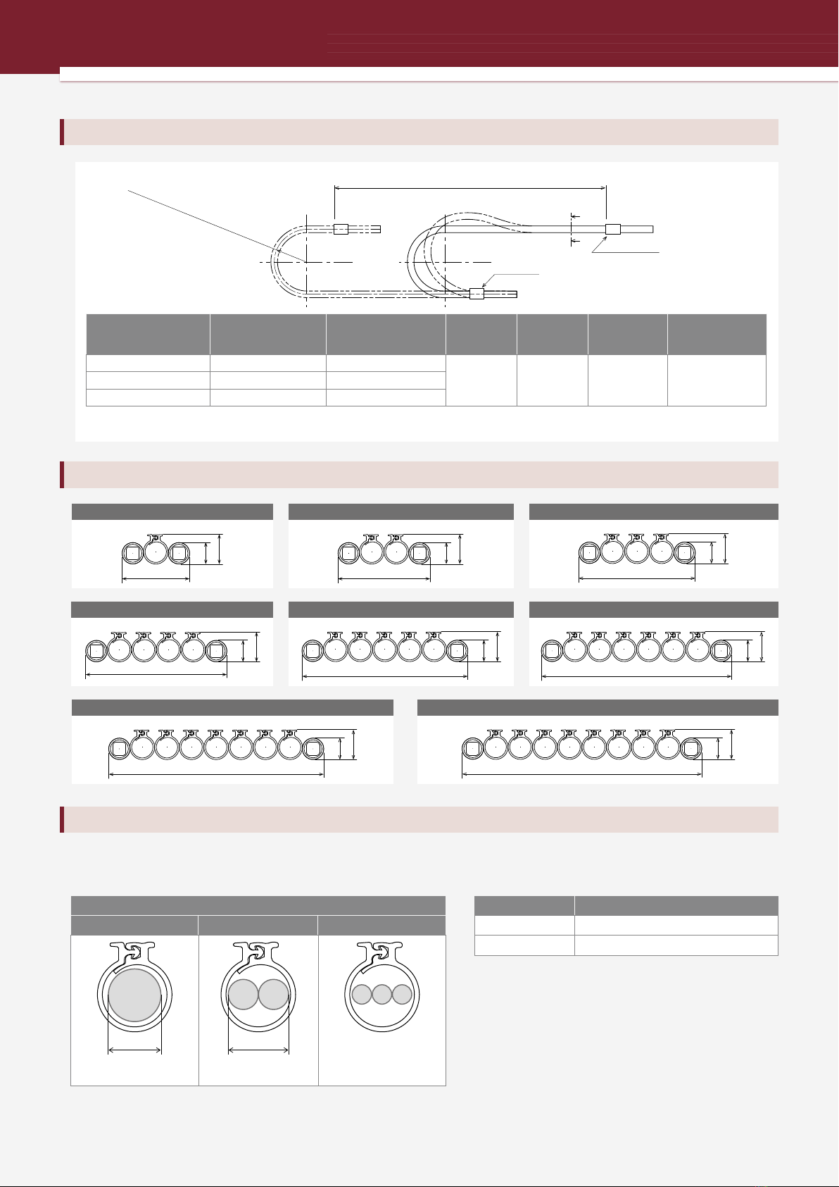
Check of installation dimensions
Step 4
Page
6
Item
Installation dimensions
Reference information
Check the space required for installation.
If the operating conditions exceed the load diagram, contact a Tsubaki representative.
Mounting height
223 to 243 mm
Required space (Width)
186 mm
Required space (Height)
323 to 343 mm
Example:
186 mm
223 to 243 mm
323 to 343 mm
Page
5
Item
Basic specifications
6 Fixing parts and installation dimensions
Reference information
Calculation of the number of support member links
Step 5
2
S
2
(H’ − 23) × π+ 2K+ 2CL +
P
Number of support member links =
Fixed end
Moving end
Travel length S
Clamp length CL
Leeway length K
Mounting height H’
Support member
bending radius R
R = 70/100/130
S
H’
K
P
CL
: Travel length (mm)
: Mounting height (mm)
:
Leeway length = 100 or more (mm)
:
Support member pitch (mm)
: Clamp length = 50 mm
(Recommended)
:
Fixed number for calculation
Determination of color
Step 6
Determine the color of the product.
Number of links
49 links
+
2
600
2
(233 − 23) × π
+ + (2 × 100) + (2 × 50) + 46
20
Number of support member links =
In case of S= 600, H’ = 233, support member bending radius R070
= 48.7933...
= 49
Example:
The formula is for the case when the
fixed end is at the center of the travel
length. After calculating, always round
up to a whole number.
Note:
Black White
9
Operating conditions:
Travel length: 0.6 m
Cable mass per meter: 0.195 kg/m
Unsupported length (m)
STravel length (m)
0.1
2
1
0.1
0 0.5 1 1.51.6
0.9
0.87
(kg/m)
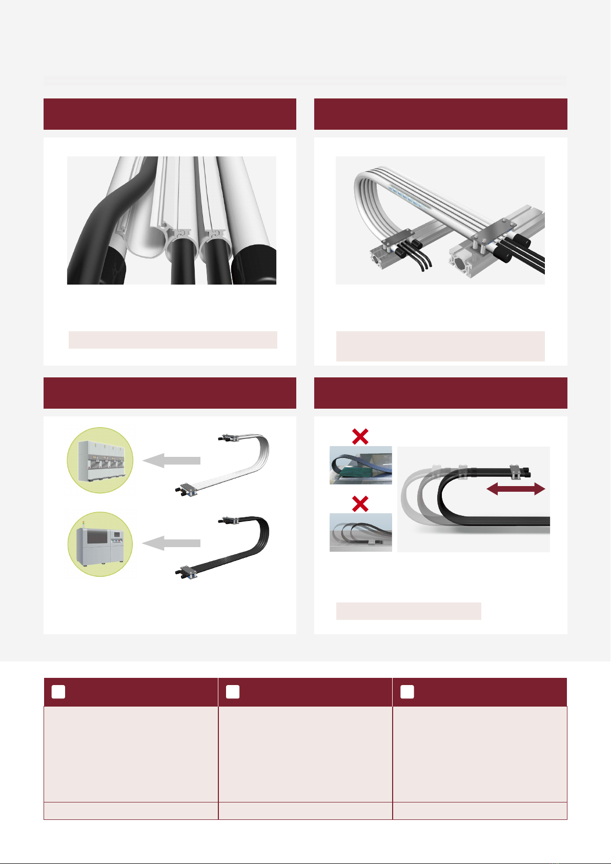
Check of capability with a load diagram
Step 3
Page
11 to 12
Item
Load Diagram
Reference information
Using the load diagram that shows the required number of openable tubes
and the support member bending radius, check that the operating conditions
(travel length, cable/tube mass) are within the capability range.
Example:
No.
(1)
(2)
(3)
Cable outer
diameter
mm
6.6
7.1
7.2
With/without
shield
Shielded
Shielded
Shielded
Quantity
1
1
1
0.052
0.070
0.073
Mass
kg/m
Installation cables
Support member bending radius
R070
Cable allowable bending radius = 7.2 × 8
= 57.6 mm
Select a support member
bending radius greater
than 57.6 mm.
No.
(1)
(2)
(3)
Cable outer
diameter
mm
6.6
7.1
7.2
With/without
shield
Shielded
Shielded
Shielded
Quantity
1
1
1
0.052
0.070
0.073
Mass
kg/m
Example:
Installation cables
Selection
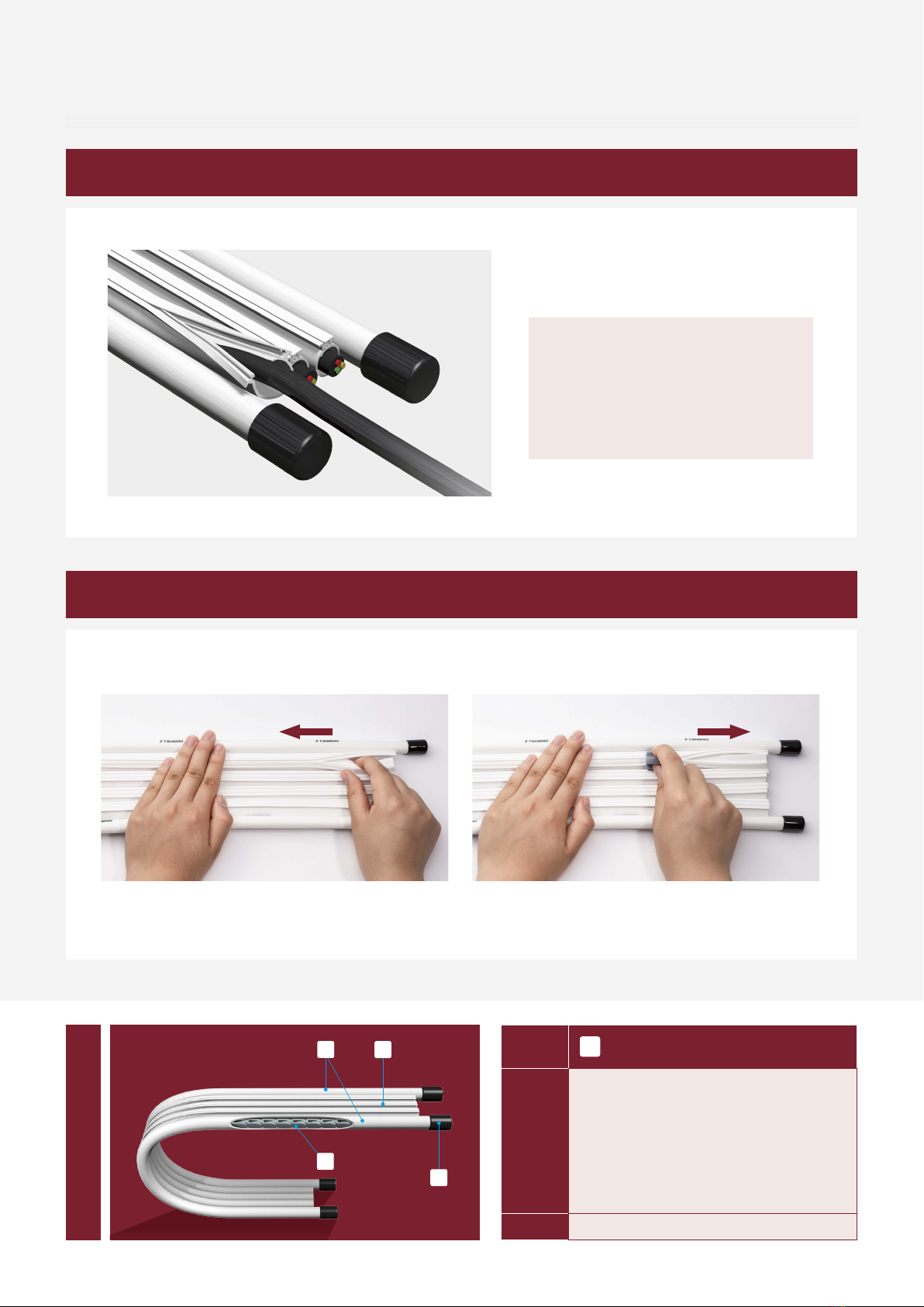
Determination of required number of openable tubes and required space (width) dimensions
Step 1
Page Item
Reference information
Determine the cable/tube arrangement and
required number of openable tubes. After they have
been determined, check the required space (width).
Required number of openable tubes
3
Required space (Width)
186 mm
Example:
5
6
Number of cables (jackets) and tubes to be installed and recommended materials
Installation dimensions
(3)(2) (1)
No.
(1)
(2)
(3)
Cable outer
diameter
mm
6.6
7.1
7.2
With/without
shield
Shielded
Shielded
Shielded
Quantity
1
1
1
0.052
0.070
0.073
Mass
kg/m
Installation cables
Determination of support member bending radius
Step 2
Page
5
Item
Basic specifications
Reference information
Determine the support member bending radius based on the allowable
bending radius of the cable/tube to be installed.
Check the allowable bending radius recommended by
the cable/tube manufacturer (for repeated bending).
Refer to the following guideline.
Cable with shield = Max. cable outer diameter × 8
Cable without shield = Max. cable outer diameter × 6
Tube = Max. tube outer diameter × 9
Select a support member bending radius
greater than the allowable bending radius of
the cable/tube.
Allowable bending radius of cable/tube
Determination of support member bending radius
Allowable bending
radius of cable/tube
Support member
bending radius
Cable/tube mass