Turbo Schematic LEVO SL User manual

TECHNICAL
GUIDE
TECHNICAL GUIDE
Schematic
TURBO LEVO SL
Electric Mountain Bike: Carbon frame

6.5.4. FORK ASSEMBLY ....................................................................................................................................................................................................................48
6.5.5. FRONT BRAKE ........................................................................................................................................................................................................................ 49
6.5.6. FRONT WHEEL........................................................................................................................................................................................................................ 50
6.5.7. HANDLEBAR...............................................................................................................................................................................................................................51
6.5.8. HANDLEBAR MOUNTING .......................................................................................................................................................................................................52
6.5.9. DROPPER POST ......................................................................................................................................................................................................................53
6.5.10. FINAL ADJUSTMENTS ..........................................................................................................................................................................................................54
7. CABLING DIAGRAMS ...................................................... 55
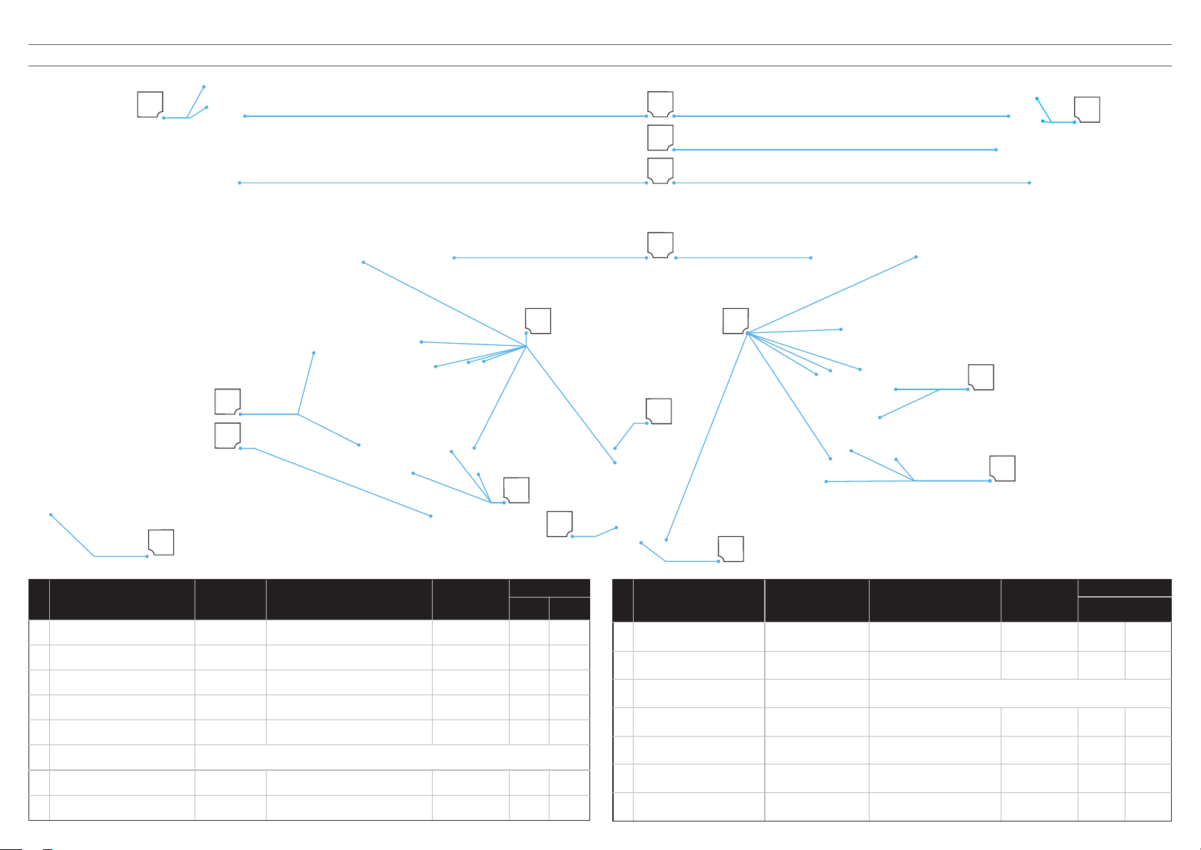
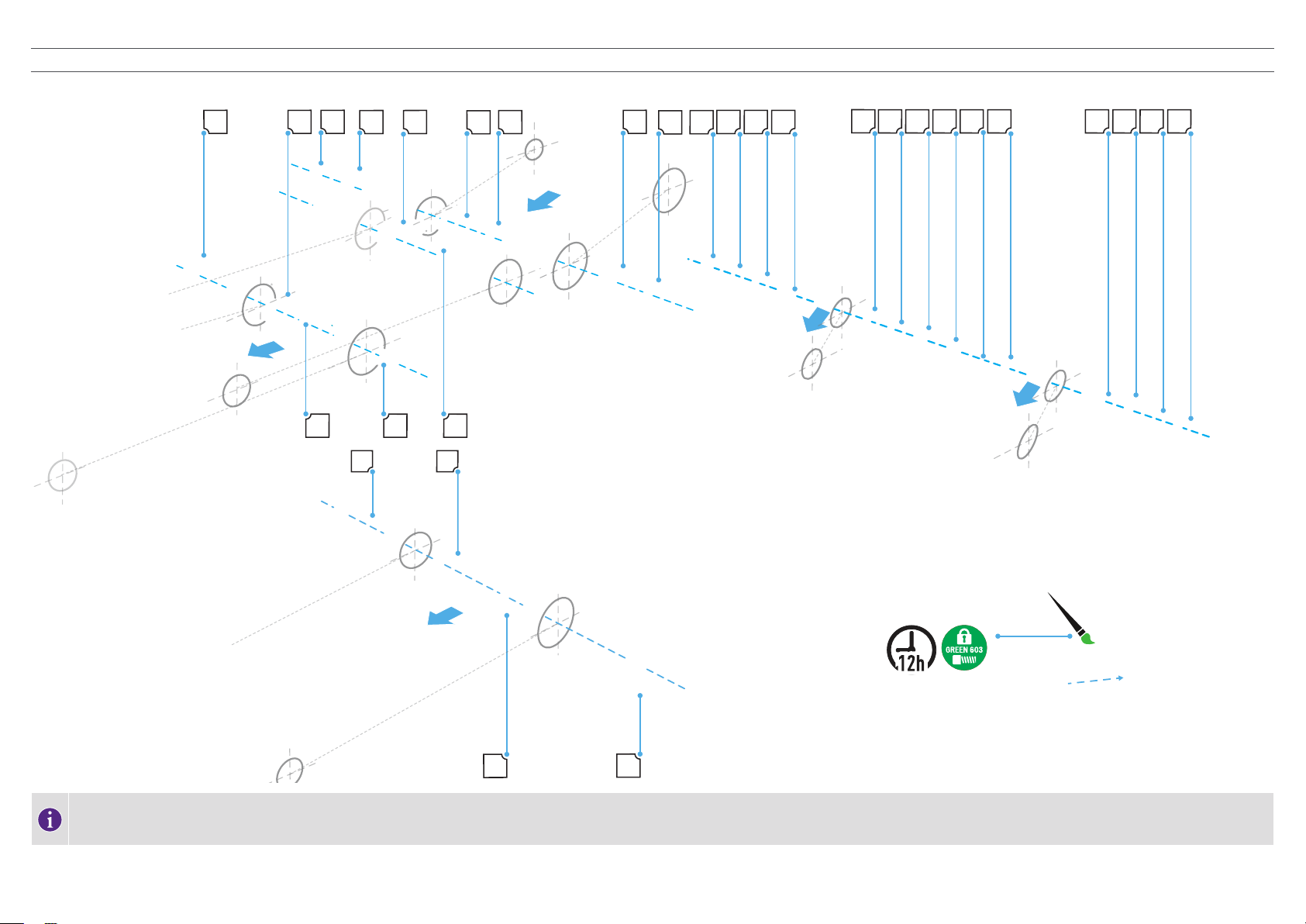
7.1. CABLE ROUTING .....................................................................................................................55
7.1.1. CARBON FRAME — NON AXS ..................................................................................................................................................................................................55
7.1.2. CARBON FRAME — AXS EQUIPPED ........................................................................................................................................................................................56
7.2. ELECTRICAL SCHEMATICS .................................................................................................... 57
7.2.1. SYSTEM SCHEMATICS — TCU ...............................................................................................................................................................................................57
7.2.2. SYSTEM SCHEMATICS — MASTERMIND TCU .....................................................................................................................................................................58
8. SERVICE PARTS ............................................................ 59
8.1. SERVICE PARTS: SHARED PARTS ..........................................................................................59
8.2. SERVICE PARTS: CARBON FRAME.........................................................................................60
INDEX
1. INTRODUCTION................................................................3
1.1. IMPORTANT............................................................................................................................... 3
1.2. WARNING SYMBOLS ................................................................................................................3
1.3. ASSEMBLY SETUP AND PREPARATION ....................................................................................4
2. FRAME GEOMETRY ..........................................................5
2.1. FRAME AS SOLD ......................................................................................................................5
3. TORQUE SPECIFICATIONS .................................................6
3.1. QUICK REFERENCE .................................................................................................................. 6
4. PIVOT BEARINGS AND SPACERS ......................................... 7
4.1. PIVOT BEARINGS AND SPACERS — EXPLODED VIEW ................................................................ 7
4.2. PIVOT BEARINGS AND SPACERS — SPECIFICATIONS ..............................................................8
5. PIVOT BOLTS ..................................................................9
5.1. PIVOT BOLTS — EXPLODED VIEW..............................................................................................9
5.2. PIVOT BOLTS — SPECIFICATIONS............................................................................................10
6. ASSEMBLY PROCESS ....................................................... 11
6.1. REAR TRIANGLE ASSEMBLY ................................................................................................... 11
6.1.1. SUSPENSION LINK BEARINGS ............................................................................................................................................................................................... 11
6.1.2. LINK AT SEAT TUBE ...................................................................................................................................................................................................................12
6.1.3. LINK AT SHOCK EXTENSION ....................................................................................................................................................................................................13
6.1.4. CHAINSTAY BEARINGS .............................................................................................................................................................................................................14
6.1.5. MAIN PIVOT ................................................................................................................................................................................................................................15
6.1.6. DOWN TUBE CHANNEL PLUG ................................................................................................................................................................................................ 16
6.1.7. HORST PIVOT — BEARINGS AND SPEED SENSOR ...............................................................................................................................................................17
6.1.8. LINK AT SEATSTAY PIVOT .........................................................................................................................................................................................................18
6.1.9. HORST PIVOT ............................................................................................................................................................................................................................ 19
6.1.10. MUD FLAP ............................................................................................................................................................................................................................... 20
6.1.11. DERAILLEUR HANGER .............................................................................................................................................................................................................21
6.1.12. DERAILLEUR ASSEMBLY .......................................................................................................................................................................................................22
6.1.13. REAR BRAKE CALIPER ...........................................................................................................................................................................................................23
6.2. REAR CABLES ......................................................................................................................24
6.2.1. REAR BRAKE HOSE .................................................................................................................................................................................................................24
6.2.2. DERAILLEUR CABLE ...............................................................................................................................................................................................................25
6.2.3. NON-DRIVE SIDE ICR PORT ...................................................................................................................................................................................................26
6.2.4. DROPPER CABLE ....................................................................................................................................................................................................................27
6.3. MOTOR AND BATTERY ASSEMBLY ........................................................................................28
6.3.1. MAIN HARNESS ........................................................................................................................................................................................................................28
6.3.2. DRIVE SIDE ICR PORT .............................................................................................................................................................................................................29
6.3.3. BATTERY .................................................................................................................................................................................................................................. 30
6.3.4. MOTOR PREPARATION ............................................................................................................................................................................................................31
6.3.5. MOTOR: STEP 1 ........................................................................................................................................................................................................................32
6.3.6. MOTOR: STEP 2 .......................................................................................................................................................................................................................33
6.3.7. MOTOR: STEP 3.........................................................................................................................................................................................................................34
6.3.8. ROCK GUARD ...........................................................................................................................................................................................................................35
6.3.9. TCU ASSEMBLY AND SYSTEM POWER UP..........................................................................................................................................................................36
6.3.10. MASTERMIND TCU ASSEMBLY AND SYSTEM POWER UP...............................................................................................................................................37
6.3.11. REAR SHOCK: CARBON SHOCK EXTENSION .....................................................................................................................................................................38
6.3.12. REAR SHOCK : ALLOY SHOCK EXTENSION ......................................................................................................................................................................39
6.3.13. SUSPENSION BOLTS............................................................................................................................................................................................................. 40
6.4. DRIVETRAIN ASSEMBLY ........................................................................................................41
6.4.1. REAR WHEEL ............................................................................................................................................................................................................................ 41
6.4.2. CHAIN GUIDE ............................................................................................................................................................................................................................42
6.4.3. SPIDER AND CHAINRING........................................................................................................................................................................................................43
6.4.4. CHAIN GUIDE ADJUSTMENT ................................................................................................................................................................................................. 44
6.5. FRONT END ..........................................................................................................................45
6.5.1. HEADSET....................................................................................................................................................................................................................................45
6.5.2. HEADSET CUPS ADJUSTMENT .............................................................................................................................................................................................46
6.5.3. FORK STEERER TUBE ............................................................................................................................................................................................................47

1. INTRODUCTION
1.1. IMPORTANT
THIS ASSEMBLY INSTRUCTION CONTAINS IMPORTANT INFORMATION. PLEASE READ CAREFULLY AND
STORE IN A SAFE PLACE.
This manual was drafted in English (original instructions) and may have been translated into other languages as applicable (translation of
original instructions).
This document is specific to your Turbo Levo SL bicycle and referred to in this manual as the Levo SL.
This manual should be read in addition to the Turbo Levo SL User Manual supplied with your bicycle, and the two documents should be kept
together for future reference. They contain important safety, performance, and technical information specific to your Levo SL, which you
should read before your first ride and keep for reference.
The Levo SL user manual is designed as a reference for a complete bicycle, including the Declaration of Conformity document at the back of
each language section. Since a frame up build requires the assembly of components (suspension fork, seat post, saddle, drivetrain assembly,
cockpit assembly, wheels), the information contained herein is intended to supplement the Levo SL User Manual in order to provide you with
the necessary information required to complete the assembly and eventually use your Levo SL. For assembly, only compatible and e-bike
approved components should be used. Please refer to a component manufacturers’ documentation for assembly instructions.
You should also read the entire Specialized Bicycle Owner’s Manual (“Owner’s Manual”) because it has additional important general
information and instructions which you should follow. If you do not have a copy of this document, you can download them at no cost at www.
specialized.com or obtain them from your nearest Authorized Specialized Retailer or Specialized Rider Care.
1.2. WARNING SYMBOLS
When reading this assembly instruction, note various important symbols and warnings explained below:
WARNING! The combination of this symbol and word indicates a potentially hazardous situation that, if
not avoided, could result in serious injury or death. Many of the Warnings say “you may lose control and
fall.” Because any fall can result in serious injury or even death, we do not always repeat the warning of
possible injury or death.
CAUTION: The combination of the safety alert symbol and the word CAUTION indicates a potentially
hazardous situation that, if not avoided, may result in minor or moderate injury, or is an alert against
unsafe practices.
The word CAUTION used without the safety alert symbol indicates a situation that, if not avoided, could
result in serious damage to the bicycle or the voiding of your warranty.
This symbol alerts the reader to information that is particularly important.
This symbol means that high quality grease should be applied as illustrated.
This symbol means that carbon assembly paste should be applied as illustrated to increase friction.
This symbol highlights the correct torque value for a specific bolt. In order to achieve the specified torque
value, a quality torque wrench must be used.
Tech tips are useful tips and tricks regarding installation and use.
We may occasionally issue updates and addenda to this document. Please periodically check
www.specialized.com or contact Rider Care to make sure you have the latest information.
Info: www.specialized.com
SPECIALIZED BICYCLE COMPONENTS
15130 Concord Circle, Morgan Hill, CA 95037 (408) 779-6229
0000193160_SC_R4, 4/23
A
1
LH
PART NUMBER
SYMBOLS LEGEND
ASSEMBLY PROCESS ORDER
INSERT PATH
ASSEMBLY DIRECTION
GREASE
BLUE THREAD LOCK
LEFT HAND THREAD
VIDEO GUIDE LINK
BOLT TORQUE REQUIRED

1.3. ASSEMBLY SETUP AND PREPARATION
This document guides you through the complete assembly of the 2023 Turbo Levo SL Carbon frame bicycles.
TURBO LEVO SL COMP CARBON
TURBO LEVO SL EXPERT CARBON
TURBO LEVO SL PRO CARBON
TURBO LEVO SL SW CARBON
TURBO LEVO SL SW CARBON FRMSET
TURBO LEVO SL SW LTD
TOOLS REQUIRED
Stable repair stand
Hex keys: 2.5 mm, 3 mm, 4 mm, 5 mm, 6 mm, 8 mm
Torx keys: T8, T10, T25, T30
Cable routing tools
Torque wrenches covering 0.8-50 Nm.
High-quality grease
High-quality carbon assembly paste
Loctite 603
Loctite 242
ASSEMBLY GUIDE VIDEOS
To access video content relating to the assembly process of the Turbo Levo SL Carbon, click on the links below to
go directly to the assembly video.
Use your smartphone camera to scan the QR codes on the opposite page.
You can also manually enter the web addresses below.
COMPLETE ASSEMBLY GUIDE VIDEO
https://vimeo.com/706376453/01fd3163c2
MOTOR AND BATTERY ASSEMBLY GUIDE VIDEO
https://vimeo.com/788453392/a945eb33bf
ASSEMBLY GUIDE VIDEOS QR CODE
Use your smartphone camera to scan the QR code to access the assembly instruction videos of the 2023
Turbo Levo SL Carbon.
Open the camera app on your phone.
Focus the camera on the QR code by gently tapping the code.
Follow the instructions on the screen to complete the action.
COMPLETE BUILD
ASSEMBLY GUIDE
SCAN ME
MOTOR AND BATTERY
ASSEMBLY GUIDE
SCAN ME
PREPARATION
The build starts with a bare 2023 Turbo Levo SL Carbon frame with no components assembled.
To build the Turbo Levo SL, it is essential to follow the order of operations as outlined in this guide.
Modifying the order of assembly will result in a longer build process.
Specific procedures are different for carbon and alloy frames. Follow the appropriate steps in the assembly guide
relating to your frame type.
Insert a standard 30.9 mm seatpost into the tube, then use a 4 mm hex bit to torque the seatpost clamp to 6.2
Nm / 55 in-lbf.
Place the bicycle frame into a stable repair stand.
WARNING: Do not clamp the carbon frame.

5
2. FRAME GEOMETRY
2.1. FRAME AS SOLD
A
B
C
D
N
F
G
H
I
J
K
E
L
M
O
ITEM S1 S2 S3 S4 S5 S6
A Stack (mm) 609 617 626 635 645 654
B Reach (mm) 405 425 445 470 495 525
C Head tube length (mm) 95 100 110 120 130 140
D Head tube angle (°) 64.5 °
E BB height (mm) 343 348 348 348 348 348
F BB drop (mm) -34 -29 -29 -29 -29 -29
G Trail (mm) 132
H Fork length (full) (mm) 560 570 570 570 570 570
ITEM S1 S2 S3 S4 S5 S6
I Fork rake/offset (mm) 44
J Front center (mm) 726 752 776 806 835 869
K Wheelbase (mm) 1158 1184 1208 1238 1267 1301
L Standover height (mm) 727 763 766 767 773 778
M Seat tube length (mm) 385 385 405 425 445 465
N Seat tube angle (°) 76
O Chainstay length (mm) 433 432 432 432 432 432
Crank length (mm) 165 165 170 170 170 175
ITEM S1 S2 S3 S4 S5 S6
Handlebar width (mm) 780
Stem length (mm) 40 50
Saddle width (mm) 155 143 143 143 143 143
Seatpost max insertion (mm) 180 180 200 220 240 260
Seatpost min. insertion (mm) 80
Top tube length (horizontal) (mm) 560 582 604 631 659 691
Fork size (mm) 144 150 150 150 150 150

6
# PART NAME TYPE BOLT SPEC TOOL
TORQUE
Nm in-lbf
1 TCU screw Screw M4 x 10 mm x 0.7 mm p T10 Torx 1 9
2 ICR bolt Screw M3 x 18 mm x 0.5 mm p T10 Torx 1 9
3 Water bottle cage bolt Bolt M5 x 18 mm x 0.5 mm p 3 mm hex 2.8 25
4 Battery mount bolts Bolt M6 x 14 mm x 1 mm p 4 mm hex 3 27
5 Rock guard bolt Bolt M6 x 14 mm x 1 mm p 4 mm hex 2.5 22
6 Rear suspension pivot bolts Refer to: PIVOT BOLTS-CARBON FRAME: SPECIFICATIONS in this manual
7 Rear thru-axle Thru-axle M12 x 148 mm x 0.5 mm p 6 mm hex 15 133
8 Derailleur hanger Bolt As supplied 8 mm hex 25 220
# PART NAME TYPE BOLT SPEC TOOL
TORQUE
Nm in-lbf
9 Non-drive side motor bolts Bolt M10 x 25 mm x 1 mm p 5 mm hex 10 90
10 Drive side motor bolts Bolt M6 x 21 mm x 1 mm p 5 mm hex 13 115
11 Front fork thru-axle Thru-axle Refer to fork manufacturer
12 Seat collar Bolt M5 x 18 mm x 1 mm p 4mm hex 6.2 55
13 Stem at steerer tube Bolt M6 x 20 mm x 1 mm p 5 mm hex 8 71
14 Stem at handlebar Bolt M6 x 20 mm x 1 mm p 5 mm hex 6 53
15 Speed sensor bolt Bolt M4 x 14 mm x 0.7 mm p 3 mm hex 3 26
3. TORQUE SPECIFICATIONS
3.1. QUICK REFERENCE
1
3
10
2
12
13
15
4
14
5
66
9
8
11
7
14

7
4. PIVOT BEARINGS AND SPACERS
4.1. PIVOT BEARINGS AND SPACERS — EXPLODED VIEW
HA
A H
BB
B
B
PQ R Q S S Q Q PR
M
M
M
D
EEC J M
C DJ
Apply green Loctite 603 retaining compound to the bearing bore interface surfaces, then press all the bearings into their respective pivot locations. After installing the bearings, allow the Loctite 603 retaining compound to cure
12 hours before riding the bicycle.

8
# PIVOT
SERVICE PART
NUMBER QTY MATERIAL
Ø OD (mm)
Ø ID (mm) WIDTH (mm) THREAD (mm) LENGTH (mm) TOOL
BEARING
NUMBER
AMain pivot bearing
S210600003
2 Steel 24 12 6 N/A N/A N/A 6901-2RS
BHorst link bearing 4
Steel 21 12 5 N/A N/A N/A 6801-2RS
CLink at seat tube 2
DLink at extension 2
ELink at seatstay 2
HMain pivot inner spacer
S210500019
2 Aluminum 19.5 12.1 3 N/A N/A N/A N/A
JLink at seat tube inner spacer 2 Aluminum 19.5 12.1 3 N/A N/A N/A N/A
MLink at seatstay spacers 4 Aluminum 19.5 12.1 3 N/A N/A N/A N/A
PHorst link outer flip chip 2 Aluminum N/A N/A N/A N/A N/A N/A N/A
Q Horst link outer spacer 4 Aluminum 21 12 2.5 N/A N/A N/A N/A
RHorst link inner spacer 2 Aluminum 16 616 N/A N/A N/A N/A
SHorst link inner flip chip 2 Aluminum N/A N/A N/A N/A N/A N/A N/A
4.2. PIVOT BEARINGS AND SPACERS — SPECIFICATIONS

9
5. PIVOT BOLTS
5.1. PIVOT BOLTS — EXPLODED VIEW
O
OIK
I GF
LL U TK
All pivot bolts are factory treated with a threadlocker patch on the threads. If it begins to wear off, remove
any remaining threadlocker, then apply a new coat of Loctite 243 or install new bolts with the pre-applied
threadlocker patch.
CAUTION: Only apply grease to the unthreaded portion of the bolt shaft and the inner bolt head surface
(YELLOW highlighted portion of bolts as shown in the image).
CAUTION: Contaminating the threads of any of the pivot bolts with grease could lead to the Loctite not
functioning as intended; the bolts could come loose causing damage to the bicycle.
For best alignment results, do not torque any of the rear triangle pivot and shock bolts until the rear triangle is
fully assembled to the front triangle.

10
5.2. PIVOT BOLTS — SPECIFICATIONS
# PIVOT SERVICE PART NUMBER QTY MATERIAL
Ø OD (mm)
Ø ID (mm) WIDTH (mm) BOLT SIZE LENGTH (mm) TOOL
TORQUE
Nm in-lbf
FMain pivot bolt DS
S210500019
1 Aluminum N/A N/A N/A M12 left hand 20 6 mm hex 24 210
GMain pivot bolt NDS 1 Aluminum N/A N/A N/A M12 20 6 mm hex 24 210
ILink at seat tube bolt 2 Aluminum N/A N/A N/A M12 17 6 mm hex 20 180
KLink at extension bolt 2 Aluminum N/A N/A N/A M12 14 6 mm hex 24 210
LLink at seatstay bolt 2 Aluminum N/A N/A N/A M12 27 6 mm hex 20 180
OHorst link (dropout) pivot bolt 2 Coated steel N/A N/A N/A M6 32 5 mm hex 10 90
TForward shock mounting bolt 1 Stainless steel N/A N/A N/A M5 13 4 mm hex 5.5 49
URear shock mounting bolt 1 Stainless steel N/A N/A N/A M8 28 6 mm hex 20 180

11
6. ASSEMBLY PROCESS
6.1. REAR TRIANGLE ASSEMBLY
DD DD EEEE
C
C
A
A
C
C
6.1.1. SUSPENSION LINK BEARINGS
# PART NAME SERVICE PART NUMBER - CARBON SERVICE PART NUMBER - ALLOY QTY SPEC / DESCRIPTION TOOL TORQUE
Nm in-lbf
A Shock link — Carbon
S214300007
1 LINK,MTB,PA TRAIL FSR G1,29F/27.5R,ALY N/A N/A N/A
C Link forward bore bearing 2
6801-2rs
N/A N/A N/A
D Link mid bore bearing 2 N/A N/A N/A
E Link rear bore bearing 2 N/A N/A N/A
Apply green Loctite 603 to all the bearing/bore interface surfaces 12 hours before pressing all the bearings
into their respective pivot locations.
CAUTION: When installing the mid bore bearings, using a bearing press tool with a bearing kit adaptor is
critical.
Press the link at seat tube bearings (C) into the front bore of the link, and the link at seatstay bearings (E) into the
rear bore from the outside of the link.
Press the link at extension bearings (D) from the inside of the link.
Install the link at extension bearings (D) using a bearing press tool with the correct bearing kit adaptor.

12
I
I
I
I
J
J
J
J
A
A
6.1.2. LINK AT SEAT TUBE
# PART NAME SERVICE PART NUMBER —
CARBON
SERVICE PART NUMBER —
ALLOY QTY SPEC / DESCRIPTION TOOL TORQUE
Nm in-lbf
A Link S214300007 1 LINK,MTB,PA TRAIL FSR G1,29F/27.5R,ALY N/A N/A N/A
I Link at seat tube pivot bolt Part of suspension bolt kit.
S210500019
Part of suspension bolt kit.
S220500016
2 M12 x 17 mm x 1.0 mm p, bolt 6 mm hex 20 180
J Link at seat tube pivot — spacer 2 12.1 mm id x 19.5 mm od x 3 thick, spacer N/A N/A N/A
For best alignment results, do not torque any of the rear triangle pivot and shock bolts until the rear triangle is
fully assembled to the front triangle.
Grease, then place the link at seat tube inner spacers (J) against the link at seat tube bearings (C) (reduced edge
facing toward the bearing).
Align the bearings and spacers of the link with the bore in the seat tube.
Grease the non-threaded surfaces, then thread the link at seat tube bolts (I) into the frame.
Use a 6 mm hex bit and hand tighten the two bolts.

13
K
A
K
6.1.3. LINK AT SHOCK EXTENSION
# PART NAME SERVICE PART NUMBER QTY SPEC / DESCRIPTION TOOL TORQUE
Nm in-lbf
A Shock extension — Carbon S216300005 1 LINK,MTB,PA TRAIL FSR G1,29F/27.5R,ALY N/A N/A N/A
K Link at extension bolt Part of suspension bolt kit.
S210500019 2 M12 x 14 mm x 1 mm p, bolt 6 mm hex 24 210
Place a cloth over the frame to prevent the extension arm from damaging the paint.
Do not assemble the rear shock until the motor and battery assemblies are complete.
Place the extension arm around the seat tube and align the extension arm bores with the link mid bores.
Grease the non-threaded surfaces, then thread the link at extension bolts (K) into the link mid bores.
Use a 6 mm hex key to hand tighten the two bolts.

14
AA
D E
B C
1
2
3
6.1.4. CHAINSTAY BEARINGS
SPEED SENSOR
REAR BRAKE GUIDE TUBE
DERAILLEUR GUIDE TUBE
# PART NAME SERVICE PART
NUMBER QTY SPEC / DESCRIPTION TOOL TORQUE
Nm in-lbf
A Main pivot bearings — Carbon Part of suspension bearing
kit. S210600003 2 12 mm id x 24 mm od x 6 mm w, bearing N/A N/A N/A
B Chainstay — Carbon (satin) S211500005 1 CHS MY22 LEVO SL CRBN, STN CRBN N/A N/A N/A
B Chainstay — Carbon (gloss) S211500008 1 CHS MY22 LEVO SL CARBON, CARBON, GLS SMK N/A N/A N/A
C Speed sensor cable S196800019 1 ELE MY20 MTB SL SYSTEM, SPEED SENSOR KIT N/A N/A N/A
D Derailleur cable guide tube 1 TUBE,ICR,5.5 X 7,NYLON,BLK - Cut length: 490 mm N/A N/A N/A
E Rear brake hose guide tube 1 TUBE,ICR,5.5 X 7,NYLON,BLK - Cut length: 410 mm N/A N/A N/A
1. Thread the speed sensor cable from the main pivot end of the chainstay through the lower hole on the non-drive
side until it exits the chainstay behind the horst pivot. When assembling the rear triangle to the front triangle,
thread the speed sensor cable through the motor area and connect the speed sensor into the port on the motor.
2. On each side, press the main pivot bearings (A) into the main pivot bores from the inside of the chainstays.
3. Insert the derailleur guide tube (D) through the ICR port located in the drive side of the chainstay and route it to
the rear port of the chainstay. Insert the brake guide tube (E) through the inner ICR port located in the non-drive
side of the chainstay and route it to the mid port of the chainstay.
Apply green Loctite 603 to all the bearing/bore interface surfaces 12 hours before pressing all the bearings
into their respective pivot locations.

15
F
G
H
H
LH
6.1.5. MAIN PIVOT
# PART NAME SERVICE PART NUMBER QTY SPEC / DESCRIPTION TOOL TORQUE
Nm in-lbf
F Main pivot bolt DS
Part of suspension bolt kit.
S210500019
1 M12 x 20 mm x 1 mm p, left hand, bolt 6 mm hex 24 210
G Main pivot bolt NDS 1 M12 x 20 mm x 1 mm p, bolt 6 mm hex 24 210
H Main pivot inner spacer 2 12.1 mm id x 19.5 mm od x 3 mm w, spacer N/A N/A N/A
The drive side main pivot bolt is a left-hand thread.
Carefully guide the two nylon cable guide tubes and the speed sensor cable plug through the two cable slots at the
back of the frame and align the forward bore of the chainstay with the main pivot on the frame.
Grease then place the main pivot inner spacers (H) against the inside main pivot bearings (H) (reduced edge
facing toward the bearing).
Grease the non-threaded surfaces, then insert the main pivot drive side bolt (F) and the main pivot non-drive side
bolt (G). Use a 6 mm hex key, to hand tighten only.

16
A
30
sec
<
12
3
6.1.6. DOWN TUBE CHANNEL PLUG
REAR BRAKE GUIDE TUBE
DERAILLEUR GUIDE TUBE
# PART NAME SERVICE PART NUMBER QTY SPEC / DESCRIPTION
ADown tube channel plug S226500009 1 ICR,CABLE GUIDE,MTB,PA TRAIL FSR G1,29F/27.5R
1: Place a small amount of Loctite 416 at the end of the rear brake guide tube. Briefly allow the glue to spread around the guide tube.
2. Quickly insert the guide tube as far as possible into the base of the down tube channel plug (A) and hold in place allowing the glue to set.
Repeat the process with the rear derailleur guide tube.
3. Insert the channel plug into the cable guide tube that runs down the inside of the down tube.
Loctite 416 has a 20-30 second work time.
Ensure the down tube channel plug is completely inserted into the guide tube. Failure to do so could cause the
battery to snag.

17
BBRRBBBBBB RR
1
2
6.1.7. HORST PIVOT — BEARINGS AND SPEED SENSOR
SPEED SENSOR BOLT
SPEED SENSOR MAGNET
SPEED SENSOR MAGNET BOLTS
SPEED SENSOR
SPEED SENSOR GROMMET
From the inside of each Horst pivot bore, insert a bearing (B).
Insert the center spacers (R) from the outside of the Horst pivot bores.
On the outside of each Horst pivot bore, insert a bearing (B) sandwiching the center spacer between the other
bearing.
Apply green Loctite 603 to all the bearing/bore interface surfaces 12 hours before pressing all the bearings
into their respective pivot locations.
The speed sensor must be installed before assembling the Horst pivot.
Align the chainstay close to the Horst link pivot.
Insert the speed sensor into the hole at the front of the dropout, then feed it through the chainstay until is passes
the bolt hole.
Insert the speed sensor bolt into the hole. Use a torque wrench and 3 mm hex bit to torque the bolt to
specification.
Pry open the grommet and place it over the speed sensor cable behind the sensor.
Slide the rubber grommet up into the speed sensor hole to secure it.
When assembling the rear brake disc, the speed sensor magnet must be installed on the rotor. Four of the six bolts
are standard rotor bolts. The remaining two bolts (M5 x 0.8 pitch x 15 mm length with a countersunk flat head)
attach the speed sensor magnet to the rotor.
# PART NAME SERVICE PART NUMBER QTY SPEC / DESCRIPTION TOOL TORQUE
Nm in-lbf
R Horst link inner spacer Part of suspension bolt kit.
S220500016
2 6 mm id x 16 mm od x 16 mm w, stepped spacer N/A N/A N/A
B Horst link bearing 4 12 mm id x 21 mm od x 5 mm w, ball bearing N/A N/A N/A
Speed sensor kit
S196800019
1 ELE MY20 MTB SL SYSTEM, SPEEDSENSOR KIT N/A N/A N/A
Speed sensor cable 1CA,SNSR,SPEED,BROSE, AMPHENOL, WERNERWIRTH COPY CON,650MM N/A N/A N/A
Speed sensor bolt 1 M4 x 18 mm x 0.7 mm p, bolt 3 mm hex 1 9
Speed sensor grommet S216800021 1 ELE TURBO MTB SPEED SENSOR GROMMET N/A N/A N/A
6-Bolt rotor mount speed sensor magnet
assembly S194200016
1 6-BOLT VERSION N/A N/A N/A
Speed sensor magnet bolts 2 M5 x 16 mm x 0.8 mm p, bolt T25 Torx 6.2 56

18
LLLL MMMMMMMM
6.1.8. LINK AT SEATSTAY PIVOT
Grease and place the link at seatstay spacers (M) (x4) with the reduced edge against the bearings of the upper
link rear bore.
Rotate the seatstay into position to align the seatstay bore with the link pivot bore.
Grease the non-threaded surfaces, then insert the seatstay bolts (L) (x2) through the seatstay and link.
Use a 6 mm hex key to hand tighten the two bolts.
# PART NAME SERVICE PART NUMBER QTY SPEC / DESCRIPTION TOOL TORQUE
Nm in-lbf
Seatstay S215000005 1 SS, MTB, PA TRAIL FSR G1, 29F/27.5R, CRBN N/A N/A N/A
L Link at seatstay bolt Part of Carbon suspension bolt kit.
S210500019
2 M12 x 27 mm x 1.0 mm p, bolt 6 mm hex 20 180
M Link at seatstay spacers 4 12.1 mm id x 19.5 mm od x 3 mm w, spacer N/A N/A N/A

19
OOQQQQSSQQQQPP A PPOO SS
6.1.9. HORST PIVOT
FLIP CHIP - 27.5 “REAR WHEEL (DEFAULT)
FLIP CHIP - 29" REAR WHEEL
CAUTION: Before installing a 29"rear wheel on a S1 or S2 size frame, consult section 6. GENERAL NOTES
ABOUT ASSEMBLY in the Levo SL User Manual regarding saddle clearance.
WARNING: The drive side and non-drive side Horst flip chips must both be aligned in the same 27.5" or
29" position. Improperly installed flip chips can damage the frame and can also cause you to lose control
and fall.
Always assemble the chainstay protector before assembling the horst pivot flip chips and bolts
Once the flip chips are installed and torqued, there will be a small gap between the outer flange and the
chainstay. Do not over tighten
Clean the chainstay, then attach the chainstay protector (A) to the drive side chainstay with the protector over the
flip chip pivot hole.
# PART NAME SERVICE PART NUMBER QTY SPEC / DESCRIPTION TOOL TORQUE
Nm in-lbf
A Chainstay protector S216900005 1 CS PROTECTOR,MTB,PA TRAIL FSR G1.1 N/A N/A N/A
O Horst pivot bolt
S214200059
2 M6 x 32.5 mm 1 mm p, bolt 5 mm hex 10 90
P Horst link outer flip chip 2 DO PIVOT SPACER,GEO ADJ,6.0 ID, FLIP CHIP N/A N/A N/A
Q Horst link outer spacer 4 12 mm id x 21 mm od x 2.5 mm w, spacer N/A N/A N/A
S Horst link inner flip chip 4 DO PIVOT SPACER,GEO ADJ 6 MM X 1 MM, FLIP CHIP N/A N/A N/A
Grease the spacers (Q) (x4) and place the reduced surface side against the bearings (B).
Rotate and align the seatstay pivot with the chainstay pivot while pulling the excess speed sensor cable from the
motor area.
NOTE: Ensure the speed sensor cable is free from the Horst pivot and cannot get pinched which would damage
the cable.
Depending on the size of your rear wheel, align the flip chip inner (S) and outer spacers (P) in either the 27.5"or
29" position and place them against the frame.
Ensure that the inner and outer flip chip spacers are aligned in the same direction.
Make sure all flip chips are fully seated and aligned with the chainstay protector before inserting the bolt.
Grease all non-threaded surfaces and install the Horst link pivot bolts (O). Use a 5 mm hex key to hand tighten
only.

20
A B
6.1.10. MUD FLAP
This assembly keeps mud and debris from collecting in the gap between the main frame and chainstay.
Apply Loctite to the two mud flap bolts and place them in the two holes in the mud flap.
Place the mud flap on the back of the frame on top of the chainstay.
Flex the mud flap up to access the two mounting holes in the frame.
Use a 2.5 mm hex key to tighten the two mud flap bolts.
# PART NAME SERVICE PART NUMBER QTY SPEC / DESCRIPTION TOOL TORQUE
Nm in-lbf
A Mud flap kit
S214200057
1 KIT,MUD FLAP,MTB,PA TRAIL FSR G1 N/A N/A N/A
B Mud flap bolt 2 M4 x 12 mm x 0,7 mm p, bolt 2.5 mm hex 0.3 2.7
Table of contents
Other Turbo Bicycle manuals