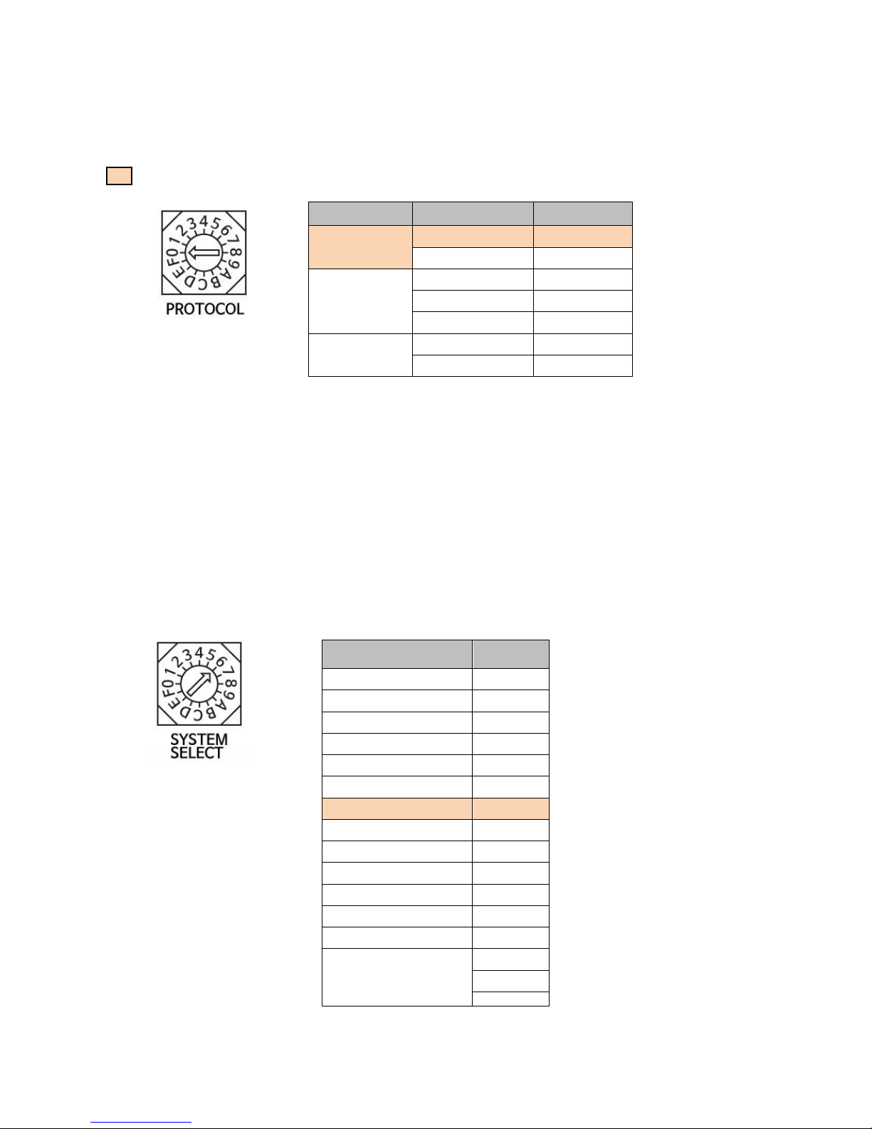
TV Logic TVC-FA301N User manual

7
TVC-FA301N
Installation Manual
Ver 1.15

2
Camera Setup
①CAMERA ADDRESS [ID] SETUP
Change the Camera ID as shown below.
- Up to 15 addresses can be set to control multiple cameras.
※ Do not use number 0.
- Factory default is set to 1.
- When operating multiple cameras with the controller, set the different ID for
each camera.
* It is recommended to use a micro driver to make changes.
②
③
④
Output
Power
Communication Type
①

3
②PROTOCOL SETUP
Change the communication protocol as shown below.
: Factory Default
- Set the protocol correspond to the controller.
- Be sure to change the protocol while the power is off.
③SYSTEM SELECT SETUP - VIDEO FORMAT
Set the video output format by changing the switch as shown below.
- Make sure to change the format while the power is off.
- HDMI, HD-SDI, DVI-I, CVBS(SD) simultaneous output.
※For the stable use of camera, we recommend selecting P series for CVBS.
Protocol
BAUD RATE
Switch
VISCA
9600 bps
0
38400 bps
1
PELCO-D
2400 bps
2
9600 bps
3
38400 bps
4
PELCO-P
4800 bps
5
9600 bps
6
Output video format
Switch
1920x1080p60
0
1920x1080i60
1
1920x1080p30
2
1280x720p60
3
1280x720p30
4
1920x1080p59.94
5
1920x1080i59.94
6
1280x720p59.94
7
1920x1080p50
8
1920x1080i50
9
1920x 1080p25
A
1280x720p50
B
1280x 720p25
C
Reserved
D
E
F

4
④COMMUNICATION SETUP
(OFF: ↑/ ON:↓)
Select RS-422 or RS-232C by using ON/OFF DIP switch no.1 and
2.
COMMUNICATION
1
2
RS-422
OFF
OFF
RS-232C
ON
OFF
MEMO

5
Bracket Installation
Fix the bracket to the bottom of the camera with screws (4EA).
Ceiling type
Wall mount type
Fix the camera into the ceiling bracket.
Fix the camera into the wall mount bracket.
Fix the camera using the 4 screws on both sides of the bracket.
Loosen slightly
a hexagon
screw and use.
it

6
CAMERA CONNECTION
●RS-232C VISCA Connector (MINI DIN 8PIN, FEMALE)
PIN NO.
VISCA IN
VISCA OUT
1
DTR IN
DTR OUT
2
DSR IN
DSR OUT
3
TXD IN
TXD OUT
4
GND
GND
5
RXD IN
RXD OUT
6
GND
GND
7
NOT CONNECTED
NOT CONNECTED
8
NOT CONNECTED
NOT CONNECTED
SAMPLE
TVR-200H

7
●RS-422 CONNECTOR
PIN NO.
RS-422
1
TXD IN+
2
TXD IN-
3
RXD IN+
4
RXD IN-
5
GND
6
TXD OUT+
7
TXD OUT-
8
RXD OUT+
9
RXD OUT-
SAMPLE
TVR-200H

8
RJ-45 CONNECTOR
PIN NO.
RJ-45
1
RXD OUT+
2
RXD OUT-
3
TXD OUT+
4
RXD IN+
5
RXD IN-
6
TXD OUT-
7
TXD IN+
8
TXD IN-
SAMPLE

9
RS-422 CONNECTION (TVR-200H)
TVC-FA301N RS-422 Connection
1. Check : a) Camera Firmware Ver. : 2.00 or higher b) Additional Camera Type (end with B)
2. DIP switch no.5 has to be set to ON. (on the bottom of the camera)
3. Connection method is shown in the diagram below.
* 422 Connection with 9PIN connector from TVR-200H controller.

10
422 connection wtih RJ-45 connector from TVR-200H controller.
1. Check : a) Camera Mech Firmware Ver. 2.00 or higher b) Additional Camera Type B
2. DIP switch no.5 has to be set to ON. (on the bottom of the camera)
3. Connection method is shown in the diagram below.

11
422 connection of 4 cameras with RJ-45 connector from TVR-200H controller.
See page 11 for more detail.

12
RJ-45 Connector ⇦⇨ 9P Connector connection diagram.
11Page 케이블 제작을 참고하세요.
MEMO

13
TVC-FA301N camera & TVR-200H setup check
1. Set each camera's ID and Protocol 0 (ex: VISCA, 9600) and set the Communication 1 dip switch up.
2. Setup and connecting of TVR-200H
Press and hold the MENU button on the bottom of the LCD screen to set the Baudrate and Interface
values using the joystick. Press the EXIT button to exit the setting.
Press and hold
①Protocol : VISCA check
②Baudrate : 9600 check and modify
③Interface : RS-422 check and modify
④EXIT : Exit the setting

14
RS-232C Connection
Use the RS-232C / LAN gender supplied with the camera, and set the communication speed to
9600bps.
Refer to page 15 for more information.
1. Set the camera ID, protocol and communication as shown below.
●RS-232C Connection between TVC-FA301N and TVR-200H
Press and hold the MENU button on the bottom of the LCD screen to select Baudrate 9600, Interface
RS-232C using the joystick. Press the EXIT button to exit the setting.

15
See page 15 for more detail.

16
1. 232C-LAN cable connection diagram between the cameras.
(* It differs from normal network cable formation)
* If you only want to connect the camera using the network direct line, use the optional KTM-100.
1) Configuration of camera and camera control line using 2 LAN cables
2) Using 1 LAN cable divided into 4 lines for camera and control line.

17
2. KTM-100 (Optional Product)
Main purpose of this product is to quickly respond to control lines and camera problems.
If you installed the camera, display, and control lines into the control room, using KTM-100 would
make the connection easier.
For RS-232C connection, with supplied LAN gender, up to 7 cameras can be installed in a simple way
by connecting KTM-100 to the camera using "Direct" LAN cable. Also, enables you to check the
communication status by the LED light on the LAN connector port when power is supplied to KTM-100.
Use the Direct LAN cable for the
connection b/w KTM-100 and
Cameras.
Refer to Page 15 for more
information.

18
Installation Check
1. Before applying power, make sure that there is no abnormality in wiring.
2. Make sure to change the camera and controller settings (protocol and video output format, etc.)
while the power is off.
3. Check that the communication between the camera and the controller (RS-232C, RS422) match.
4. Match the protocols and transmission speed of the camera and controller.
Operation Check
Enter the camera menu(OSD) to confirm or change the setting.
◈To confirm the current camera ID, protocol, resolution and other camera information
Go to <System Info.> menu.
◈The picture is reversed when the camera is put upside down.
Go to <Image> menu and turn on the Image Flip function.
◈When the camera is mounted upside down, it moves in the opposite direction to the controller.
1) Press and hold the [MENU] button of the TVR-200H.
2) Go to <Motion/Action> menu and select <Motion> menu to invert the PT Direction(Pan Dir).
◈Unnecessary characters continually appear on the screen?
Go to <Display> menu and turn off the PTZ Information, Flip status, Action Title, Preset Label and IR Info..
Or turn off the Display All.
◈The basic movement of the PTZ camera is much faster than what is used to be.
Go to <Motion/Action> menu and select <Motion> menu to slow down the PT Max Speed.
◈Want to be able to distinguish the background and the subject more smoothly than the existing
PTZ camera?
1) Go to <Picture> menu to turn off the HR Mode.
2) Go to <Image>menu and decrease the Aperture value.
◈Want to factory reset everything in the camera?
Go to <System Info.> menu and then <Additional Info.> menu. Select <System Initialize> menu to activate
the Factory Default function.
Refer to Page 15 for more
information.

19
MEMO

20
FOR MORE INFORMATION PLEASE VISIT : http://www.tvlogic.tv
12F, ACE HIGH-END 8, 84 Gasan digital 1-ro, Geumcheon-gu, Seoul, 153-802, KOREA
Other manuals for TVC-FA301N
1
Table of contents
Other TV Logic Security Camera manuals