Tyco Fire Protection Products RAPID RESPONSE LFII Series User manual

RAPID RESPONSE Series LFII Residential Sprinklers
4.9 K-factor Flat-Plate Concealed Pendent
Wet Pipe and Dry Pipe Systems
Page 1 of 6 FEBRUARY 2014 TFP443
IMPORTANT
Always refer to Technical Data
Sheet TFP700 for the “INSTALLER
WARNING” that provides cautions
with respect to handling and instal-
lation of sprinkler systems and com-
ponents. Improper handling and in-
stallation can permanently damage
a sprinkler system or its compo-
nents and cause the sprinkler to fail
to operate in a fire situation or cause
it to operate prematurely.
General
Description
The TYCO RAPID RESPONSE
Series
LFII Residential Flat-Plate Concealed
Pendent Sprinklers (TY2524) are decora-
tive, fast response, fusible solder sprin-
klers designed for use in residential oc-
cupancies such as homes, apartments,
dormitories, and hotels.
The Cover Plate/Retainer Assembly con-
ceals the sprinkler operating compo-
nents above the ceiling. The at prole
of the Cover Plate provides the optimum
aesthetically appealing sprinkler design.
Additionally, the concealed design of the
Series LFII Residential Flat-Plate Con-
cealed Pendent Sprinklers provides 1/2
inch (12,7 mm) vertical adjustment. This
adjustment provides a measure of ex-
ibility when cutting xed sprinkler drops.
The Series LFII Residential Flat-Plate
Concealed Pendent Sprinklers are in-
tended for use in the following systems:
•wet and dry pipe residential sprin-
kler systems for one- and two-fam-
ily dwellings and mobile homes per
NFPA 13D
•wet and dry pipe residential sprin-
kler systems for residential occu-
pancies up to and including four sto-
ries in height per NFPA 13R
•wet and dry pipe sprinkler systems
for the residential portions of any
occupancy per NFPA 13
The Series LFII Residential Sprinklers
have been designed with heat sensitiv-
ity and water distribution characteristics
proven to help in the control of residen-
tial res and to improve the chance for
occupants to escape or be evacuated.
The Series LFII Residential Flat-Plate
Concealed Pendent Sprinklers are
shipped with a Disposable Protective
Cap. The Protective Cap protects the
sprinkler during ceiling installation or
nish. After ceiling installation is com-
plete, the Protective Cap is removed
and the Cover Plate/Retainer Assem-
bly is installed. Removing the Protec-
tive Cap is required for proper sprinkler
performance.
Dry Pipe System Application
The Series LFII Residential Flat-Plate
Concealed Pendent Sprinkler offers a
laboratory approved option for design-
ing dry pipe residential sprinkler sys-
tems, whereas, most residential sprin-
klers are laboratory approved for wet
systems only.
Through extensive testing, it has been
determined that the number of design
sprinklers (hydraulic design area) for the
Series LFII Residential Flat-Plate Con-
cealed Sprinklers (TY2524) need not be
increased over the number of design
sprinklers (hydraulic design area) speci-
ed for wet pipe sprinkler systems, as
is customary for density/area sprinkler
systems designed per NFPA 13, 13D,
or 13R.
Consequently, the Series LFII Residen
-
tial Flat-Plate Concealed Sprinklers
(TY2524) offer the features of non-wa-
ter lled pipe in addition to not having to
increase the number of design sprinklers
(hydraulic design area) for systems de-
signed to NFPA 13, 13D, or 13R.
NOTICE
The Series LFII Residential Flat-Plate
Concealed Pendent Sprinklers (TY2524)
described herein must be installed and
maintained in compliance with this doc-
ument and the applicable standards of
the National Fire Protection Association,
in addition to the standards of any au-
thorities having jurisdiction. Failure to
do so may impair the performance of
these devices.
The owner is responsible for maintaining
their fire protection system and devic-
es in proper operating condition. Con-
tact the installing contractor or sprinkler
manufacturer with any questions.
Sprinkler
Identification
Number (SIN)
TY2524

TFP443
Page 2 of 6
3-3/16" DIA.
(81,0 mm)
1/2"
NPT
2-1/2" DIA.
(63,5 mm)
MOUNTING
SURFACE
3/16"
(4,8 mm)
1/8" GAP
(3,2 mm)
FACE OF
SPRINKLER
FITTING
7/8" (22,2 mm)
1-1/8" (28,6 mm)
TIP
DEFLECTOR IN
OPERATED POSITION
1/2" (12,7 mm)
THREADED
ADJUSTMENT
SPRINKLER-
SUPPORT CUP
ASSEMBLY
OPERATED
SPRINKLER
1-7/8"±1/4"
(47,6 mm
±6,4 mm)
SPRINKLER-
SUPPORT CUP
ASSEMBLY
COVER-
RETAINER
ASSEMBLY
COVER
PLATE
RETAINER
DISPOSABLE
PROTECTIVE CAP
SPRINKLER/SUPPORT CUP
ASSEMBLY
COVER PLATE/RETAINER
ASSEMBLY
COVER
PLATE
EJECTION
SPRING
RETAINER
WITH THREAD
DIMPLES
SOLDER
TAB
SEALING
ASSEMBLY
COMPRESSION
SCREW
DEFLECTOR
(OPERATED
POSITION)
SPRINKLER
WRENCHING
AREA
SOLDER LINK
ELEMENT
LEVER
DEFLECTOR
CAP
BODY
(1/2" NPT)
SADDLE
SUPPORT
CUP WITH
ROLL FORMED
THREADS
GUIDE
PIN
GUIDE PIN
HOUSING
THREAD INTO
SUPPORT
CUP UNTIL
MOUNTING
SURFACE IS
FLUSH WITH
CEILING
WRENCH
RECESS
PUSH WRENCH
IN TO ENSURE
ENGAGEMENT
WITH SPRINKLER
WRENCHING AREA
FIGURE 1
RAPID RESPONSE SERIES LFII RESIDENTIAL
FLAT-PLATE CONCEALED PENDENT SPRINKLER (TY2524)
FIGURE 2
W-TYPE 18
SPRINKLER WRENCH
FIGURE 3
RAPID RESPONSE SERIES LFII RESIDENTIAL FLAT-PLATE (TY2524)
INSTALLATION DIMENSIONS/PROTECTIVE CAP/ACTIVATED DEFLECTOR

TFP443
Page 3 of 6
Technical
Data
Approvals
UL and C-UL Listed
The TYCO RAPID RESPONSE Series
LFII Residential Flat-Plate Concealed
Pendent Sprinklers are only listed with
the Series LFII Concealed Cover Plates
having a factory-applied nish.
These Cover Plates and their part num-
bers can be found in the Ordering Pro-
cedure section at the end of this data
sheet.
For details on approvals, refer to the De-
sign Criteria section.
Maximum Working Pressure
175 psi (12,1 bar)
Discharge Coefficient
K = 4.9 GPM/psi1/2 (70,6 LPM/bar1/2)
Temperature Rating
Sprinkler: 160°F (71°C)
Cover Plate: 139°F (59°C)
Vertical Adjustment
1/2 inch (12,7 mm)
Finishes
Refer to the Ordering Procedure section.
Physical Characteristics
Cover Plate/Retainer Assembly:
Cover Plate .....................Copper
Ejection Spring ............Stainless Steel
Retainer ........................Brass
Sprinkler/Support Cup Assembly:
Body ...........................Brass
Cap ...........................Bronze
Saddle..........................Brass
Sealing Assembly. . . . . . . . . . . . . . Beryllium
Nickel w/ TEFLON
Soldered Link Halves . . . . . . . . . . . . . . Nickel
Lever ..........................Bronze
Compression Screw. . . . . . . . . . . . . . . Brass
Deector .......................Bronze
Guide Pin Housing . . . . . . . . . . . . . . . Bronze
Guide Pins .....................Bronze
Support Cup . . . . . . . . . . . . . . . . . . . . . Steel
Operation
When exposed to heat from a re, the
Cover Plate, which is normally soldered
to the Retainer at three points, falls away
to expose the Sprinkler/Support Cup As-
sembly. At this point, the Deector, sup-
ported by the Guide Pins, drops down
to its operated position.
The Solder Link Element of the Sprinkler/
Support Cup Assembly is comprised of
two link halves that are soldered togeth-
er with a thin layer of solder. When the
rated temperature is reached, the sol-
der melts and the two link halves sepa-
rate, allowing the sprinkler to activate
and ow water.
Design Criteria
The TYCO RAPID RESPONSE Series
LFII Residential Flat-Plate Concealed
Pendent Sprinklers (TY2524) are UL
and C-UL Listed for installation in ac-
cordance with this section:
Residential Sprinkler Design Guide
When conditions exist that are outside
the scope of the provided criteria, re-
fer to the Residential Sprinkler Design
Guide TFP490 for the manufacturer's
recommendations that may be accept-
able to the authority having jurisdiction.
System Type
Per the UL Listing, wet pipe and dry pipe
systems may be utilized. Per the C-UL
Listing, only wet pipe systems may be
utilized.
Refer to Technical Data Sheet TFP485
about the use of Residential Sprinklers
in residential dry pipe systems.
Ceiling Types
Smooth at horizontal, or beamed, or
sloped, in accordance with the 2013
Edition of NFPA 13D, 13R or 13 as
applicable.
Hydraulic Design
(NFPA 13D and 13R)
For systems designed to NFPA 13D or
NFPA 13R, the minimum required sprin-
kler ow rate are given in Tables A and
B as a function of temperature rating
and the maximum allowable coverage
areas. The sprinkler ow rate is the mini-
mum required discharge from each of
the total number of “design sprinklers”
as specied in NFPA 13D or NFPA 13R.
The number of “design sprinklers” spec-
ied in NFPA 13D and 13R for wet pipe
systems is to be applied when designing
dry pipe systems.
Hydraulic Design
(NFPA 13)
For systems designed to NFPA 13, the
number of design sprinklers is to be
the four most hydraulically demanding
sprinklers. The minimum required dis-
charge from each of the four sprinklers
is to be the greater of the following:
•TheowratesgiveninTablesAand
B as a function of temperature rating
and the maximum allowable cover-
age area
•Aminimumdischargeof0.1gpm/ft2.
over the “design area” comprised of
the four most hydraulically demand-
ing sprinklers for the actual coverage
areas being protected by the four
sprinklers
The number of “design sprinklers”
specied in NFPA 13 for wet pipe sys-
tems is to be applied when designing
dry pipe systems.
Dry Pipe System Water Delivery
When using the Series LFII Residential
Flat-Plate Concealed Pendent Sprinklers
(TY2524) in dry pipe sprinkler systems,
the time for water delivery must not ex-
ceed 15 seconds for the most remote
operating sprinkler.
Obstruction to Water Distribution
Sprinklers are to be located in accor-
dance with the obstruction rules of
NFPA 13D, 13R, and 13 as applicable
for residential sprinklers as well as with
the obstruction criteria described within
the Technical Data Sheet TFP490.
Operational Sensitivity
Install sprinklers relative to the ceiling
mounting surface as shown in Figure 3.
The Series LFII Residential Flat-Plate
Concealed Pendent Sprinklers must
not be used in applications where the
air pressure above the ceiling is greater
than that below. Down drafts through
the Support Cup can delay sprinkler op-
eration in a re situation.
Sprinkler Spacing
The minimum spacing between sprin-
klers is 8 feet (2,4 m). The maximum
spacing between sprinklers cannot ex-
ceed the length of the coverage area
(Table A) being hydraulically calculated
(e.g., a maximum of 12 feet for a 12 ft. x
12 ft. coverage area or 20 feet for a 20
ft. x 20 ft. coverage area.)

TFP443
Page 4 of 6
Maximum
Coverage
Area (a)
Ft. x Ft.
(m x m)
Maximum
Spacing
Ft.
(m)
WET PIPE SYSTEM
Minimum Flow and Residual Pressure(b, c)
Ordinary Temp Rating
160°F (71°C) Deflector to
Ceiling Installation
Type
Minimum
Spacing
Ft.
(m)
Flow
GPM
(L/min)
Pressure
PSI
(bar)
12 x 12
(3,7 x 3,7)
12
(3,7)
13
(49,2)
7.0
(0,48) Smooth
Ceilings 7/8 to
1-1/8 inches.
Beamed
Ceilings per
NFPA 13D
13R, or 13
Installed in
beam 7/8 to
1-1/8 inches
below bottom
of beam
Concealed 8
(2,4)
14 x 14
(4,3 x 4,3)
14
(4,3)
13
49,2)
7.0
(0,48)
16 x 16
(4,9 x 4,9)
16
(4,9)
13
(49,2)
7.0
(0,48)
18 x 18
(5,5 x 5,5)
18
(5,5)
17
(64,3)
12.0
(0,83)
20 x 20
(6 ,1 x 6,1)
20
(6 ,1)
20
(75,7)
16.7
(1,15)
(a) For coverage area dimensions less than or between those indicated, use the minimum required ow for the next highest
coverage area for which Hydraulic Design section under the Design Criteria are stated.
(b) The Minimum Flow requirement is based on minimum ow in GPM (LPM) from each sprinkler. The associated residual pres-
sures are calculated using the nominal K-factor. Refer to “Hydraulic Design” in the Design Criteria section for details.
(c) For NFPA 13 residential applications, the greater of 0.1 gpm/ft.2over the design area or the ow in accordance with the
criteria in this table must be used.
Maximum
Coverage
Area (a)
Ft. x Ft.
(m x m)
Maximum
Spacing
Ft.
(m)
DRY PIPE SYSTEM
Minimum Flow and Residual Pressure(b)
Ordinary Temp Rating
160°F (71°C) Deflector to
Ceiling Installation
Type
Minimum
Spacing
Ft.
(m)
Flow
GPM
(L/min)
Pressure
PSI
(bar)
12 x 12
(3,7 x 3,7)
12
(3,7)
15
(56,8)
9.4
(0,65) Smooth
Ceilings 7/8 to
1-1/8 inches.
Beamed
Ceilings per
NFPA 13D
13R, or 13
Installed in
beam 7/8 to
1-1/8 inches
below bottom
of beam
Concealed 8
(2,4)
14 x 14
(4,3 x 4,3)
14
(4,3)
15
(56,8)
9.4
(0,65)
16 x 16
(4,9 x 4,9)
16
(4,9)
16
(60,6)
10,7
(0,74)
18 x 18
(5,5 x 5,5)
18
(5,5)
17
(64,3)
12.0
(0,83)
20 x 20
(6 ,1 x 6,1)
20
(6 ,1)
21
(79,5)
18,4
(1,27)
(a) For coverage area dimensions less than or between those indicated, use the minimum required ow for the next highest
coverage area for which Hydraulic Design section under the Design Criteria are stated.
(b) The Minimum Flow requirement is based on minimum ow in GPM (LPM) from each sprinkler. The associated residual
pressures are calculated using the nominal K-factor. Refer to “Hydraulic Design” in the Design Criteria section for details.
(c) For NFPA 13 residential applications, the greater of 0.1 gpm/ft.2over the design area or the ow in accordance with the
criteria in this table must be used.
TABLE A
WET PIPE SYSTEM
SERIES LFII RESIDENTIAL FLAT-PLATE CONCEALED PENDENT SPRINKLER (TY2524)
NFPA 13D, 13R, AND 13 HYDRAULIC DESIGN CRITERIA
TABLE B
DRY PIPE SYSTEM
SERIES LFII RESIDENTIAL FLAT-PLATE CONCEALED PENDENT SPRINKLER (TY2524)
NFPA 13D, 13R, AND 13 HYDRAULIC DESIGN CRITERIA

TFP443
Page 5 of 6
Installation
The TYCO RAPID RESPONSE Series
LFII Residential Flat-Plate Concealed
Pendent Sprinklers must be installed in
accordance with this section:
General Instructions
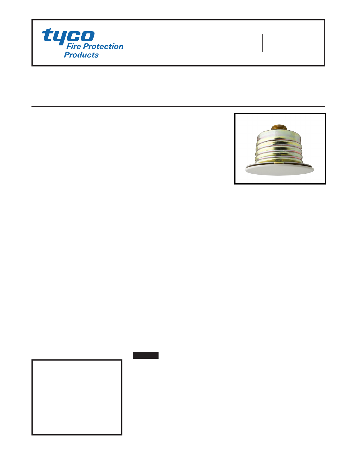
Damage to the Solder Link Element dur-
ing installation can be avoided by han-
dling the sprinkler by the Support Cup
only; that is, do not apply pressure to the
Solder Link Element (Figure 1).
A leak-tight 1/2 inch NPT sprinkler joint
should be obtained by applying a min-
imum-to-maximum torque of 7 to 14
ft.-lbs. (9,5 to 19,0 Nm). Higher levels
of torque can distort the sprinkler inlet
with consequent leakage or impairment
of the sprinkler.
Do not attempt to compensate for insuf-
cient adjustment in the Cover Plate/
Retainer Assembly by under- or over-
tightening the sprinkler. Re-adjust the
position of the sprinkler tting to suit.
Step 1. Install pendent sprinklers in
the pendent position, with the center-
line of the sprinkler perpendicular to the
mounting surface.
Step 2. Remove the Protective Cap.
Step 3. With pipe-thread sealant ap-
plied to the pipe threads, and using the
W-Type 18 Wrench shown in Figure 2,
install and tighten the Sprinkler/Sup-
port Cup Assembly into the tting. The
W-Type 18 Wrench accepts a 1/2 inch
ratchet drive.
Step 4. Replace the Protective Cap by
pushing it upwards until it bottoms out
against the Support Cup. The Protec-
tive Cap helps prevent damage to the
Deector and Guide Pins during ceiling
installation and/or during application of
the nish coating of the ceiling.
NOTICE
As long as the protective Cap remains
in place, the system is considered “Out
Of Service”.
Step 5. After the ceiling has been com-
pleted with the 2-1/2 inch (63 mm) diam-
eter hole and in preparation for install-
ing the Cover Plate/Retainer Assembly,
remove and discard the Protective Cap,
and verify that the Deector moves up
and down freely.
If the sprinkler has been damaged and
the deector does not move up and
down freely, replace the entire sprinkler
assembly. Do not attempt to modify or
repair a damaged sprinkler.
Step 6. Screw on the Cover Plate/Re-
tainer Assembly until its ange contacts
the ceiling. Do not continue to screw
on the Cover Plate/Retainer Assembly
such that it lifts a ceiling panel out of
its normal position.
If the Cover Plate/Retainer Assembly
cannot be engaged with the Mounting
Cup or the Cover Plate/Retainer Assem-
bly cannot be engaged sufciently to
contact the ceiling, the Sprinkler Fitting
must be repositioned.
Care and
Maintenance
The TYCO RAPID RESPONSE
Series
LFII Residential Flat-Plate Concealed
Pendent Sprinkler (TY2524) must be
maintained and serviced in accordance
with ths section:
Before closing a re protection system
main control valve for maintenance work
on the re protection system that it con-
trols, obtain permission to shut down the
affected re protection system from the
proper authorities and notify all person-
nel who may be affected by this action.
Absence of a Cover Plate may delay the
sprinkler operation in a re situation.
The owner must assure that the sprin-
klers are not used for hanging any ob-
jects and that the sprinklers are only
cleaned by means of gently dusting with
a feather duster; otherwise, non-opera-
tion in the event of a re or inadvertent
operation may result.
When properly installed, there is a nomi-
nal 1/8 inch (3,2 mm) air gap between
the lip of the Cover Plate and the ceil-
ing, as shown in Figure 3. This air gap
is necessary for proper operation of the
sprinkler by allowing heat ow from a
re to pass below and above the Cover
Plate to help assure appropriate release
of the Cover Plate in a re situation. If the
ceiling needs repainting after sprinkler
installation, exercise care to ensure that
the new paint does not seal off any of
the air gap. Failure to do so may impair
sprinkler operation.
Factory painted Cover Plates must not
be repainted. They should be replaced,
if necessary, by factory painted units.
Non-factory applied paint may adversely
delay or prevent sprinkler operation in
the event of a re.
Do not pull the Cover Plate relative to the
Retainer. Separation may result.
Sprinklers which are found to be leaking
or exhibiting visible signs of corrosion
must be replaced.
Automatic sprinklers must never be
painted, plated, coated, or otherwise
altered after leaving the factory. Modi-
ed or overheated sprinklers must be
replaced.
Care must be exercised to avoid dam-
age to the sprinklers - before, during,
and after installation. Sprinklers dam-
aged by dropping, striking, wrench twist/
slippage, or the like, must be replaced.
The owner is responsible for the in-
spection, testing, and maintenance of
their re protection system and devices
in compliance with this document, as
well as with the applicable standards of
the National Fire Protection Association
(e.g., NFPA 25), in addition to the stan-
dards of any other authorities having ju-
risdiction. Contact the installing contrac-
tor or sprinkler manufacturer regarding
any questions.
Automatic sprinkler systems are rec-
ommended to be inspected, tested,
and maintained by a qualied Inspec-
tion Service in accordance with local
requirements and/or national codes
.

TFP443
Page 6 of 6
Limited
Warranty
For warranty terms and conditions, visit
www.tyco-re.com.
Ordering
Procedure
Contact your local distributor for avail-
ability. When placing an order, indicate
the full product description and Part
Number (P/N).
Sprinkler/Support Cup Assembly
Specify: Series LFII (TY2524), K = 4.9
(70,6), Residential Flat-Plate Concealed
Pendent Sprinkler without Cover Plate/
Retainer Assembly, P/N 51-114-1-160
Cover Plate/Retainer Assembly
Specify: Series LFII (TY2524), K = 4.9
(70,6), Residential Flat-Plate Concealed
Pendent Sprinkler Cover Plate/Retain-
er Assembly with (specify) nish, P/N
(specify):
Ivory (RAL 1015)........... P/N 56-202-0-135
Beige (RAL 1001) .......... P/N 56-202-2-135
Pure White (b) (RAL 9010) ... P/N 56-202-3-135
Signal White (a) (RAL 9003) .. P/N 56-202-4-135
Grey White (RAL 9002) ..... P/N 56-202-5-135
Brown (RAL 8028) ......... P/N 56-202-6-135
Black (RAL 9005) .......... P/N 56-202-7-135
Brushed Brass ............ P/N 56-202-8-135
Brushed Chrome .......... P/N 56-202-9-135
Custom Paint ............. P/N 56-202-X-135
(a) Previously known as Bright White.
(b) Eastern Hemisphere sales only.
Note: All Custom Cover Plates are
painted using Sherwin Williams Interior
Latex Paint. Contact TYCO Customer
Service with any questions related to
custom orders.
Sprinkler Wrench
Specify: W-Type 18 Sprinkler Wrench,
P/N 56-000-1-265
This manual suits for next models
1
Table of contents
Popular Fire Alarm manuals by other brands

Bosch
Bosch FPA-1000-UL Installation and operation guide

Teletek electronics
Teletek electronics SensoIRIS BSOU IS Installation instruction

Zeta Alarm Systems
Zeta Alarm Systems Simplicity Plus 64 installation manual

Eaton
Eaton CF2000 installation manual

Kidde Fire Protection
Kidde Fire Protection ANTARES manual

First Alert
First Alert FA2000C user manual

Simplex
Simplex SafeLINC 4100U Application guide

Cooper Notification
Cooper Notification RSS-241575W instruction manual

FireClass
FireClass FC430SB quick start guide

Panasonic
Panasonic EBL512 operating instructions

Honeywell
Honeywell GENT Vigilon Plus Series operating instructions

Bosch
Bosch FPC-500 Operation manual