HydroVerge Hydrant Buddy Instruction sheet

Read these instructions thoroughly before using the Hydrant Buddy. For more in-
product is sold with the understanding that the purchaser agrees to thoroughly
train all operators and maintenance personnel in the correct and safe assembly,
operation, and maintenance of the product and to provide adequate supervision of
personnel at all times. Retain these instructions for future reference. If this product
is resold or otherwise conveyed, purchaser must pass on the instructions to the
new user.
PRODUCT INSTRUCTIONS
The Hydrant Buddy Kit Includes:
• Hydrant Buddy Tool
• Batteries (2)
• Charger
• Socket
• Hex Key
• Wrench
• Grease Zerk
• Product Instructions
• Tool Bag or Crate

2HV-0104January2021
Table of Contents
Section 1: Safety .........................................................................3
Section 2: Product Specifications...............................................4
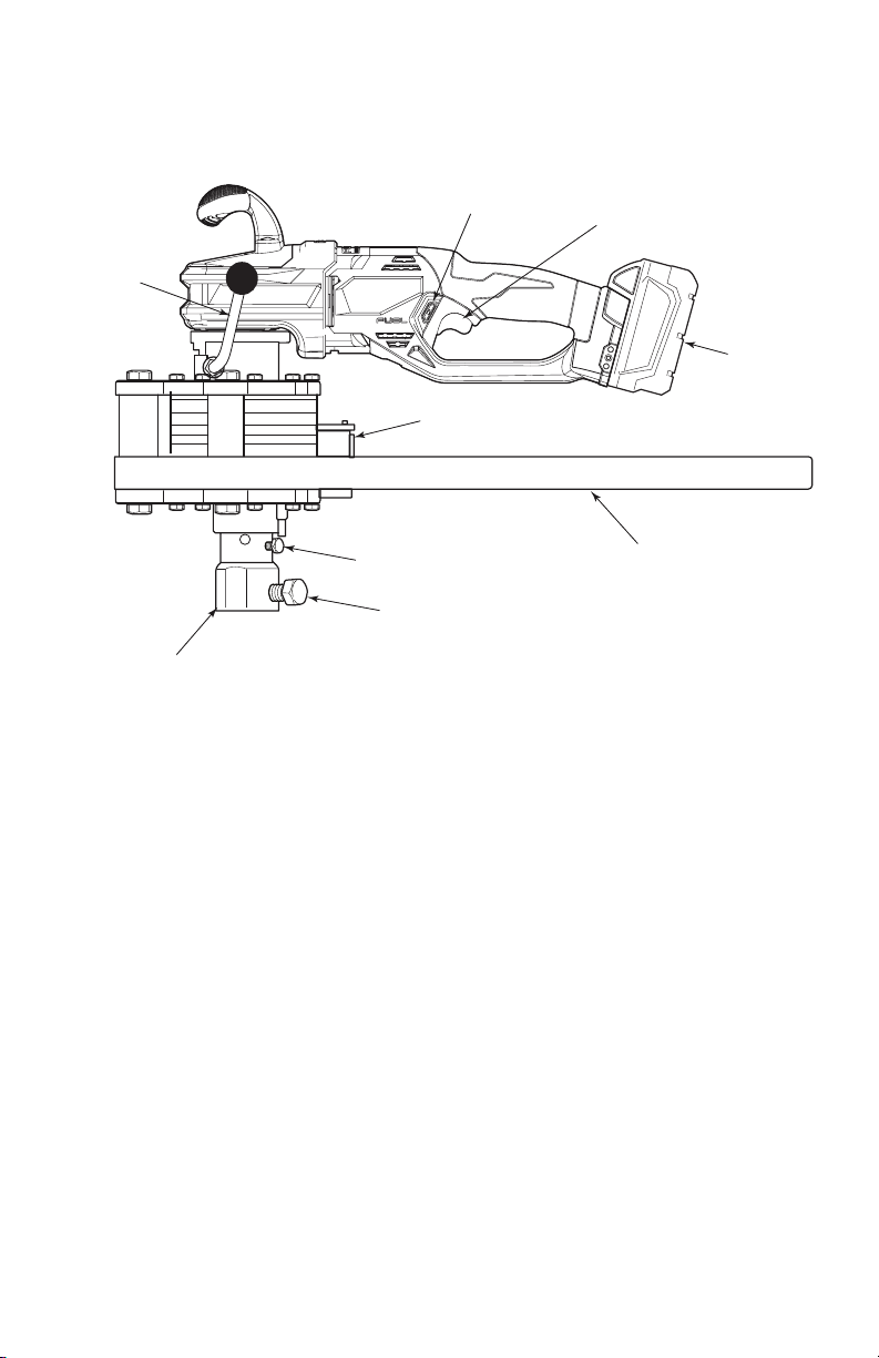
Section 3: Components................................................................5
Section 4: Hydrant Buddy Controls.............................................6
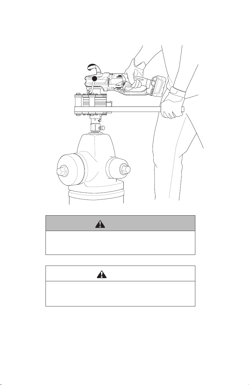
Section 5: Operation ....................................................................7
Opening Hydrant Valves.............................................................8
Closing Hydrant Valves...............................................................9
Section 6: Other Attachments ...................................................10
Attachment Options .................................................................10
Gate Valve Key.........................................................................11
Section 7: Maintenance.............................................................14
Greasing the Output Drive........................................................14
Greasing the Output Drive Housing ..........................................15
Section 8: Reference Tables......................................................16
Gate Valve Tables.....................................................................16
Section 9: Troubleshooting........................................................18

3HV-104January 2021
Section 1: Safety
The Hydrant Buddy is designed to produce an intense amount of torque.
PLEASE USE EXTREME CAUTION AT ALL TIMES.
This tool has been designed to help operators open and close valves.
The tool can create in excess of 450 lb-ft of torque.
DANGER
The incorrect use of HydroVerge equipment may cause serious
injury. Read these instructions in their entirety before using any
HydroVerge products.
WARNING
Use caution when operating any power tool. Read and follow the
operating and safety instructions in the product manual. Always
wear safety goggles and other appropriate safety items for
protection.
CAUTION
Never apply manual torque to open or close a valve! ONLY USE
MOTOR POWER TO ACTUATE THE VALVE, OTHERWISE, DAMAGE
TO THE MOTOR MAY OCCUR.
WARNING
MAKE SURE THE REACTION HANDLE IS PULLING AWAY FROM
THE OPERATOR DURING USE. Misuse could lead to loss of
operator balance and potential fall injury.

4HV-0104January2021
Section 2: Product Specifications
Model Name Hydrant Buddy
Model Type Cordless
Width (in) 6.5”
Length (in) 26”
Height (in) 12” from output drive to top motor handle
Weight 22.5 lbs with socket and battery
Battery Capacity Up to 20 hydrants / 10 gate valves
Battery Charge Time 65 minutes
Variable Speed Up to 30 rpms
Torque Up to 400 lb-ft
NOTE: This is lower then Section 1 states because
this is the torque the tool starts out with. Over time,
the tool will have less friction and more torque.

5HV-104January 2021
Section 3: Components
;NJM]QN\NRW\][^L]RXW\]QX[X^PQUbKNOX[N^\RWP]QN1bM[JW]+^MMb/X[VX[NRWÏ
OX[VJ]RXWLJUU1bM[X?N[PNJ]"!Ï!X[NVJRU3NOO)1bM[X?N[PNLXV=QR\
Y[XM^L]R\\XUM`R]Q]QN^WMN[\]JWMRWP]QJ]]QNY^[LQJ\N[JP[NN\]X]QX[X^PQUb
][JRWJUUXYN[J]X[\JWMVJRW]NWJWLNYN[\XWWNURW]QNLX[[NL]JWM\JONJ\\NVKUb
XYN[J]RXWJWMVJRW]NWJWLNXO]QNY[XM^L]JWM]XY[X_RMNJMNZ^J]N\^YN[_R\RXWXO
YN[\XWWNUJ]JUU]RVN\;N]JRW]QN\NRW\][^L]RXW\OX[O^]^[N[NON[NWLN2O]QR\Y[XM^L]
R\[N\XUMX[X]QN[`R\NLXW_NbNMY^[LQJ\N[V^\]YJ\\XW]QNRW\][^L]RXW\]X]QN
WN`^\N[
9;8->,=27<=;>,=287<
=QN1bM[JW]+^MMb4R]2WLU^MN\#
v 1bM[JW]+^MMb=XXU
v +J]]N[RN\
v ,QJ[PN[
v <XLTN]
v 1Na@[NWLQ
v 0[NJ\N/R]]RWP
v 6JPWN]\
v 6JW^JU
CHARGER
WRENCH
GREASE
ZERK
BATTERIES (2)
TOOL BAG OR CRATE
(Not Pictured)
PRODUCT
INSTRUCTIONS
HYDRANT
BUDDY
5-POINT
ADJUSTABLE
SOCKET
HEX KEY

6HV-0104January2021
Section 4: Hydrant Buddy Controls
ROTATION FORCE AWAY FROM OPERATOR
Threaded
Fastener
Set Screw
Battery
Reaction
Handle
Socket
Directional Switch
Trigger
Digital Counter
Handle
Lock

7HV-104January 2021
Section 5: Operation
WARNING
MAKE SURE THE REACTION HANDLE IS PULLING AWAY FROM
THE OPERATOR DURING USE. Misuse could lead to loss of
operator balance and potential fall injury.
CAUTION
Never apply manual torque to open or close a valve! ONLY USE
MOTOR POWER TO ACTUATE THE VALVE, OTHERWISE, DAMAGE
TO THE MOTOR MAY OCCUR.
Follow all Hydrant Buddy procedures outlined in these Product
Instructions. Failure to follow product usage instructions, including
manually turning the valve, will invalidate the product warranty.

8HV-0104January2021
Opening Hydrant Valves
1. Insert the socket onto the Hydrant Buddy 3/4” square drive shaft.
2. Tighten the set screw to secure the socket.
3. Place the Hydrant Buddy with the socket onto the hydrant with the
reaction handle facing away from the operator.
4. Adjust socket size by turning threaded fastener.
5. Zero out the digital rotation counter.
6. Move the directional switch to the left for counter clockwise rotation
or to the right for clockwise rotation.
7. Operate the Hydrant Buddy to open the hydrant valve, slowing down
as it nears the fully open position. See the hydrant manufacturer’s
specifications to determine the approximate number of valve rota-
tions.

9HV-104January 2021
8. After the valve has been opened completely, note the rotation count
on the digital display.
9. Zero out the digital rotation counter.
Closing Hydrant Valves
1. Move the handle lock to the “unlocked” position and swing the reac-
tion handle to the opposite side of the Hydrant Buddy.
Handle
Lock
UNLOCKED
LOCKED
2. Now, move the handle lock to the “locked” position. This sets the
handle facing away from the operator.
3. Move the directional switch in the opposite direction used for open-
ing.
4. Operate the tool carefully to close the hydrant valve, slowing down as
it nears the fully closed position.
5. Stop the Hydrant Buddy when the digital counter reaches the previ-
ously noted counter value.
NOTE: Be aware the torque will increase if you go over the previ-
ously noted counter value because now the hydrant valve is being
over-tightened and could potentially break or bind the valve.
6. Remove the Hydrant Buddy from the hydrant valve.

10 HV-0104 January 2021
Section 6: Other Attachments
Attachment Options
ROTATION FORCE AWAY FROM OPERATOR
HBS-5A
Adjustable
5-point Socket
(Included with Tool)
GVK-L
78"-135"
Depth Capacity
GVK-S
48"-82"
Depth Capacity
HBS-3A
Adjustable
3-point Socket
HBS-114
1-1/4"
4-point Socket
HBS-1M
3/4” Female to
1” Male Adapter

11HV-104January 2021
Gate Valve Key
The gate valve key can be purchased separately. It fits onto the Hydrant
Buddy and opens gate valves.

12 HV-0104 January 2021
Exercising Gate Valves - Part I
1. Place the gate valve key onto the operating nut.
2. Adjust the length of the key to ensure the top of the key is at a com-
fortable height for the operator.
3. Ensure the Hydrant Buddy tool is fully seated on the gate valve key
with the reaction handle facing away from the operator.
4. Zero out the digital rotation counter.
5. Move the directional switch to the left for counter clockwise rotation
or to the right for clockwise rotation.
6. Operate the Hydrant Buddy to begin exercising the gate valve, slow-
ing down as it nears the fully open or closed position. See “Section
8: Reference Tables” on page 16 to determine the approximate
number of valve rotations.
7. After the valve has been open or closed completely, note the rotation
count on the digital display.
8. Zero out the digital rotation counter.

13HV-104January 2021
Exercising Gate Valves - Part II
1. Move the handle lock to the “unlocked” position and swing the reac-
tion handle to the opposite side of the Hydrant Buddy.
Handle
Lock
UNLOCKED
LOCKED
2. Now, move the handle lock to the “locked” position. This sets the
handle facing away from the operator.
3. Move the directional switch in the opposite direction used in Part I.
4. Operate the tool carefully to open or close the gate valve.
5. Stop the Hydrant Buddy when the digital counter reaches the previ-
ously noted counter value, slowing down as it nears the fully open/
closed position.
NOTE: Be aware the torque will increase if you go over the previ-
ously noted counter value because now the gate valve is being over-
torqued and could potentially break or bind the valve.
6. Remove the Hydrant Buddy from the gate valve.

14 HV-0104 January 2021
Section 7: Maintenance
Greasing the Output Drive & Output Drive Housing
For proper operation the Hydrant Buddy should be greased in two
locations every 12 months.
Greasing the Output Drive
1. Using included Hex Key, remove the threaded plug from output drive.
2. Insert the grease zerk into the output drive threaded hole.
3. Attach a grease pump containing ThrmaPlex Hi-load - Item #70414.

15HV-104January 2021
4. Pump 1 oz. of grease.
5. Disconnect the grease pump.
6. Rotate the output drive by slowly operating the Hydrant Buddy motor.
7. Repeat steps 3-6 four more times.
8. Remove the grease zerk.
9. Insert the threaded plug back into the output drive threaded hole and
tighten with the hex key.
10. Wipe off the excess grease from the exterior of the gearbox.
Greasing the Output Drive Housing
1. Attach a grease pump to the zerk fitting already installed on the
output drive housing.
2. Pump 1 oz. of grease into the output drive.
3. Disconnect the grease pump.
4. Wipe off the excess grease from the exterior of the output drive hous-
ing.

16 HV-0104 January 2021
Section 8: Reference Tables
Gate Valve Tables
NOTE: The following tables are for reference only. For more accurate
information, see the specific hydrant manufacturer to determine the
number of valve rotations.
Most Double Disk Valves Used in Water Systems
Valve Size Number of Turns
3” 7-1/2
4” 14-1/2
6” 20-1/2
8” 27
10” 33-1/2
12” 38-1/2
14” 46
16” 53
18” 59
20” 65

17HV-104January 2021
Most Metal-Seated Sewage Valves
Valve Size Number of Turns
3” 11
4” 14
6” 20
8” 27
10” 33
12” 38
14” 46
16” 53
18” 57
20” 65

18 HV-0104 January 2021
Section 9: Troubleshooting
Problem Remedy
Motor is loose and
rotates freely
Tighten the lock handle nut slightly so when open
it can be moved, but when closed the handle is
tight.
Counter not counting Ensure the magnet is properly located on the
socket so the counter can catch each rotation.
Please call HydroVerge at 952-484-8610 at any time with questions.
We are available and eager to answer your questions about the proper
use of the Hydrant Buddy, as well as, solve any problems you may have
with the tool.


HV-721_HydrantBuddy_Rev01/21
For the latest in Hydrant Buddy product news and insights,
visit our website at www.HydroVerge.com. For more information,
call HydroVerge at (952) 484-8610 or email info@HydroVerge.com.
P
a
t
e
n
t
#
8
6
7
7
8
6
2
Table of contents