3
STEP 5: If pole mounting the enclosure, assemble the pole mount kit to
the back of the enclosure and mount the enclosure to a pole using the 6
hose clamps provided. The enclosure can also be wall mounted using
the 4 holes in the back of the enclosure.
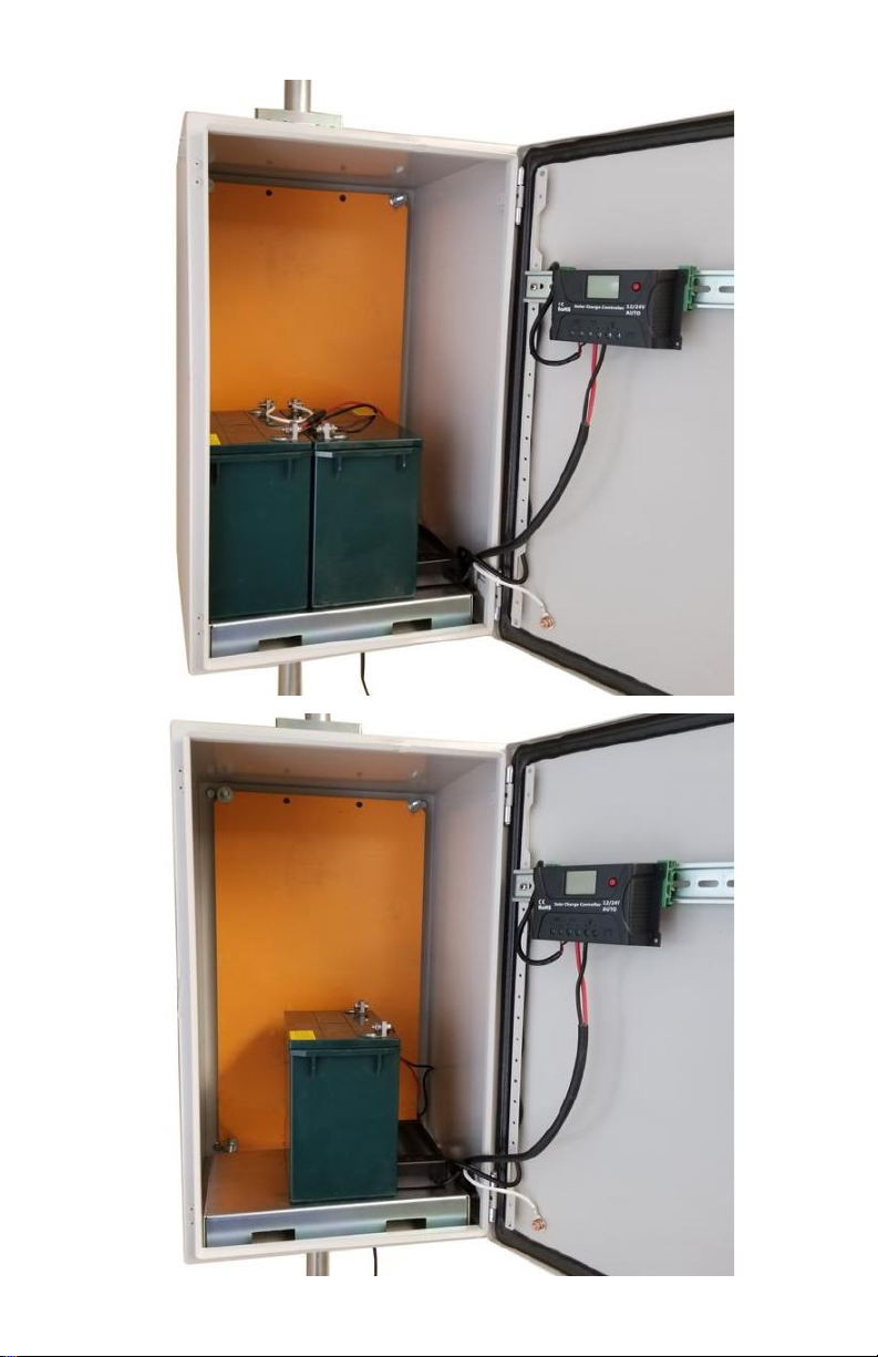
STEP 6: Insert the battery platform in
the bottom of the enclosure. The bat-
tery platform has cutouts so wires
can be routed under the battery as
needed.
STEP 7: Attach the Green DIN Rail adapters to the charge controller
using the screws provided. Use 1 screw per adapter. Clip the controller
to the DIN rail.
STEP 8: Install 1 or 2 batteries in a 12V or 24V configuration, depend-
ing on which system you purchased. Remove the battery cable fuse
before connecting the batteries to avoid any accidental shorting. Con-
nect battery cables and PowerVent fan cables to the Solar Controller
battery input (Battery Symbol), then to battery terminals. Observe prop-
er polarity. Red wire is always V+.
STEP 9: Connect the 120W 12V or 24V battery charger to the Solar
Controller PV input (Solar Panel Symbol). Make sure to observe proper
polarity. Red wire is always V+. The controller has a pluggable 2 wire
AC cord. You can cut this cord to hardwire into the mains. You can also
mount conduit to the enclosure if local codes require it. During opera-
tion the charger will be very warm to the touch. This is normal.
STEP 10: Mount any customer electronics to the inside of the enclo-
sure. Connect any loads to the Solar Controller LOAD output. (Light
Bulb Symbol). Press red button to turn on/off the LOAD output.
Note: There are multiple cable gland feedthrough in the bottom of the
enclosure. If you are not using any of the feedthrough you can cut a
short piece of wire, put it through the cable gland and tighten the cable
gland on the wire to seal it.
STEP 11: Double check wiring and then re-install the battery cable fuse
to energize the system, The solar controller display shows battery volt-
age, charging current, load current and temperature.
CAUTION: Reverse polarity connections will damage the equip-
ment.
STEP 12: Make sure lid gasket is clean and free from any particles,
then close the cover, making sure that wires are clear of the seam and
hinge area.
STEP 13: The UPSPro® is Solar Ready™ so a solar panel can be add-
ed at any time to provide supplemental or full time power. Solar panel
will be connected to PV input (Solar Panel Symbol) in parallel with AC
Power supply. Solar panels must have blocking diodes which is the
standard for most solar panels.


 Plus Startup manual")


