TYCON Solar UPSPro UPS-ST-600 User manual

UPS-ST-600
UPSPro®
Outdoor UPS System
▫Wireless Base Stations
and Client Devices
▫Surveillance Cameras
▫Mission Critical Backup
Power
▫Remote Sensors
Congratulations! on your purchase of the UPSPro®Outdoor
UPS backup power system. Please take a moment to review this
Qwik Install Guide before assembly or battery installation.
DANGER! Avoid Powerlines!
You Can Be Killed!
When following the instructions in this guide take extreme care
to avoid contact with overhead power lines, lights and power circuits.
Contact with power lines, lights or power circuits may be fatal. We rec-
ommend to install no closer than 20 feet to any power lines.
Safety: For your own protection, follow these safety rules.
▫Perform as many functions as possible on the ground
▫Do not attempt to install on a rainy, windy or snowy day or if
there is ice or snow accumulation at the install site or if the
site is wet.
▫Make sure there are no people, pets, etc. below when you are
working on a roof or ladder.
Recommended Tools: Phillips Screwdriver, Flat Blade Screw-
driver, 13mm and 10mm Wrench, 5/16” nut driver,
Please help preserve the environment and return
used batteries to an authorized depot

2
Qwik Install
STEP 1: Add Grounding Wire Between Door and Enclosure: Remove
plastic covers on copper studs on
inside of door and inside of enclo-
sure. Add jumper wire between 2
copper studs and use copper wash-
ers and nuts to secure.
STEP 2: Remove the bottom cover
and replace it with the PowerVent™
included with the package. Add wire
feedthrus and any necessary con-
nectors into the bottom PowerVent™
plate.
STEP 3: Install hole plug in drain
hole in bottom right corner of the en-
closure.
STEP 4: Mount the DIN rail to the
door using screws provided. Mount
any extra equipment to the orange
backplate and secure the backplate in
the enclosure. Note: The DIN rail can
also be mounted to the orange back-
plate or sides of enclosure if desired.
STEP 5: If pole mounting the enclo-
sure, assemble the pole mount kit to
the back of the enclosure and mount
the enclosure to a pole using the 6 hose clamps provided. The enclo-
sure can also be wall mounted using the 4 holes in the back of the en-
closure.

3
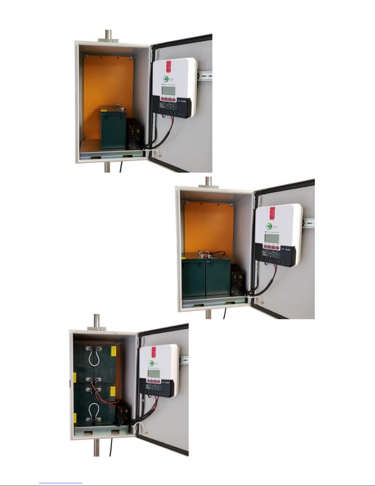
STEP 6: Insert the battery platform
in the bottom of the enclosure. The
battery platform has cutouts so
wires can be routed under the bat-
tery as needed.
STEP 7: Attach the Black DIN Rail adapters to the charge controller
using the screws provided. Use 3 screws per adapter. Clip the control-
ler to the DIN rail by hooking the bottom under the DIN rail then lifting
the controller up and over the top lip of the DIN Rail.
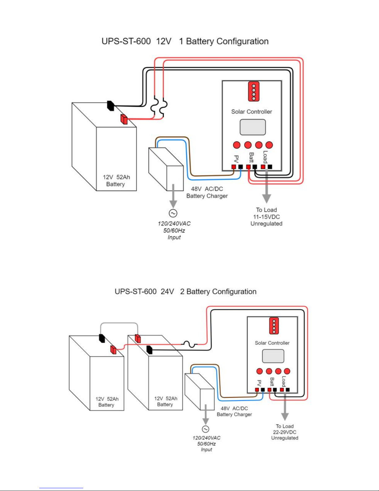
STEP 8: Install 1 or 2 or 4 batteries in a 12V or 24V configuration, de-
pending on which system you purchased. Remove the battery cable
fuse before connecting the batteries to avoid any accidental shorting.
Connect battery cables and PowerVent fan cables to the Solar Control-
ler battery input (BAT+ & BAT-), then to battery terminals. Observe
proper polarity. Red wire is always V+. If two battery cables are sup-
plied with the system you must use both cables. If batteries are mount-
ed on their side use a rubber bumper on each terminal to prevent
shorts.
STEP 9: Connect the 600W 48V battery charger to the Solar Controller
PV input (PV+ & PV-). Make sure to observe proper polarity. Brown
wire is V+. The controller has a pluggable 3 wire AC cord. You can cut
this cord to hardwire into the mains. You can also mount conduit to the
enclosure if local codes require it. During operation the charger fan may
run. This is normal.
STEP 10: Mount any customer electronics to the inside of the enclo-
sure. Connect any loads to the Solar Controller LOAD output. (LOAD+
& LOAD-). Press red SET button to turn on/off the LOAD output.
Note: There are multiple cable gland feedthrough in the bottom of the
enclosure. If you are not using any of the feedthrough you can cut a
short piece of wire, put it through the cable gland and tighten the cable
gland on the wire to seal it.
STEP 11: Double check wiring and then re-install the battery cable fuse
to energize the system, The solar controller display shows battery volt-
age, charging voltage, charging current, load current and temperature.
CAUTION: Reverse polarity will damage the equipment.
STEP 12: Make sure lid gasket is clean and free from any particles,
then close the cover, making sure that wires are clear of the seam and
hinge area.
STEP 13: The UPSPro® is Solar Ready™ so a solar panel can be add-
ed to provide supplemental or full time power. The solar panel will be
connected to PV input (PV+ & PV-) in parallel with AC Battery Charger.
The solar panel PV+ must be connected to the solar controller through
an 80V-100V blocking diode (Tycon PN 5600059) to prevent reverse
current to the solar panel.

4
UPS-ST12-50-600
1 Battery
UPS-ST24-50-600
2 Battery
UPS-ST24-100-600
4 Battery

5
SPECIFICATIONS Subject to change without notice
Battery Voltage (DC) 12V or 24V
Load Output Voltage (DC) 11-15VDC / 22-29VDC
Suggested Max Load 450W
AC Input Voltage 120/240VAC 50/60Hz 5A Max
Battery Charge Voltage 14.4V / 28.8V
Battery Charge Current 40A / 20A
Battery Charge Capacity 600W
Capacity (Ah) @ 12V 50Ah to 200Ah
Battery Type Valve Regulated Sealed Lead
Acid / Absorbent Glass Mat (AGM)
Battery Life 5 Years
Controller Type 40A MPPT with status display and
load control
Overcharge Protection 14.4V / 28.8V
Over-discharge protection 11V / 22V
Over-discharge recovery voltage 12.6V / 25.2V
Controller Self Consumption <1W
Enclosure Type Powder Coated Steel
Enclosure External Size 24 x 15 x 14"
(610 x 381 x 356mm)
Enclosure Internal Size 23 x 14 x 12"
(584 x 356 x 305mm)
Operating Temperature -30°C to +60°C
System Weight (without batteries) 55lb (25kg)
Battery Weight (each) 37lb (17kg)

6

7
TECH CORNER
1.CONTROLLER: The controller turns off power to the load at 11V
(22V if 24V array) and reconnects when the battery reaches 12.6V
(25.2V if 24V array). This protects battery from over-discharge and in-
creases battery life and performance.
2. CAPACITY: With a typical AP running 4W average. A single 12V
52Ah battery should be able to provide backup power for up to 75 hours
at room temperature. For cold temperatures the capacity is reduced by
20-30%.
3. VENTING: The enclosure is vented thru the included PowerVent™.
The fan is thermostatically controlled to turn on when the temperature
inside the enclosure exceeds 45C. It runs on 12V to 24VDC.
4. DUAL INPUTS: The UPS-ST-600 can be used with AC Power alone
or Solar Power alone or a combination of both.
5. SOLAR PANEL: The MPPT controller used in the UPS-ST-600 can
handle a maximum panel size of 550W @ 12V Battery or 1100W @
24V Battery. Maximum panel voltage is 90V. Do not exceed 40A into
the solar panel input of the solar controller.

8
8000071 Rev 1 UPS-ST-600 UPSPro® Qwik Install Guide
6. BATTERY HOOKUP: Always connect the battery first and discon-
nect the battery last. The controller should not be run without a battery
connected.
7. BATTERY MAINTENANCE: The batteries used in the UPSPro sys-
tems don’t require any maintenance. They should last up to 5 years in
normal use. Note: Never store batteries for any length of time in a
discharged state or it will kill the battery.
8. BATTERY OVERDISCHARGE: We highly recommend hooking all
equipment loads to the controller load output. This output will discon-
nect the load if the battery voltage is too low and this will protect the
battery from over-discharge. If batteries get completely discharged be-
cause the equipment was connected directly to the battery, you will re-
duce the battery life.
9. LOAD OUTPUT: The LOAD output on the Solar Charge Controller is
unregulated. What that means is the voltage output follows the battery
voltage. This is typically 11-15V for a 12V system and 22-29V for a 24V
system. It is up to the user to make sure the connected load is compati-
ble with these voltages. A voltage regulator can be added to provide
regulated output voltages.
Limited Warranty
The UPSPro® products are supplied with a limited 36 month warranty
which covers material and workmanship defects. This warranty does
not cover the following:
▫Parts requiring replacement due to improper installation, misuse, poor site
conditions, faulty power, etc.
▫Lightning or weather damage.
▫Physical damage to the external & internal parts.
▫Products that have been opened, altered, or defaced.
▫Water damage for units that were not mounted according to user manual.
▫Usage other than in accordance with instructions and the normal intended
use.
NOTES
Table of contents
Other TYCON Solar UPS manuals