We declare this product complies with the relevant UK
legislation on condition that it is used in the manner
intended, and in accordance with the current installation
standards and/or the manufacturer's recommendations.
A copy of the full UKCA Declaration of Conformity is
available on request.
Pet Alley Mode
To prevent pets causing false
activations the PIR must be
fitted at low level (1m) and
have its internal PCB set to
the PET ALLEY position.
Undo screw and slide the PCB
down into the PET ALLEY position.
When fitted in this mode any
movement below the 1m level
will go un-detected.
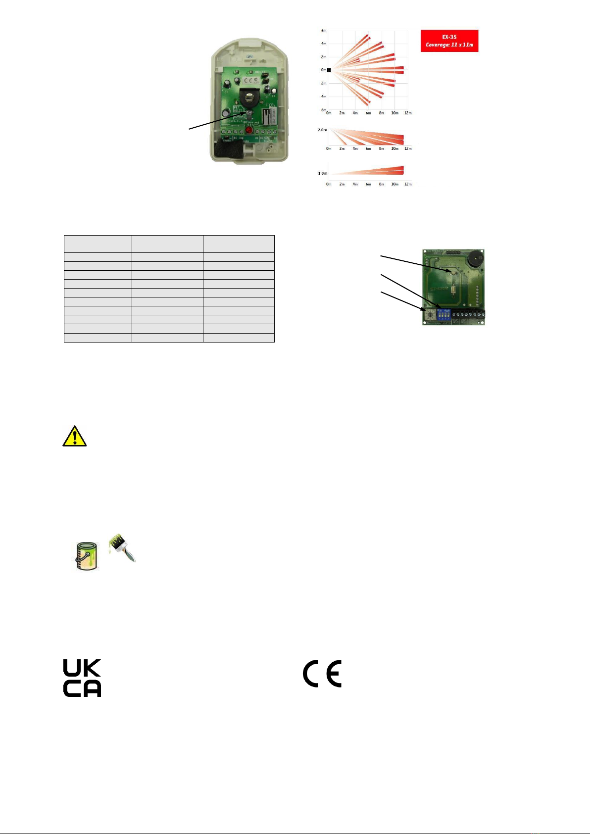
Setting the Alarm Delay
Turn the rotary switch to set the delay before alarm. With DIL switch 1 OFF the LED will FLASH GREEN to indicate the number of
minutes delay, with DIL switch 1 ON the LED will FLASH RED to indicate the number of minutes delay x10. Position 0 = test mode.
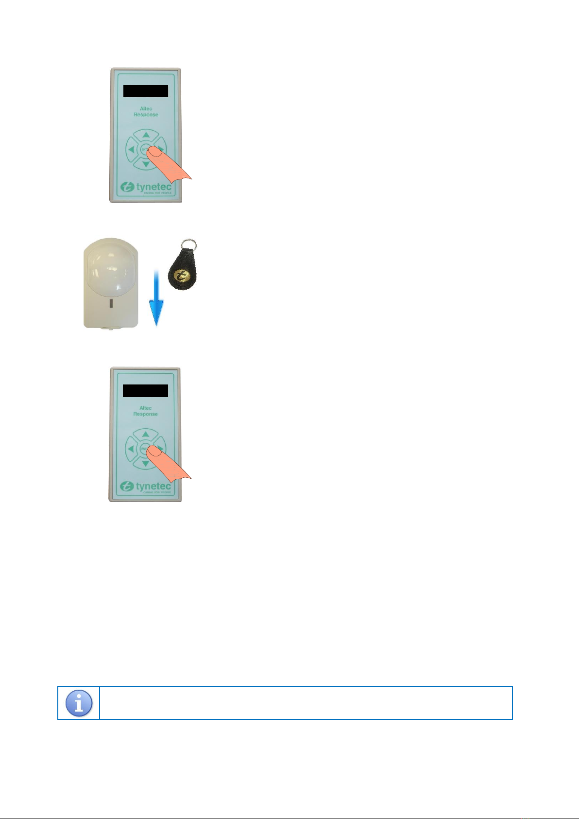
Testing & Registering a Property Exit Sensor
A “door exit” and “door open” alarm must be transmitted when learning the property exit sensor onto the Reach at-home alarm
or the Altec Response local carer alarm, see pages 4 & 5 for how to put these products into “Learn Mode”.
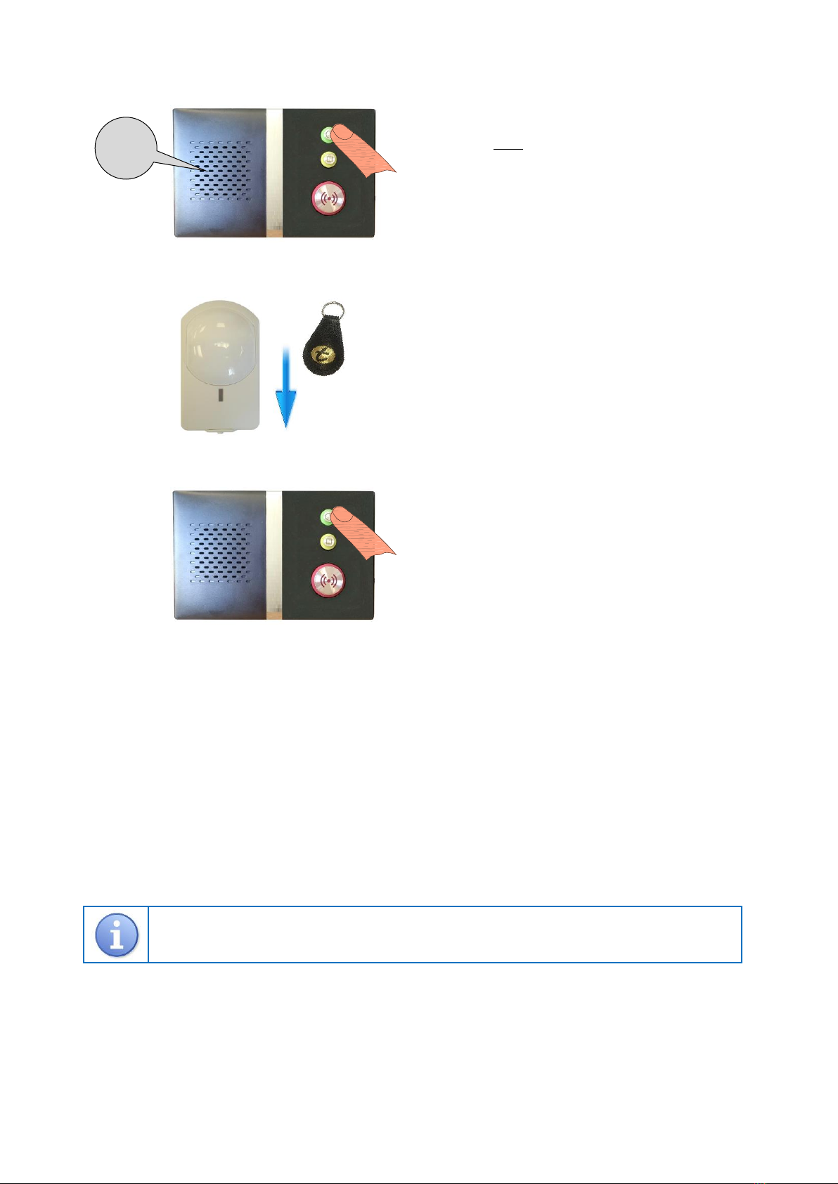
With the front door CLOSED swipe the PIR down the RIGHT HAND SIDE with the magnetic fob, with each swipe the PIR will
alternate between transmitting “door exit”(code 34) and “door open” (code 58) alarms.
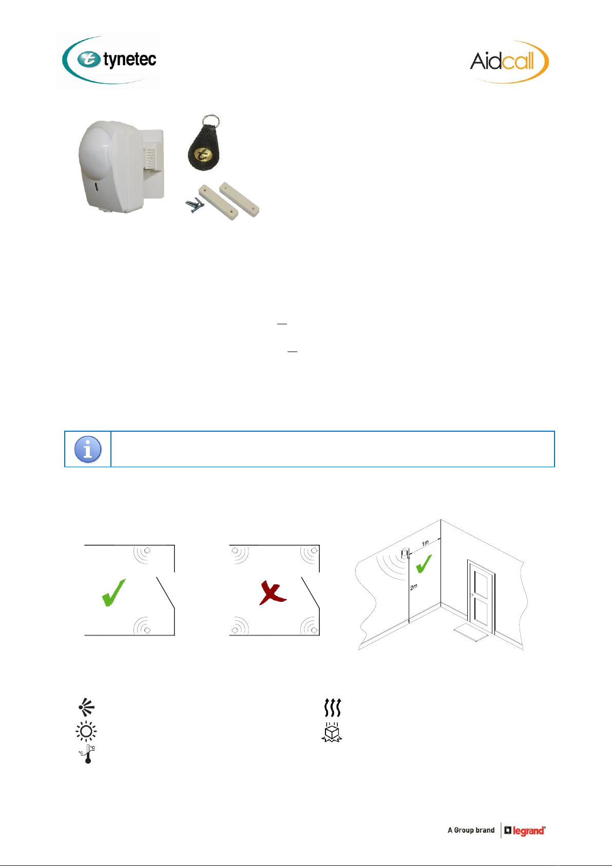
The range of all radio devices can be affected by the working environment - always take care during installation and
perform several test calls.
Maintenance
No routine maintenance is required; however a walk test should be performed once a year to verify operation.
PIR’s are not as susceptible to dust and contamination as some detectors but it is still recommended to clean them periodically.
PIR’s can be dusted or wiped clean with a damp cloth, never use detergents or polish.
Decorating
Never paint the PIR detector itself.
Unlike some detectors, PIR’s are not susceptible to contamination from paint fumes
therefore no special precautions need to be taken.
Battery Life
The PIR battery is checked once a day, if the voltage falls and stays below a pre-set level for 7 consecutive days a low battery alert
is automatically transmitted. Once a low battery call is received the battery should be replaced within 7 days.
Detailed information on battery management for all Tynetec/Aidcall products is available - request Doc No. FM0630.
Declaration of Conformity
We declare this product complies with the relevant
European legislation on condition that it is used in the
manner intended, and in accordance with the current
installation standards and/or the manufacturer's
recommendations. A copy of the full CE Declaration of
Conformity is available on request.