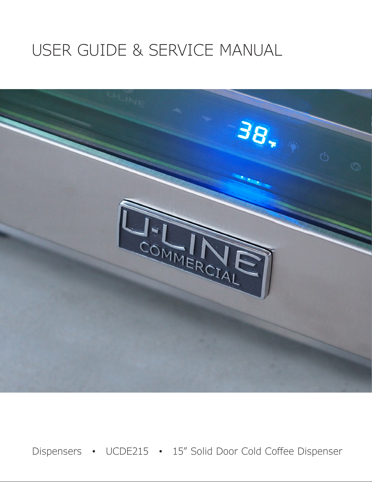
manuals.online logo
Brands
  1. Home
  2. •
  3. Brands
  4. •
  5. U-Line
  6. •
  7. Beverage Dispenser
  8. •
  9. U-Line UCDE215-SS03A Installation manual

U-Line UCDE215-SS03A Installation manual

USER GUIDE & SERVICE MANUAL
Dispensers ●UCDE215 ● 15” Solid Door Cold Coee Dispenser
Model: UCDE215-SS03A
USER GUIDE & SERVICE MANUAL
Table of Contents
Click on any section below to jump directly there
Intro
Safety
Safety and Warning
Disposal And Recycling
Installation
Environmental Requirements
Electrical
Cutout & Product Dimensions
Anti-Tip Bracket
General Installation
Grille Installation
Door Swing
Door Adjust
Maintenance
Cleaning
Cleaning Condenser
Extended Non-Use
Operating Instructions
First Use
Control Operation
Airflow and Product Loading
Service
Troubleshooting
Wire Diagram
Product Liability
Warranty Claims
Parts
Ordering Replacement Parts
R600a Specifications
System Diagnosis Guide
Compressor Specifications
Troubleshooting Extended
Control Operation - Service
Thermistor
Defrost
Remove Fan and Cover
Warranty
USER GUIDE
Introduction
WELCOME TO U-LINE
Congratulations on your U-Line purchase! Your product comes from a company with decades of premium modular ice
making, refrigeration, and wine preservation experience. U-Line creates products focused on functionality, style, and
inspired innovations — paying close attention to even the smallest details. Applications include residential, outdoor, ADA
height compliant, marine, and commercial. Product categories include Beverage Centers, Wine Refrigerators, Ice Machines,
Refrigerators, Freezers, and Dispensers. Our advanced refrigeration systems, large and exible capacities, and clean
integrated look are what makes our products Built-In to Stand Out®. Since 2014, U-Line has been part of the Middleby family
of brands. Products are designed, engineered, and assembled in Milwaukee, Wisconsin, USA, and select products are available
worldwide.
U-Line — RIGHT PRODUCT. RIGHT PLACE. RIGHT TEMPERATURE.®
PRODUCT INFORMATION
Looking for additional information on your product? User Guides, Spec Sheets, CAD Drawings, and Product Warranty
information are available digitally on u-line.com.
PROPERTY DAMAGE / INJURY CONCERNS
In the unlikely event property damage or personal injury is suspected related to a U-Line product, please take the following
steps:
1. U-Line Customer Care must be contacted immediately at +1.414.354.0300.
2. Service or repairs performed on the unit without prior written approval from U-Line is not permitted. If the unit has been
altered or repaired in the eld without prior written approval from U-Line, claims will not be eligible.
GENERAL INQUIRIES
U-Line Corporation
8900 N. 55th Street
Milwaukee, Wisconsin 53223 USA
Monday - Friday 8:00 am to 4:30 pm CST
T: +1.414.354.0300
Email: sales@u-line.com
u-line.com
CONNECT WITH US
SERVICE & PARTS ASSISTANCE
Monday - Friday 8:00 am to 4:30 pm CST
T: +1.414.354.0300
Service Email: onlineservice@u-line.com
Parts Email: onlineparts@u-line.com
Designed, engineered and assembled in WI, USA
3
USER GUIDE
Safety and Warning
Safety and Warning
NOTICE
Please read all instructions before installing,
operating, or servicing the appliance.
Use this appliance for its intended purpose only and follow
these general precautions with those listed throughout this
guide:
SAFETY ALERT DEFINITIONS
Throughout this guide are safety items labeled with a
Danger, Warning, or Caution based on the risk type:
Danger means that failure to follow this safety
statement will result in severe personal injury or
death.
Warning means that failure to follow this safety
statement could result in serious personal injury
or death.
Caution means that failure to follow this safety
statement may result in minor or moderate
personal injury, property, or equipment damage.
This unit contains R600a (Isobutane) which is a
ammable hydrocarbon. It is safe for regular
use. Do not use sharp objects to expedite
defrosting. Do not service without consulting the
“R600a specications” section included in the
User Guide. Do not damage the refrigerant
circuit.
Service must be done by factory authorized
service personnel. Any parts shall be replaced
with like components. Failure to comply could
increase the risk of possible ignition due to
incorrect parts or improper service.
CALIFORNIA PROPOSITION 65
This product contains chemicals known to the
state of California to cause cancer and birth
defects or other reproductive harm.
www.P65warnings.CA.gov
This equipment is to be installed with adequate
backow protection to comply with applicable
federal, state and local codes.
DANGER
!
DANGER
!
WARNING
!
CAUTION
!
CAUTION
!
WARNING
!
4
USER GUIDE
Disposal and Recycling
RISK OF CHILD ENTRAPMENT. Before you throw
away your old refrigerator or freezer, take o
the doors and leave shelves in place so children
may not easily climb inside.
If the unit is being removed from service for disposal,
check and obey all federal, state, and local regulations
regarding the disposal and recycling of refrigeration
appliances, and follow these steps completely:
1. Remove all consumable contents from the unit.
2. Unplug the electrical cord from its socket.
3. Remove the door(s)/drawer(s).
DANGER
!
5
USER GUIDE
Environmental Requirements
This model is intended for indoor/interior applications only
and is not to be used in installations that are open/
exposed to natural elements.
This unit is designed to operate between 50°F (10°C) and
100°F (38°C). Higher ambient temperatures may reduce
the unit’s ability to reach low temperatures and/or reduce
ice production on applicable models.
For best performance, keep the unit out of direct sunlight
and away from heat generating equipment.
In climates where high humidity and dew points are
present, condensation may appear on outside surfaces.
This is considered normal. The condensation will
evaporate when the humidity drops.
CAUTION
!
Damages caused by ambient temperatures of
40°F (4°C) or below are not covered by the
warranty.
6
USER GUIDE
Electrical
Electrical
WARNING
!
SHOCK HAZARD — Electrical Grounding
Required. Never attempt to repair or perform
maintenance on the unit until the electricity has
been disconnected.
Never remove the round grounding prong from
the plug and never use a two-prong grounding
adapter.
Altering, cutting or removing power cord,
removing power plug, or direct wiring can cause
serious injury, fire, loss of property and/or life,
and will void the warranty.
Never use an extension cord to connect power to
the unit.
Always keep your working area dry.
NOTICE
Electrical installation must observe all state and
local codes. This unit requires connection to a
grounded (three-prong), polarized receptacle
that has been placed by a qualified electrician.
The unit requires a grounded and polarized 115 VAC,
60 Hz, 15A power supply (normal household current). An
individual, properly grounded branch circuit or circuit
breaker is recommended. A GFCI (ground fault circuit
interrupter) is usually not required for fixed location
appliances and is not recommended for your unit because
it could be prone to nuisance tripping. However, be sure
to consult your local codes.
See CUTOUT & PRODUCT DIMENSIONS for recommended
receptacle location.
7
USER GUIDE
Cutout & Product Dimensions
PREPARE SITE
Your U-Line product has been designed for either free-
standing or built-in installation. When built-in, your unit
does not require additional air space for top, sides, or
rear. However, the front grille must NOT be obstructed,
and clearance is required for an electrical connection in
the rear.
CAUTION
!
Unit can NOT be installed behind a closed cabinet
door.
CUTOUT DIMENSIONS
PRODUCT DIMENSIONS
REAR
FRONT
TOP
SIDE
19 ⁄”
(507 mm)
25 ½”
(648 mm)
25 ⁄”
(660 mm)
27 ⁄”
(708 mm)
1 “ (25 mm)
2”
(51 mm)
Power
Cord
4"
(102 mm)
7"
(178 mm)
28"
(712 mm)
2 3/4”
(57 mm)
15 1⁄4"
(388 mm)
34 3⁄4"
(883 mm)
to
35 3⁄4"
(909 mm)
Preferred location
for electrical outlet
is in adjacent
cabinet.
5⁄8"
(16 mm)
2 ¾”
(70 mm)
Power Cord
7 ⁄”
(189 mm)
1”
25 mm
6”
152 mm
15”
(381 mm)
3 ⁄”
(95 mm)
28”
(711 mm) 34 ½”
(876 mm)
to
35 ½”
(902 mm)
45 ⁄”
(1,165 mm)
50 ⁄”
(1,272 mm)
1 ⁄”
(48 mm)
11”
(279 mm)
7 ½”
(191 mm)
15 ⁄”
(396 mm)
24 ¼”
(616 mm)
14 ¼”
(362 mm)
8
USER GUIDE
Anti-Tip Bracket
Anti-Tip Bracket
1. Slide unit out so screws on top of unit are easily
accessible.
2. Remove the two screws from the opposite side of the
hinge assembly using a T-25 Torx driver (see below).
3. Place bracket over holes and attach to unit with two
screws removed in step 2 using a T-25 Torx driver.
Tighten screws fully.
4. Gently push unit into position. Be careful not to
entangle the electrical cord or water line, if applicable.
5. Check to be sure the unit is level from front to back
and side to side. Make any necessary adjustments.
The unit’s top surface should be approximately 1⁄8”
(3 mm) below the countertop.
6. Secure bracket into adjoining surface.
9
USER GUIDE
General Installation
The following components are shipped inside the unit:
1. Double Tower (faucets, handles, gaskets, & hardware)
2. Nitrogen hose (1 hose clamp)
3. Infuser regulator (hoses & hardware)
 
5. Drip tray
6. Cleaning solution (2-ounce packet)
(Additional cleaner, ULACOFFEECLEAN, is available at u-line.com)
7. Four casters (2 locking, 2 non-locking)
Safety and Warning
Keep nitrogen tank in an upright position and
handle with care.
Never exceed 60 PSI.
Ventilate area after nitrogen leak.
1
2
3
4
5
6
7
Required (not included):
1. Food grade nitrogen - available at your local
gas supplier. 22 cubic feet aluminum empty
tank (ULANITROTANK) and nitrogen regulator
(ULANITROREG) are available
at u-line.com.
Note: If using an external
nitrogen source, see
CONNECTING EXTERNAL
NITROGEN SOURCE section.
2. Ball-tap keg - up to 5 gallon
3. 
tea.
General Installation
WARNING
!
10
USER GUIDE
General Installation
Install Tower on Free-Standing Refrigerator

exterior until the tower is installed.
1. Remove four Phillips screws (secured with nuts on


to clear.
2. Position gasket over mounting hole and install tower
using four Phillips screws and nuts.
3. Screw the handles onto the faucets and continue to
assemble and connect regulator to Nitrogen tank.
Gasket
11
USER GUIDE
General Installation
Install Tower on Countertop
(See template on next page)
Note: These instructions are designed for a standard 36" countertop application.
Note: For a customized t, it may be necessary to acquire screws that are sized to
the thickness of your countertop.
1. Position keg refrigerator under countertop to determine the desired depth.
2. Use the dimensions from Diagram A to determine the center point of the tower
mounting hole.
3. Remove keg refrigerator from under countertop.
4. Use template to drill 4 mounting holes and drill 3-" diameter hole through countertop.
5. Connect keg and infuser hoses to tower.
6. Pull down insulation inside tower far enough to extend into refrigerator - Diagram B.
7. Secure tower to countertop.
8. Remove hole cover from top of refrigerator.
9. Carefully slide refrigerator under countertop, taking care to insert hoses and insullation
as you go.
Front Face
of Unit
2 ¾”
(70 mm)
Hole Diameter
Power Cord
2”
(51 mm)
15”
(381 mm)
Rear Wall
24 ¼”
(616 mm)
12 ½”
(318 mm)
11 ⁄”
(283 mm)
1 ⁄”
(43 mm)
7 ½”
(19 1 mm)
Rear Wall
Countertop
11-1/8”
(283 mm)
Front edge of hole
to front face of
refrigerator
Diagram A Diagram B
Insulation
6
12
USER GUIDE
General Installation
12-1/2“
TO FRONT FACE
OF REFRIGERATOR
(SEE DIAGRAM A PREVIOUS PAGE)
7-1/2“
TO SIDE OF
REFRIGERATOR
1⁄4
” HOLE
2-3/4“ HOLE
Template for Countertop Installation
Note: Verify template has printed true to scale - double check hole dimensions and placement.
1 Inch
13
USER GUIDE
General Installation
Connecting Internal Nitrogen
Source
Install Infuser Regulator
1. Align infuser regulator with pre-drilled holes in upper
left corner of side wall. Use 2 screws to attach.
Assemble and connect tank regulator to tank
1. Attach ball valve to tank regulator (not included).
Tighten with an adjustable wrench. Make sure valve is

go.
2. Attach regulator to nitrogen tank. Hand tighten the
coupling nut and then use an adjustable wrench for an
additional quarter turn. DO NOT OVER TIGHTEN.
3. Attach nitrogen hose to ball valve on tank regulator.

clockwise as far as it can go. Tighten hose clamp.
4. Attach other end of nitrogen hose to T connector on

Connect nitrogen to keg
1. Attach gas jumper line to T connector on infuser

T-Connector
T-Connector
10
1
2
3
4
5
6789
13
14
15
12
11
Interior
Side Wall
To Tap Tower
14
USER GUIDE
General Installation
2. Attach gray coupler of the gas jumper line to keg.
With your thumb press down on the top of the coupler

onto "in" valve. Release collar - listen for a click. Pull
up on the coupler to ensure it is locked down.
3. Attach infuser hose to elbow connector on infuser
regulator.
4. Attach other end of hose to the single connection
within the beverage tower.
Elbow
Connector
Other end is
connected to
Tower
Other end is
connected
to Infuser
Regulator
In Valve
1. Attach black nitrogen coupler of the liquid jumper line
to keg. With your thumb press down on the top of
the coupler while pulling up on collar. Press coupler

for a click. Pull up on the coupler to ensure it is locked
down.
2. Attach other end of beverage hose to "Y" connection

Out Valve
Connect keg to tower
Other end is
connected to keg
15
USER GUIDE
General Installation
Connecting External Nitrogen
Source
Note: Connection to an external Nitrogen source
requires drilling one hole through the pre-
installed bulkhead located near the top of the
back wall.
Install Infuser Regulator
1. Align infuser regulator with pre-drilled holes in upper
left corner of side wall. Use 2 screws to attach.
Prepare bulkhead and back panel
1. Inside the cabinet, drill out 1 of the " holes in the
bulkhead.
2. Insert gasket ring into drilled-out hole.
3. In the back of the unit, remove back panel.
4. Insert gasket ring into hole that corresponds to the
drilled-out hole in bulkhead.
5. Inside cabinet, apply foodgrade lubricant to inside
of gasket ring in bulkhead and push nitrogen hose
through.
6. Attach nitrogen hose to infuser regulator
7. At the back of the unit, appy foodgrade lubricant to
inside of gasket ring and push nitrogen hose through.
8. Re-install back panel.
9. Connect nitrogen hose to external nitrogen source.
10. Continue with inside connections (see CONNECT
NITROGREN TO KEG in this manual)
10
1
2
3
4
5
6789
13
14
15
12
11
Interior
Side Wall
To Tap Tower
Connects
to keg
T-Connector
Connects to
external nitrogen
Outside
Inside
16
USER GUIDE
General Installation
Connections
When complete, the connections should look like this:
LEVELING INFORMATION
1. 
unit is level. Level should
be placed along top edge
and side edge as shown.
2. If the unit is not level,
shim as needed.
3. 
after each adjustment
and repeat the previous
steps until the unit is
level.
Keg
Infuser
Regulator
Filter
Assembly
To comply with applicable federal, state,
and local codes, it may be necessary to
caulk the refrigerator to the oor.
CASTERS (optional)
1. Remove grille and back panel to access nuts.
2. Remove each nut and unscrew each leg.
3. Install each caster and secure with nut.
Tighten with included wrench.
4. Replace grille and back panel.
When ready to use, see FIRST USE section in
this manual.
CAUTION
!
17
USER GUIDE
Grille Installation
Grille Installation
REMOVING AND INSTALLING GRILLE
Disconnect electric power to the unit before
removing the grille.
When using the unit, the grille must be installed.
Removing the grille
Note: Grille and display are attached. The length
of the display wire is sucient to allow access to
the front base components.
1. Disconnect power to the unit.
2. Loosen the two screws (1).
3. Remove grille (2) from unit.
Installing the grille
1. Align cabinet and grille holes and secure, but do not
over tighten grille screws (1).
2. Reconnect power to the unit.
WARNING
!
1
2
18
USER GUIDE
Door Swing
Door Swing
Units have a zero clearance for the door to open 90°,
when installed adjacent to cabinets.
Stainless Steel models require 2-1/8" (54 mm) door
clearance to accommodate the handle if installed next to a
wall.
Wall
90°
Door Swing
2-1/8" Min.
(54 mm)
19
USER GUIDE
Door Adjustments
Door Adjustments
HINGE COVER
Hinge cover included with the literature bag is optional.
To install hinge cover:
1. Press hinge cover squarely over hinge.
DOOR ALIGNMENT AND ADJUSTMENT
Align and adjust the door if it is not level or is not sealing
properly. If the door is not sealed, the unit may not cool
properly, or excessive frost may form in the interior.
NOTICE
Properly aligned, the door’s gasket should be
rmly in contact with the cabinet all the way
around the door (no gaps). Carefully examine the
door’s gasket to ensure that it is rmly in contact
with the cabinet. Also make sure the door gasket
is not pinched on the hinge side of the door.
To align and adjust the door:
1. Gently pry o hinge cover from top of unit.
2. Loosen (do not remove) top and bottom hinge screws
using a Philips screwdriver on the top and a 1/4”
socket on the bottom.
3. Align door squarely with cabinet.
4. Make sure gasket is rmly in contact with cabinet all
the way around the door (no gaps).
5. Tighten bottom hinge screws.
6. Tighten top hinge screws and replace hinge cover.
REVERSING THE DOOR
Location of the unit may make it desirable to mount the
door on the opposite side of the cabinet.
The hinge hardware will be removed and reinstalled on the
opposite side of the cabinet.
TO REVERSE THE DOOR
Remove grille:
Remove the grille (see GRILLE INSTALLATION section of
this guide).
Remove arrow clips:
1. With a puddy knife or other at tool, gently pry each
arrow clip from hinge mounting holes.
2. Set aside arrow clips to be reused on the opposite
side.
Remove top hinge and door:
1. Remove hinge cover from top of unit
2. Hold door to keep it from falling.
3. Remove top hinge from cabinet using a Philips
screwdriver to remove three screws.
Hinge Cover
20

This manual suits for next models

1

Other U-Line Beverage Dispenser manuals

U-Line UCDE224BSS03A Installation manual

U-Line

U-Line UCDE224BSS03A Installation manual

U-Line UCDE224CSS03A Installation manual

U-Line

U-Line UCDE224CSS03A Installation manual

U-Line UCDE224ESS03A Installation manual

U-Line

U-Line UCDE224ESS03A Installation manual

U-Line UCDE215HSS03A Installation manual

U-Line

U-Line UCDE215HSS03A Installation manual

Popular Beverage Dispenser manuals by other brands

Bunn HC-1 OPERATING & SERVICE MANUAL

Bunn

Bunn HC-1 OPERATING & SERVICE MANUAL

Smeg Party Cooler PC45X user manual

Smeg

Smeg Party Cooler PC45X user manual

Narvon 378D2B26 user manual

Narvon

Narvon 378D2B26 user manual

Flavor Burst FB 80S-26 manual

Flavor Burst

Flavor Burst FB 80S-26 manual

Bunn TDO-N Use & care information

Bunn

Bunn TDO-N Use & care information

Carrier Saline 20 operating instructions

Carrier

Carrier Saline 20 operating instructions

JetSpray LTl2-W25 Owner's manual & parts list

JetSpray

JetSpray LTl2-W25 Owner's manual & parts list

SureShot AC2-GP-1-G38 quick start guide

SureShot

SureShot AC2-GP-1-G38 quick start guide

Vino Safe VSWD04AM instruction manual

Vino Safe

Vino Safe VSWD04AM instruction manual

SureShot AC110-PC-51 Operation manual

SureShot

SureShot AC110-PC-51 Operation manual

ELME B Large Series Use and maintenance manual

ELME

ELME B Large Series Use and maintenance manual

Iniciativas y Proyectos Hosteleros Metrodispenser M user manual

Iniciativas y Proyectos Hosteleros

Iniciativas y Proyectos Hosteleros Metrodispenser M user manual

Fetco CBS-2141XTS user guide

Fetco

Fetco CBS-2141XTS user guide

Bunn HC-2 OPERATING & SERVICE MANUAL

Bunn

Bunn HC-2 OPERATING & SERVICE MANUAL

Grindmaster Crathco 3341 Brochure & specs

Grindmaster

Grindmaster Crathco 3341 Brochure & specs

Wilbur Curtis Company TCC1 brochure

Wilbur Curtis Company

Wilbur Curtis Company TCC1 brochure

Polar Electro DB331-A instruction manual

Polar Electro

Polar Electro DB331-A instruction manual

Cecilware JAVA2-LP Operational manual

Cecilware

Cecilware JAVA2-LP Operational manual

manuals.online logo
manuals.online logoBrands
  • About & Mission
  • Contact us
  • Privacy Policy
  • Terms and Conditions

Copyright 2025 Manuals.Online. All Rights Reserved.