U-Line H-1927 User manual

PAGE 1 OF 3 0414 IH-1927
AUTOMATIC
HAND DRYER
1-800-295-5510
uline.com
πH-1927, H-3887
H-4529
TOOL INCLUDED
Tamperproof Wrench
PRE-INSTALLATION WIRING
INSTALLATION
WARNING! For proper electrical connections,
check the local building codes. The dryer must
be installed by a qualified, licensed electrician.
Check that the electrical supply corresponds to that
shown on the rating sticker of the unit. If the dryer is
connected to any electrical supply other than what is
stated on the rating sticker of unit, permanent damage
or improper, unsafe operation may result.
Make sure electricity is turned off at the main panel
before installing, maintaining or cleaning this hand
dryer. Dryer must be installed in accordance with
current local wiring and building regulations.
Do not wire this hand dryer into the lighting circuit. It
must be protected by an independent circuit.
The dryer is intended to be permanently connected to a
power supply and must be properly grounded.
SAFETY
Troubleshooting and inside maintenance must be
performed by qualified service personnel.
Do not use any power wash equipment for cleaning on
or near this unit.
Do not use the dryer for drying hair.
Do not obstruct air inlets or outlets.
1. Disconnect the power source previously brought to
the hand dryer location.
2. Use the tamperproof wrench to remove the two
cover mounting screws, and lift cover to remove
from base plate.
3. If electrical wiring entry is to be made from the rear,
remove the appropriate pre-formed knockout on the
base plate. If entry is to be made from the bottom,
knock out the pre-formed area on the cover for the
supply connection. A rigid conduit with a diameter
of 7/8" must be used.
4. Select the appropriate mounting height for dryer
and fastener. (See Figure 1) There should be no
obstruction between the hand dryer and the floor. If
mounting over a countertop, distance from counter
to dryer must be 15" minimum.
CAUTION! Do not use the base plate as a
guide when drilling. Make sure no pipe work
(gas, water, air) or any electrical cables or
wires are located directly behind the area to
be drilled.
RECOMMENDED FASTENER
Masonry Wall 1/2" expansion
sleeve with 1/4"
lag bolt
Hollow Wall 1/4" wing type
toggle bolt
Wooden Wall 1/4" lag screw
with washer
MOUNTING HEIGHTS
(FLOOR TO BOTTOM OF UNIT)
Men’s 45" (114 cm)
Ladies’ 43" (109 cm)
Teenagers’ 41" (104 cm)
Small Children 35" (89 cm)
Handicapped 37" (94 cm)
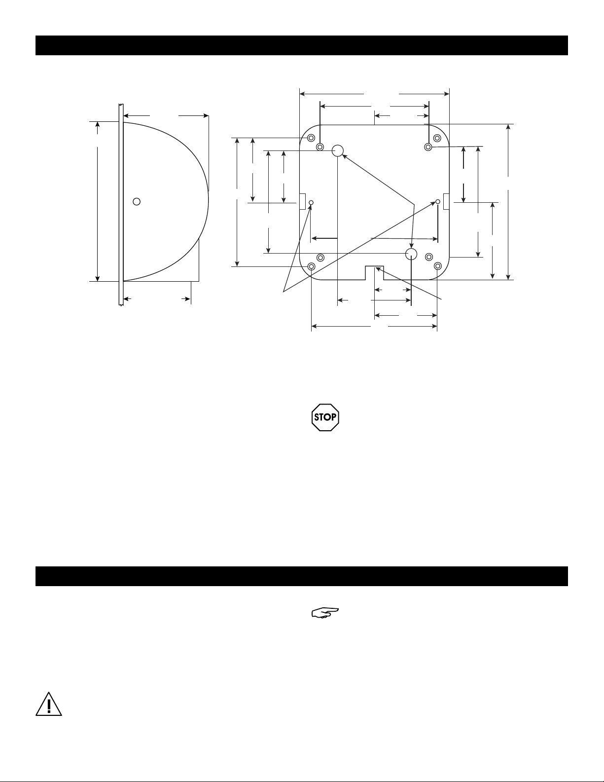
Figure 1

PAGE 2 OF 3 0414 IH-1927
5. Attach base plate at the four corners to smooth wall
(remove control assembly to access the right side
mounting hole). For most secure installation, use two
additional mounting holes. (See Figure 2)
6. Connect the 120 V dryer to a dedicated branch
circuit not exceeding 20 Amp.
7. Secure electrical wiring to terminals as indicated by
the schematic affixed to blower housing. An identified
ground connection point is supplied on the base
plate for the equipment ground wire.
8. Carefully replace cover using the two screws removed
in Step 2. Restore power and test for proper operation.
In multiple installations, make sure the serial number
marked on the inside matches the cover number.
9. Apply a bead of silicone sealant around the
outside of the cover at the wall to protect the dryer
from internal corrosion caused by wash water and
cleaning solutions.
WARNING! To reduce the risk of fire, electric
shock or injury, use dryer only in the manner
intended by the manufacturer.
Before servicing or cleaning unit, switch off
power at service panel and lock the service
disconnecting means to prevent power from
being switched on accidentally.
When the service disconnecting means
cannot be locked, securely fasten a prominent
warning device, such as a tag, to the service
panel.
INSTALLATION CONTINUED
MAINTENANCE
6⁄"
12⁄"
4½"
to center of
air outlet
WALL
SIDE VIEW FRONT VIEW FACING WALL
Location of additional
mounting holes for
more secure installation
Electrical Inlets
(2) 7/8" Dia. Holes
For In-Wall Connection
Surface Mounted
Electrical Entrance
7/8" Dia. Hole
11⁄"
8¼"
4⁄"
(10) Mounting Holes
5/16" Dia.
9½"
5⁄"
2⁄"
9⁄"
4¾"
10⁄"
8⁄"
4⁄"
5⁄"
6⁄"
12⁄"
8¾"
4⁄"
Figure 2
OUTSIDE
Using a soft cloth or sponge and mild soap or detergent,
gently wash the cover (including air inlet holes) with
lukewarm water to loosen dirt and grime.
INSIDE
CAUTION! Shut off power to the dryer at the
service connection. Cleaning should be
performed by qualified service personnel.
NOTE: With normal use, the dryer will require
cleaning once a year. Heavier usage requires
more frequent cleaning. Lint on the air inlet or
other internal parts of dryer will reduce efficiency
and shorten the life of the working parts.
1. Using the tamperproof wrench provided, remove the
cover by unscrewing the two tamperproof bolts from
the side of the cover.
2. Use a small, soft brush to gently clean all parts.

PAGE 3 OF 3 0414 IH-1927
TROUBLESHOOTING
Dryer does not turn on 1. Check power to unit and connections. Verify dryer is receiving voltage at terminal block.
2. Check RED service LED light for the following:
A. Light is ON: Place hands under sensor. If light stays on, then replace sensor. If light goes off, check
to make sure wiring is correct at dryer control. If OK, check motor fuse, if so equipped, and wire
connecting to motor. If both are OK, replace motor.
B. Light is OFF: Check for loose, disconnected or improper wiring at dryer control (see wiring
schematic affixed to blower housing) or replace dryer control.
C. Light is FLASHING: Dryer is in lockout mode (adjust sensor range):
•Ifdryerwillnotturnon,stayson,orstopsworking,itmaybemounted
too close to a counter or object and has gone into lockout.
•Ifrelocatingapplianceisnotpossible,adjusttherangeofthesensorbyturningoffpowerto
dryer. Then turn the range adjustment on the control board counterclockwise towards L (-) low to
decrease sensor range.
Dryer does not shut off May be mounted too close to a counter or object (adjust sensor range, see above).
Check for loose, disconnected or improper wiring at dryer control (refer to wiring schematic affixed to
blower housing).
Replace dryer control.
Dryer heats up but no air comes out Check motor fuse if so equipped.
Check wire connection to motor.
Replace motor.
Dryer does not always turn on
or turns on by itself
May be mounted too close to counter or object (adjust sensor range, see above).
Check for foreign material on optical sensor next to air outlet.
Check for loose wires on dryer control.
Replace dryer control.
Dryer blows only cold air Check for loose connections to heating element.
Replace heating element.
Dryer has a loss of air volume Check for air leaks in the housing or nozzle. If detected, replace housing or nozzle.
Check for slow running motor or burning smell. If so, replace motor.
πCHICAGO•ATLANTA•DALLAS•LOSANGELES•MINNEAPOLIS•NYC/PHILA•SEATTLE•MEXICO•CANADA
1-800-295-5510
uline.com
Other manuals for H-1927
1
This manual suits for next models
2
Other U-Line Dryer manuals