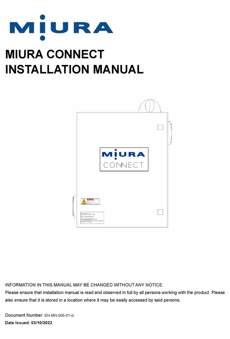
U.S. Boiler Company SteamMax STMX100 User manual

111299-06 - 9/22
SteamMax KA, KS & Kl Boilers
Models:
•STMX100
•STMX125
•STMX150
•STMX175
WARNING
This boiler must only be installed, serviced, and repaired by a qualified installer, service agency or gas
supplier. Improper installation, adjustment, alteration, service or maintenance can cause severe personal
injury, death, or substantial property damage. For assistance or additional information, consult a qualified
installer, service agency or gas supplier. Read these instruction carefully before installing.
!
Knock-Down Boiler Assembly
•STMX200
•STMX250
•STMX299
•STMX350
•STMX399
•STMX450
•STMX500
•STMX550
WARNING
Attention Installer - Affix these instructions
adjacent to boiler. Provide model number and
serial number when seeking information and
support.
Attention Building Owner - Retain these
instructions for future reference. Contact a
qualified installer, service agency or gas
supplier for all issues and support.
!
• Steam Boiler
• Cast Iron
• Chimney Vent
• Gas Fired
Instruction Contents Page
1. Qualified Installer, Service Agency or Gas Supplier
Read Before Proceeding .......................3
2. Parts Check List .............................4
3. Single Base and Section Assembly ............10
4. Split Bases Assembly ........................11
5. Split Section and Base Assembly ..............13
6. Individual Sections Assembly .................16
7. Hydro-Test .................................20
8. Single Canopy Assembly .....................21
9. Dual Canopy Assembly.......................22
10. Single Jacket Assembly ......................23
11. Dual Jacket Assembly ........................25
12. Controls Assembly ..........................28
13. Wiring .....................................29
14. Label Locations .............................38
NOTICE: These assembly procedures should be
used in conjunction with Installation, Operating
and Service Instructions provided with boiler or
available on manufacturer's website.
QR code links to a video
illustrating split-base and
block assembly.
WARNING
Video must be used in conjunction with this
Knock-down Boiler Assembly manual. REVIEW
all notices, cautions and warnings before
assembling boiler.
!

2111299-06 - 9/22
SteamMax Knock-Down Assembly Instructions
The following terms are used throughout this manual to bring attention to the presence of hazards of various
risk levels, or to important information concerning product life.
Massachusetts Board of Plumbers and Gas Fitters has listed SteamMax Boilers. See Massachusetts Board of
Plumbers and Gas Fitters website for latest Approval Code or ask your local Sales Representative.
Commonwealth of Massachusetts requires this product to be installed by a licensed Plumber or Gas fitter.
NOTICE: Indicates special instructions on
installation, operation, or service which are
important but not related to personal injury
hazards.
DANGER
Indicates a hazardous situation that, if not
avoided, will result in death or serious injury.
CAUTION
Indicates a hazardous situation that, if not
avoided, could result in minor or moderate
injury.
WARNING
Indicates a hazardous situation that, if not
avoided, could result in death or serious injury.
! !
!
Important Definitions of Warnings
DANGER
Explosion Hazard. DO NOT store or use gasoline or other flammable vapors or liquids in the vicinity of
this or any other appliance.
If you smell gas vapors, DO NOT try to operate any appliance - DO NOT touch any electrical switch or
use any phone in building. Immediately, call gas supplier from a remotely located phone.
Follow gas supplier’s instructions or if the supplier is unavailable, contact fire department.
WARNING
This boiler must only be serviced and repaired by a qualified installer, service agency or gas supplier.
• If any controls are replaced, they must be replaced with identical models.
• Read, understand and follow all instructions and warnings contained in all sections of this
manual.
• If any electrical wires are disconnected during service, clearly label wires and assure that wires
are reconnected properly.
• Never jump out or bypass any operating control or component of this boiler.
• Assure that all operating controls and components are operating properly before placing
boiler back in service.
• Inspect boiler annually.
!
!

3111299-06 - 9/22
SteamMax Knock-Down Assembly Instructions
WARNING
Asphyxiation Hazard, Burn Hazard, Electrical
Shock Hazard.
• Carefully read all instructions in literature
packet and posted on boiler before attempting
installation, startup, or service of this boiler.
Perform steps in order given. Failure to follow
all instructions in proper order could result in
severe personal injury, death or substantial
property damage.
• Use proper personal protective equipment
when installing, servicing, or working near this
boiler. Materials of construction, flue products,
and fuel contain alumina, silica, heavy metals,
carbon monoxide, nitrogen oxides, and/or
other toxic or harmful substances that can be
hazardous to health and life and that are known
to the State of California to cause cancer, birth
defects, and other reproductive harm.
• Do not disconnect pipe fittings on boiler or
in heating system without first verifying system
is cool and free of pressure and that your
clothing will protect you from a release of hot
water or steam. Do not rely solely on boiler
temperature and pressure gauge when making
this judgement.
• Install all guards, cover plates, and
enclosures before leaving boiler in operation.
• Disconnect electrical supply before installing
or performing maintenance.
• Do not install above 2,000 ft.
• Not for use with LP gas.
!NOTICE:
1. Size boiler properly. A grossly oversized boiler
will cycle excessively leading to premature
failure of boiler and its components. Warranty
does not cover damage from excessive
cycling.
2. Systems employing baseboard and/or
radiators, use an industry accepted
sizing method such as the I=B=R "Residential
Hydronic Heating Installation and Design"
guide published by the Air Conditioning,
Heating and Refrigeration Institute (AHRI).
3. Inspect shipment carefully for signs of
damage. See Tables 2-1 through 2-6 for parts
to build knock-down boilers. Any claim
for damage or shortage in shipment
must be filed immediately against carrier
by consignee. No claims for variances
or shortages will be allowed by boiler
manufacturer, unless presented within 60
days after receipt of equipment.
1Qualified Installer, Service Agency or Gas Supplier Read Before Proceeding
DANGER
• Use precautions and appropriate rigging
apparatus when moving heavy objects.
• Use proper Personal Protective Equipment (PPE)
during assembly.
!

4111299-06 - 9/22
SteamMax Knock-Down Assembly Instructions
2Parts Check List
Table 2-1: Knock-Down Boilers with Assembled Sections and Single Base
Description
Part Number [Quantity]
STMX100 STMX125 STMX150 STMX175 STMX200 STMX250 STMX299
Base Assembly
(BBMA)
110901-03
[1]
110901-04
[1]
110901-04
[1]
110901-05
[1]
110901-05
[1]
110901-06
[1]
110901-07
[1]
Section Assembly 110168-03
[1]
110168-04
[1]
110168-04
[1]
110168-05
[1]
110168-05
[1]
110168-06
[1]
110168-07
[1]
Canopy Carton 110899-03
[1]
110899-04
[1]
110899-04
[1]
110899-05
[1]
110899-05
[1]
110899-06
[1]
110899-07
[1]
Jacket Carton 110898-03
[1]
110898-04
[1]
110898-04
[1]
110898-05
[1]
110898-05
[1]
110898-06
[1]
110898-07
[1]
Draft Hood Carton 110900-03
[1]
110900-04
[1]
110900-04
[1]
110900-05
[1]
110900-05
[1]
110900-06
[1]
110900-07
[1]
Parts Carton - M & M1110903-01
[1]
110903-01
[1]
110903-01
[1]
110903-01
[1]
110903-01
[1]
110903-01
[1]
110903-01
[1]
Parts Carton -
HydroLevel1
110904-01
[1]
110904-01
[1]
110904-01
[1]
110904-01
[1]
110904-01
[1]
110904-01
[1]
110904-01
[1]
Trim Carton 110905-01
[1]
110905-01
[1]
110905-01
[1]
110905-01
[1]
110905-01
[1]
110905-01
[1]
110905-01
[1]
Label Carton 111234-03
[1]
111235-04
[1]
111234-04
[1]
111235-05
[1]
111234-05
[1]
111234-06
[1]
111234-07
[1]
Vent Damper 102284-02
[1]
102284-03
[1]
102284-03
[1]
102284-04
[1]
102284-04
[1]
102284-05
[1]
102284-05
[1]
1One parts carton provided, either McDonnell & Miller or Hydrolevel

5111299-06 - 9/22
SteamMax Knock-Down Assembly Instructions
2Parts Check List (continued)
Description
Part Number [Quantity]
STMX350 STMX399 STMX450 STMX500 STMX550
Split Left Base Assembly (BBMA) 110908-04
[1]
110908-04
[1]
111236-05
[1]
111236-06
[1]
111236-06
[1]
Split Right Base Assembly (BBMA) 110909-04
[1]
110909-05
[1]
111237-05
[1]
111237-05
[1]
111237-06
[1]
Split Left Section Assembly 110169-04
[1]
110169-04
[1]
110169-05
[1]
110169-06
[1]
110169-06
[1]
Split Right Section Assembly 110170-04
[1]
110170-05
[1]
110170-05
[1]
110170-05
[1]
110170-06
[1]
Draw-Up Carton 111239-01
[1]
111239-01
[1]
111239-01
[1]
111239-01
[1]
111239-01
[1]
Canopy Carton
110899-04
[1]
110899-04
[1]
110899-05
[1] 110899-06
[2]
110899-06
[1]
110899-05
[1]
110899-06
[1]
110899-06
[1]
110899-07
[1]
Split Left Jacket Carton 110906-04
[1]
110906-04
[1]
110906-05
[1]
110906-06
[1]
110906-06
[1]
Split Right Jacket Carton 110907-04
[1]
110907-05
[1]
110907-05
[1]
110907-05
[1]
110907-06
[1]
Draft Hood Carton
110900-04
[1]
110900-04
[1]
110900-05
[1] 110900-06
[2]
110900-06
[1]
110900-05
[1]
110900-06
[1]
110900-06
[1]
110900-07
[1]
Parts Carton - M & M1110903-02
[1]
110903-02
[1]
110903-02
[1]
110903-02
[1]
110903-02
[1]
Parts Carton HydroLevel1110904-02
[1]
110904-02
[1]
110904-02
[1]
110904-02
[1]
110904-02
[1]
Trim Carton 110905-03
[1]
110905-02
[1]
110905-02
[1]
110905-02
[1]
110905-02
[1]
Label Carton 111234-08
[1]
111234-09
[1]
111234-10
[1]
111234-11
[1]
111234-12
[1]
1One parts carton provided, either McDonnell & Miller or Hydrolevel
Table 2-2: Knock-Down Boilers with Split Sections and Split Base, NON CSD-1

6111299-06 - 9/22
SteamMax Knock-Down Assembly Instructions
Table 2-3: Knock-Down Boilers with Split Sections and Split Base, CSD-1
Description
Part Number [Quantity]
STMX450 STMX500 STMX550
Split Left Base Assembly (BBMA) 111236-05
[1]
111236-06
[1]
111236-06
[1]
Split Right Base Assembly (BBMA) 111237-05
[1]
111237-05
[1]
111237-06
[1]
Split Left Section Assembly 110169-05
[1]
110169-06
[1]
110169-06
[1]
Split Right Section Assembly 110170-05
[1]
110170-05
[1]
110170-06
[1]
Draw-Up Carton 111239-01
[1]
111239-01
[1]
111239-01
[1]
Canopy Carton
110899-05
[1] 110899-06
[2]
110899-06
[1]
110899-06
[1]
110899-07
[1]
Split Left Jacket Carton 110906-05
[1]
110906-06
[1]
110906-06
[1]
Split Right Jacket Carton 110907-05
[1]
110907-05
[1]
110907-06
[1]
Draft Hood Carton
110900-05
[1] 110900-06
[2]
110900-06
[1]
110900-06
[1]
110900-07
[1]
Parts Carton - M & M1110918-01
[1]
110918-01
[1]
110918-01
[1]
Parts Carton - HydroLevel1110919-01
[1]
110919-01
[1]
110919-01
[1]
Trim Carton 110905-02
[1]
110905-02
[1]
110905-02
[1]
Label Carton 111234-10
[1]
111234-11
[1]
111234-12
[1]
2Parts Check List (continued)
1One parts carton provided, either McDonnell & Miller or Hydrolevel

7111299-06 - 9/22
SteamMax Knock-Down Assembly Instructions
Table 2-4: Knock-Down Boilers with Individual Sections and Single Base
Description
Part Number [Quantity]
STMX100 STMX125 STMX150 STMX175 STMX200 STMX250 STMX299
Base Assembly (BBMA) 110901-03
[1]
110901-04
[1]
110901-04
[1]
110901-05
[1]
110901-05
[1]
110901-06
[1]
110901-07
[1]
Left End Section 110166-01
[1]
110166-01
[1]
110166-01
[1]
110166-01
[1]
110166-01
[1]
110166-01
[1]
110166-01
[1]
Right End Section 110167-01
[1]
110167-01
[1]
110167-01
[1]
110167-01
[1]
110167-01
[1]
110167-01
[1]
110167-01
[1]
Intermediate Section with Riser 110165-01
[1]
110165-01
[1]
110165-01
[1]
110165-01
[2]
110165-01
[2]
110165-01
[2]
110165-01
[2]
Intermediate Section without Riser N/A 110164-01
[1]
110164-01
[1]
110164-01
[1]
110164-01
[1]
110164-01
[2]
110164-01
[3]
Draw-Up Carton 111238-03
[1]
111238-04
[1]
111238-04
[1]
111238-05
[1]
111238-05
[1]
111238-06
[1]
111238-07
[1]
Tie Rod Bundle 111364-03
[1]
111364-04
[1]
111364-04
[1]
111364-05
[1]
111364-05
[1]
111364-06
[1]
111364-07
[1]
Canopy Carton 110899-03
[1]
110899-04
[1]
110899-04
[1]
110899-05
[1]
110899-05
[1]
110899-06
[1]
110899-07
[1]
Jacket Carton 110898-03
[1]
110898-04
[1]
110898-04
[1]
110898-05
[1]
110898-05
[1]
110898-06
[1]
110898-07
[1]
Draft Hood Carton 110900-03
[1]
110900-04
[1]
110900-04
[1]
110900-05
[1]
110900-05
[1]
110900-06
[1]
100900-07
[1]
Parts Carton - M & M1110903-01
[1]
110903-01
[1]
110903-01
[1]
110903-01
[1]
110903-01
[1]
110903-01
[1]
110903-01
[1]
Parts Carton - HydroLevel1110904-01
[1]
110904-01
[1]
110904-01
[1]
110904-01
[1]
110904-01
[1]
110904-01
[1]
110904-01
[1]
Trim Carton 110905-03
[1]
110905-03
[1]
110905-03
[1]
110905-01
[1]
110905-03
[1]
110905-03
[1]
110905-03
[1]
Label Carton 111234-03
[1]
111235-04
[1]
111234-04
[1]
111235-05
[1]
111234-05
[1]
111234-06
[1]
111234-07
[1]
Vent Damper 102284-02
[1]
102284-03
[1]
102284-03
[1]
102284-04
[1]
102284-04
[1]
102284-05
[1]
102284-05
[1]
1One parts carton provided, either McDonnell & Miller or Hydrolevel
2Parts Check List (continued)

8111299-06 - 9/22
SteamMax Knock-Down Assembly Instructions
Description
Part Number [Quantity]
STMX350 STMX399 STMX450 STMX500 STMX550
Split Left Base Assembly (BBMA) 110908-04
[1]
110908-04
[1]
111236-05
[1]
111236-06
[1]
111236-06
[1]
Split Right Base Assembly (BBMA) 110909-04
[1]
110909-05
[1]
111237-05
[1]
111237-05
[1]
111237-06
[1]
Left End Section 110166-01
[1]
110166-01
[1]
110166-01
[1]
110166-01
[1]
110166-01
[1]
Right End Section Assembly 110167-01
[1]
110167-01
[1]
110167-01
[1]
110167-01
[1]
110167-01
[1]
Intermediate Section with Riser 110165-01
[3]
110165-01
[3]
110165-01
[4]
110165-01
[4]
110165-01
[4]
Intermediate Section without Riser 110164-01
[3]
110164-01
[4]
110164-01
[4]
110164-01
[5]
110164-01
[6]
Draw-Up Carton 111238-08
[1]
111238-09
[1]
111238-10
[1]
111238-11
[1]
111238-12
[1]
Tie Rod Bundle 111364-08
[1]
111364-09
[1]
111364-10
[1]
111364-11
[1]
111364-12
[1]
Canopy Carton
110899-04
[1]
110899-04
[1]
110899-05
[1] 110899-06
[2]
110899-06
[1]
110899-05
[1]
110899-06
[1]
110899-06
[1]
110899-07
[1]
Split Left Jacket Carton 110906-04
[1]
110906-04
[1]
110906-05
[1]
110906-06
[1]
110906-06
[1]
Split Right Jacket Carton 110907-04
[1]
110907-05
[1]
110907-05
[1]
110907-05
[1]
110907-06
[1]
Draft Hood Carton
110900-04
[1]
110900-04
[1]
110900-05
[1] 110900-06
[2]
110900-06
[1]
110900-05
[1]
110900-06
[1]
110900-06
[1]
110900-07
[1]
Parts Carton - M & M1110903-02
[1]
110903-02
[1]
110903-02
[1]
110903-02
[1]
110903-02
[1]
Parts Carton - HydroLevel1110904-02
[1]
110904-02
[1]
110904-02
[1]
110904-02
[1]
110904-02
[1]
Trim Carton 110905-03
[1]
110905-02
[1]
110905-02
[1]
110905-02
[1]
110905-02
[1]
Label Carton 111234-08
[1]
111234-09
[1]
111234-10
[1]
111234-11
[1]
111234-12
[1]
1One parts carton provided, either McDonnell & Miller or Hydrolevel
Table 2-5 Knock-Down Boilers with Individual Sections and Split Base, NON CSD-1
2Parts Check List (continued)

9111299-06 - 9/22
SteamMax Knock-Down Assembly Instructions
Table 2-6: Knock-Down Boilers with Individual Sections and Split Base, CSD-1
Description
Part Number [Quantity]
STMX450 STMX500 STMX550
Split Left Base Assembly (BBMA) 111236-05 [1] 111236-06 [1] 111236-06 [1]
Split Right Base Assembly (BBMA) 111237-05 [1] 111237-05 [1] 111237-06 [1]
Left End Section 110166-01 [1] 110166-01 [1] 110166-01 [1]
Right End Section 110167-01 [1] 110167-01 [1] 110167-01 [1]
Intermediate Section with Riser 110165-01 [4] 110165-01 [4] 110165-01 [4]
Intermediate Section without Riser 110164-01 [4] 110164-01 [5] 110164-01 [6]
Draw-Up Carton 111238-10 [1] 111238-11 [1] 111238-12 [1]
Tie Rod Bundle 111364-10 [1] 111364-11 [1] 111364-12 [1]
Canopy Carton 110899-05 [1] 110899-06 [2] 110899-06 [1]
110899-06 [1] 110899-07 [1]
Split Left Jacket Carton 110906-05 [1] 110906-06 [1] 110906-06 [1]
Split Right Jacket Carton 110907-05 [1] 110907-05 [1] 110907-06 [1]
Draft Hood Carton 110900-05 [1] 110900-06 [2] 110900-06 [1]
110900-06 [1] 110900-07 [1]
Parts Carton - M & M1110918-01 [1] 110918-01 [1] 110918-01 [1]
Parts Carton - Hydrolevel1110919-01 [1]
Trim Carton 110905-02 [1] 110905-02 [1] 110905-02 [1]
Label Carton 111234-10 [1] 111234-11 [1] 111234-12 [1]
1One parts carton provided, either McDonnell & Miller or Hydrolevel
2Parts Check List (continued)
Table 2-7: Knock-Down Boilers Bare Block Assembly Dimensions
# of sections (split or assembled) Width (in.) Height (in.) Depth (in.) Weight (lbs.)
3 15-1/2 20-1/2 20 295
4 20-1/2 20-1/2 20 390
5 25-1/2 20-1/2 20 485
6 30-1/2 20-1/2 20 580
7 35-1/2 20-1/2 20 675
Individual sections are 5 in. wide x 20-1/2 in. high x 20 in. deep and 98 pounds.

10 111299-06 - 9/22
SteamMax Knock-Down Assembly Instructions
DANGER
• Use precautions and appropriate rigging
apparatus when moving heavy objects.
• Use proper personal protective equipment (PPE)
during assembly.
3Single Base and Section Assembly
See Figures 3-1 and 3-2 for References.
1. Remove base assembly, Item 1, from shipping
skid.
2. Place base assembly in location where boiler is to
be installed.
A. Appliance is listed for installation on
combustible flooring and must not be
installed on carpeting.
Figure 3-1: Base and Section Assembly
B. Install on level floor. For basement installation
provide concrete base if floor is not level or if
water may be encountered on floor around
boiler.
C. Protect gas ignition system components
from water (dripping, spraying, etc.) during
appliance operation and service.
D. Locate boiler to avoid water damage in case
there is a leak. If boiler must be located in an
area sensitive to water damage, install drain
pan underneath boiler and pipe to a suitable
drain location. Manufacturer will not be held
responsible for water damage resulting from
this appliance or any of its components.
3. Set aside rear air dam, not shown. Air dam will be
installed after jacket attachment.
4. Verify the (4) drip shields, Item 2, are in place,
and remove tape used to hold the drip shields in
place during shipment.
5. Screw (2) 5/16-18 hex head bolts, Item 3, into
holes in both side of base assembly.
6. Install refractory ceramic fiber gasket, Item 4,
onto base assembly.
7. Lower section assembly, Item 5, onto base
assembly. Center bolts in slots on both sides of
section assembly.
8. Tighten 5/16-18 nylon locking nuts and washers,
Item 6, onto bolts.
9. Hydrostatically test each section assembly.
NOTICE: It is essential that hydrostatic testing
be done before canopy, jacket, controls or piping
is installed. See Hydro-Test Section for procedure.
!
Figure 3-2: Knock-Down Hardware Detail
66
4
3
1
5
22
6
3
6

11111299-06 - 9/22
SteamMax Knock-Down Assembly Instructions
DANGER
• Use precautions and appropriate rigging
apparatus when moving heavy objects.
• Use proper personal protective equipment (PPE)
during assembly.
4Split Bases Assembly
See Figure 4-1 for References.
1. Remove split base assemblies, Items 1 and 2,
from shipping skids.
2. Move base assemblies to area where boiler is to
be installed.
A. Appliance is listed for installation on
combustible flooring and must not be
installed on carpeting.
B. Install on level floor. For basement installation
provide concrete base if floor is not level or if
water may be encountered on floor around
boiler.
C. Protect gas ignition system components
from water (dripping, spraying, etc.) during
appliance operation and service.
D. Locate boiler to avoid water damage in case
there is a leak. If boiler must be located in an
area sensitive to water damage, install drain
pan underneath boiler and pipe to a suitable
drain location. Manufacturer will not be held
responsible for water damage resulting from
this appliance or any of its components.
3. Set aside rear air dams, not shown. Air dams will
be installed after jacket attachment.
4. Set aside jacket top bracket, not shown, packed
with split left base assembly. Bracket will be
attached after split section assemblies are drawn.
NOTICE: No gasket material is required between
the two bases.
5. Verify the (6) drip shields, Item 3, are in place,
and remove tape used to hold the drip shields in
place during shipment.
6. Use ¼-20 hex head bolts and nuts, Item 4, to join
split base assemblies together with jacket lower
bracket, Item 5, attached on left side.
7. Attach base legs, Item 6, to base assembly using
¼-20 self-threading screws, Item 7.
8. Place base assembly in location where boiler is to
be installed.
!

12 111299-06 - 9/22
SteamMax Knock-Down Assembly Instructions
4Split Bases Assembly (continued)
Figure 4-1: Split Bases Assembly
1
2
5
4
4
33
7 6
44

13111299-06 - 9/22
SteamMax Knock-Down Assembly Instructions
DANGER
• Use precautions and appropriate rigging
apparatus when moving heavy objects.
• Use proper Personal Protective Equipment (PPE)
during assembly.
5Split Section and Base Assembly
See Figures 5-1, 5-2, 5-3 and 3-2 for References.
1. Either left section assembly or right section
assembly can be secured first. Left section
assembly will be secured first for purposes of this
instruction.
NOTICE: Insulation between base and section
assembly is not used. A high temperature silicone
RTV will be used to seal base/section assembly
joint after section assemblies are joined on base.
See step 19.
2. Screw (2) 5/16-18 hex head bolts, Item 1, into
holes in base.
3. Lower left assembly, Item 2, onto base with bolts
centered in assembly slots.
4. Tighten 5/16-18 nylon locking nuts and washers,
Item 3, onto bolts.
5. Thoroughly clean nipples, Item 4, and nipple
ports with a de-greasing solvent.
6. Evenly coat nipples and nipple ports with
provided Loctite® 592.
7. Place nipples in nipple ports and bump carefully
with a wooden block to set.
8. Apply provided SIL-BOND RTV 6500 to flue way
joint. See Figure 5-1.
9. Place right section assembly, Item 5, onto base
as close to left section assembly as possible
aligning nipples to nipple ports.
10. Screw together enough 3/4-10 x 11" draw rod
using coupling nuts, Item 6, to pass through
section assemblies, Items 2 and 5, draw plates,
washers & nuts, Item 7, on both sides. Two draw
rods are required, one through upper nipple port
and other through lower nipple port.
11. Keep draw rod threads lubricated to reduce
friction for easier assembly.
12. Draw section assemblies together slowly and
evenly. Alternately tighten upper and lower draw
rods. Tighten each draw rod a little at a time so
sections are evenly spaced. Either base assembly
and/or section assemblies may require adjusting
to maintain nipple and nipple port alignments.
13. Tighten until sections meet iron-to-iron. Small
gaps, typically less than 1/16", between sections
after assembly are normal.
NOTICE: Do not loosen or remove draw rods until
tie rods are secured.
14. Screw (2) 5/16-18 hex head bolts through base
holes and section assembly slots on right side.
15. Tighten 5/16-18 nylon locking nuts and washers
onto bolts.
16. Place 3/8-16 x 7-3/4" long tie rods, Item 8, through
top lug holes at upper and lower nipple ports.
17. Tighten 3/8-16 nut and washer, Item 9, onto each
end of a tie rod until hand tight. This will allow for
thermal expansion.
18. Remove draw rods.
19. Hydrostatically test section assembly.
NOTICE: It is essential that hydrostatic testing
be done before sealing block to base (step
20) and before canopy, jacket, controls, and
piping are installed. See Hydro-Test Section for
procedure.
20. Apply provided SIL-BOND RTV 6500 to entire
perimeter of base/section assembly joint. See
Figure 5-2.
Flue Way
Joint
Flue Way
Joint
Figure 5-1: Assembly Section Flue Way Joint
Apply Silicone
Here
Apply Silicone
Here
!

14 111299-06 - 9/22
SteamMax Knock-Down Assembly Instructions
5Split Section and Base Assembly (continued)
Figure 5-2: Split Section and Base Assembly
777
7
2
5
Apply silicone
here
Apply silicone
here
Apply silicone
here
33
1

15111299-06 - 9/22
SteamMax Knock-Down Assembly Instructions
5Split Section and Base Assembly (continued)
Figure 5-3: Push Nipple and Tie Rods Detail
4 6
8
99

16 111299-06 - 9/22
SteamMax Knock-Down Assembly Instructions
DANGER
• Use precautions and appropriate rigging
apparatus when moving heavy objects.
• Use proper Personal Protective Equipment (PPE)
during assembly.
6Individual Sections Assembly
See Figures 6-1, 6-2 and 6-3 for References.
1. Clean sections inside and out to remove dirt due
to shipping and handling.
2. Either left end section or right end section can be
positioned first. Left end section will be positioned
first for purposes of this instruction.
NOTICE: Insulation between base and section
assembly is not used. A high temperature silicone
RTV will be used to seal base/section assembly
joint after sections are assembled on base. See
Step 22.
3. Verify the (4) drip shields, Item 1, are in place,
and remove tape used to hold the drip shields in
place during shipment.
4. Screw (2) 5/16-18 hex head bolts, Item 2, into
holes in base.
5. Place left end section, Item 3, onto base with slots
centered on bolts.
6. Tighten 5/16-18 nylon locking nuts and washers,
Item 4, onto bolts.
7. Thoroughly clean nipples, Item 5, and nipple
ports with a de-greasing solvent.
8. Evenly coat nipples and nipple ports with
provided Loctite® 592.
9. Place nipples in nipple ports and bump carefully
with a wooden block to set.
10. Apply provided SIL-BOND RTV 6500 to flue way
joint. See Figure 5-1.
11. Place next section, Item 6, onto base as close to
left end section as possible aligning nipples to
nipple ports.
NOTICE: Refer to Figure 6-3 for proper location
of intermediate section with and without riser
tappings.
12. Screw together enough 3/4-10 x 11" draw rod
using coupling nuts to pass through section
assemblies, Items 3 and 6, draw plates, washers
& nuts, Item 7, on both sides. Two draw rods are
required, one through upper nipple port and other
through lower nipple port.
13. Keep draw rod threads lubricated to reduce
friction which makes assembly easier.
14. Draw section assemblies together slowly and
evenly. Alternately tighten upper and lower draw
rods. Tighten each draw rod a little at a time
so sections are evenly spaced. Either base
assembly and/or section assemblies may require
adjusting to maintain nipple and nipple port
alignments.
15. Tighten until sections meet iron-to-iron. Small
gaps, typically less than 1/16”, between sections
after assembly are normal.
16. Repeat Steps 7 through 15 for remaining sections.
17. Screw (2) 5/16-18 hex head bolts through base
holes and section assembly slots on right side.
18. Tighten 5/16-18 nylon locking nuts and washers
onto bolts.
19. Place 3/8-16 tie rods, Item 8, through top lug
holes at upper and lower nipple ports.
20. Tighten 3/8-16 nut and washer, Item 9, onto each
end of a tie rod until hand tight. This will allow for
thermal expansion.
21. Repeat Steps 19 and 20 for bottom lug holes at
upper and lower nipple ports.
22. Remove draw rods.
23. Hydrostatically test section assembly.
NOTICE: It is essential that hydrostatic testing
be done before sealing block to base (step
24) and before canopy, jacket, controls, and
piping are installed. See Hydro-Test Section for
procedure.
24. Apply provided SIL-BOND RTV 6500 to entire
perimeter of base/section assembly joint. See
Figure 6-2.
!

17111299-06 - 9/22
SteamMax Knock-Down Assembly Instructions
6Individual Sections Assembly (continued)
Figure 6-1: Single Base and Individual Sections
777
6
3
2 44
77
5
11

18 111299-06 - 9/22
SteamMax Knock-Down Assembly Instructions
Figure 6-2: Split Base and Individual Sections
6Individual Sections Assembly (continued)
Apply silicone
here
9
8
Apply silicone
here

19111299-06 - 9/22
SteamMax Knock-Down Assembly Instructions
6Individual Sections Assembly (continued)
Figure 6-3: Arrangement of Sections and Canopies
3 Section 4 Section 5 Section 6 Section
8 Section 9 Section
10 Section
7 Section
11 Section 12 Section
Riser Location

20 111299-06 - 9/22
SteamMax Knock-Down Assembly Instructions
7 Hydro-Test
NOTICE: It is essential that hydrostatic testing be
done before canopy, jacket, controls or piping is
installed.
Hydro-Test per requirements of authority having
jurisdiction. In the absence of such requirements, the
following procedure can be used.
1. Run a hose from water service to one of the
lower tappings.
2. Install a ball or gate valve in one of the
tappings on top of block and connect other
end to a drain.
3. Plug tappings on end sections that will not
be used on final installation with supplied
plugs. Consult Installation, Operating and
Service Instructions supplied with this boiler
or located on manufacturer’s website for size
and purpose of tappings.
NOTICE: Limit controls, LWCOs and junction
box must be installed on same side of boiler.
Otherwise, wiring harness will not fit configuration.
4. Install a pressure gauge in any convenient
tapping.
5. Plug all remaining unused tappings.
6. Fill boiler until a steady stream of water is
flowing down the drain.
7. Slowly close valve until pressure reads
between 40 and 45 psi.
CAUTION
Do not exceed 50 psi. Over pressurizing section
assembly could cause failure.
8. Let boiler stand 5 to 10 minutes.
CAUTION
Do not leave section assembly filled with water
and unattended. Leaks may occur resulting in
substantial property damage.
9. Examine all parts of section assembly for
leaks.
10. Drain boiler.
11. Remove plugs from tappings used on final
installation.
!
!
Figure 8-1: Single Canopy Assembly
This manual suits for next models
11
Table of contents
Other U.S. Boiler Company Boiler Supplies manuals