The Safgard VXT water feeder (available sepa-
rately) is fully programmable to accommodate
any steam system. By simply arranging a series
of rocker switches the delay time before feed
can be adjusted to allow condensate to return to
the boiler. Settings from 30 seconds to ten min-
utes are available. The amount of feed can also
be set from one to five gallons. If necessary, a
second delay/feed cycle is permitted. If the low
water condition still exists after the second cycle
the control will lock-out to prevent flooding of
the system.
VXT WATER FEEDER
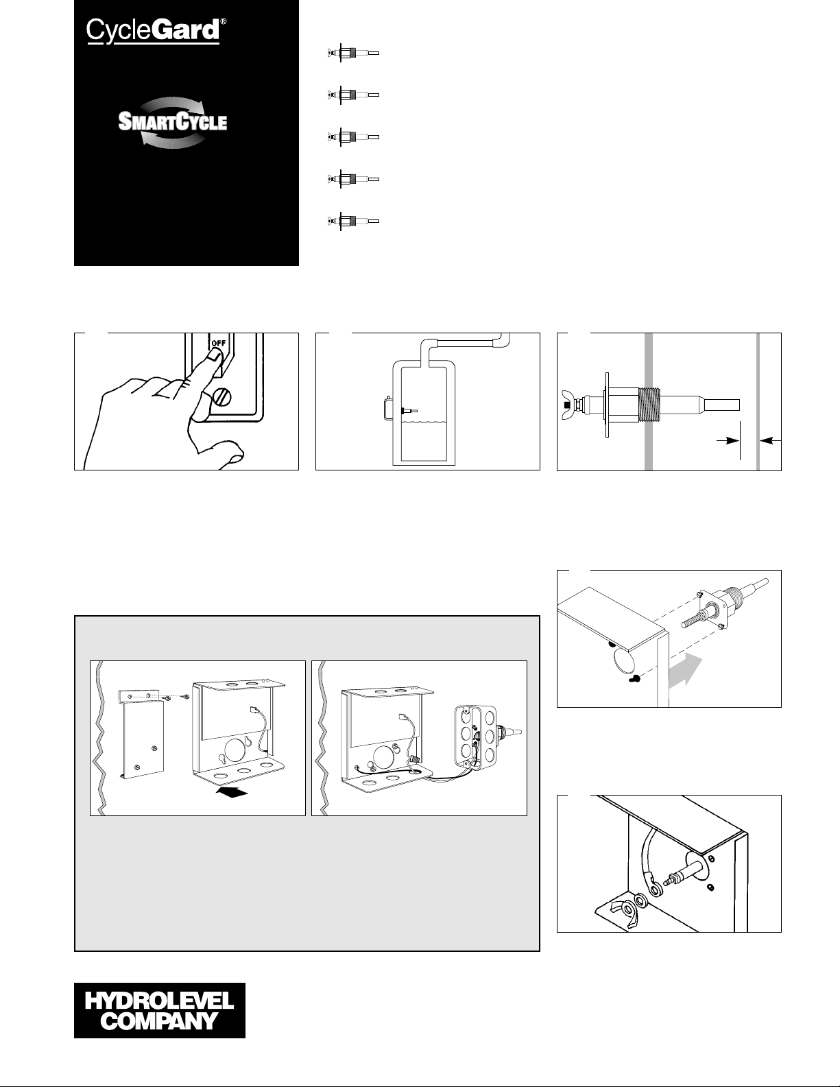
PROBES
Test Pressure: 1000 PSI, All Models
THE PROBE MAKES THE DIFFERENCE
The probe used in all Hydrolevel controls offers
you distinctive advantages. Unlike float devices,
there are no moving parts to wear stick, or
“hang-up” the in harsh boiler environment .
A stuck or “hung-up” float can cause dangerous
low water conditions. And if suddenly released, a
float can feed cold water into overheated tubes
or plates and cause explosive results.
The Hydrolevel control has no float bowl so sed-
iment cannot collect. The reliable solid state cir-
cuitry and low maintenance probe are designed
to provide years of troublefree operation.
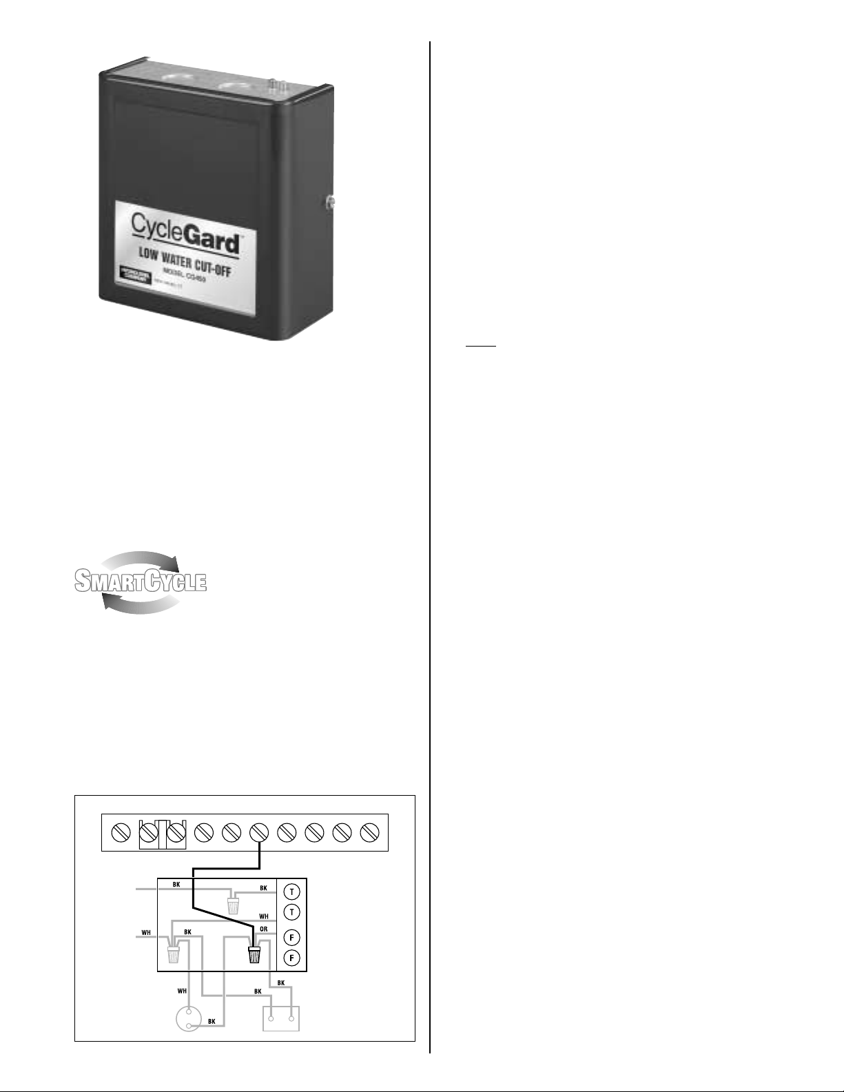
MAXIMUM PRESSURE: 15 PSI
INPUT VOLTAGE: 120 VAC, 60 HZ
SWITCH RATINGS: 5.8 FLA, 34.8 LRA
SWITCH CONTACTS: SPDT
ALARM CIRCUIT: 125 VA @ 120 VAC
Pilot Duty
EL1214 – STANDARD MODEL – 3/4" NPT
For 1/2”, order Model No. EL-1220 EL1214-P – 3/4" NPT
LIMITED MANUFACTURER’S WARRANTY
We warrant products manufactured by
Hydrolevel Company to be free from defects in
material and workmanship for a period of two
years from the date of manufacture or one year
from the date of installation, whichever occurs
first. In the event of any claim under this warran-
ty or otherwise with respect to our products
which is made within such period, we will, at our
option, repair or replace such products or refund
the purchase price paid to us by you for such
products. In no event shall Hydrolevel Company
be liable for any other loss or damage, whether
direct, indirect, incidental or consequential. This
warranty is your EXCLUSIVE remedy and shall be
IN PLACE OF any other warranty or guarantee,
express or implied, including, without limitation,
any warranty of MERCHANTABILITY or fitness
for a particular purpose. This warranty may not
be assigned or transferred and any unauthorized
transfer or assignment thereof shall be void and
of no force or effect.
P.O. Box 1847
New Haven, CT 06508
Phone: (203) 776-0473
FAX: (203) 773-1019