Miura MP1-200 User manual

INSTALLATION
MANUAL
Multiple Installation Controller
Pressure Controller MP1-200
MI Terminal MT1-200
Installation Manual Code No.
T519-998-9140
(E20-036-01)

Date of preparation: May 2012

i
Introduction
This Installation Manual explains the installation of Pressure Controller MP1-200A (hereinafter
called MP1-200) and MI terminal MT1-200 (hereinafter called MT1-200).
For your safety, install MP1-200 and MT1-200 only after you have thoroughly read and
understood the content of this manual. Pay particular attention to the symbols (DANGER,
WARNING, CAUTION, and NOTE) below which are listed in order of their seriousness.
Indicates an imminently dangerous situation which leads to serious injury or
death to the user, if the product is mishandled.
Indicates a situation which might cause serious injury or death to the user, if
the product is mishandled.
Indicates a situation which might cause minor injury to the user or the
occurrence of physical damage only, if the product is mishandled.
Describes the precautions to prevent failures of the boiler, points to perform
effective operation, and useful information to know.
NOTE

Document No. E20-036-01
1
Table of Contents
1. PRECAUTIONS REGARDING INSTALLATION ...................................2
2. OVERALL DIMENSIONS ......................................................................3
2.1. MP1-200 Overall Dimensions..............................................................................3
2.2. MT1-200 Overall Dimensions ..............................................................................4
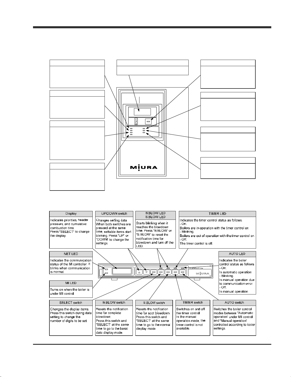
3. COMPONENT NAMES ..........................................................................5
3.1. Components of Display Control Panel.................................................................5
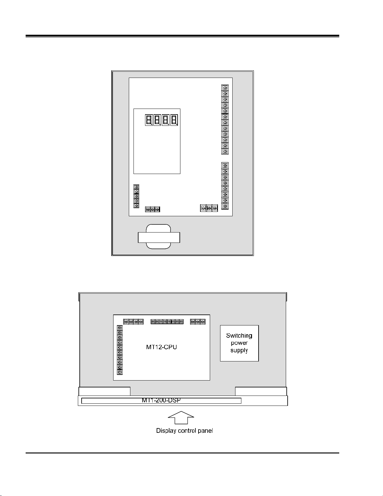
3.2. Internal Circuit Board Layout and Component Names ........................................6
4. PARTS ...................................................................................................7
4.1. Main Unit .............................................................................................................7
4.2. Accessories .........................................................................................................7
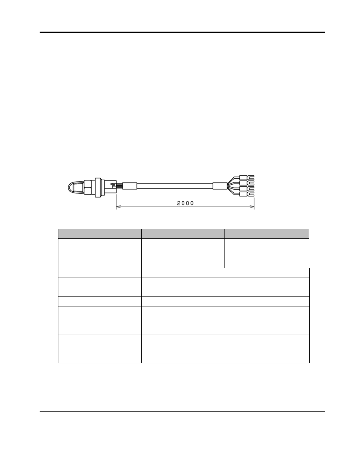
4.2.1. Steam Pressure Sensor ................................................................................ 7
4.3. Parts Required for Installation .............................................................................8
5. INSTALLATION......................................................................................9
5.1. Precautions when Performing Unit Installation ....................................................9
5.2. MP1-200 Installation Procedure ........................................................................10
5.3. MT1-200 Installation Procedure......................................................................... 11
5.4. Precautions when Installing Steam Pressure Sensor ........................................12
6. WIRING ................................................................................................14
6.1. Precautions........................................................................................................14
6.2. Wiring Procedure...............................................................................................15
6.3. Terminal Layout on the Control Board ...............................................................16
6.4. Wires .................................................................................................................17
6.5. Input/Output Signal Wire ...................................................................................18
6.6. MI-NET Communications Wiring .......................................................................21
6.7. Steam Pressure Sensor Wiring .........................................................................22
6.8. Earthquake Detector Wiring ..............................................................................23
7. WIRING EXAMPLE..............................................................................24
7.1. Boiler with XJ Controller Installed ......................................................................24
7.2. Boiler with BL Controller Installed......................................................................25
8. MI NUMBER PLATE ATTACHMENT...................................................26
8.1. Attachment Procedure .......................................................................................26
8.2. Attachment Location ..........................................................................................26

Document No. E20-036-01
2
1. PRECAUTIONS REGARDING INSTALLATION
Pay significant attention to the precautions below when performing installation or instrumentation.
(1) The ground wire must be connected to the ground terminal inside the power panel. The diameter of
the electric wire to be used must be equal to or more than that of the power supply wire.
(2) Do not install any overcurrent circuit breakers to the grounding wire.
(3) Ensure that a dedicated earth leakage circuit breaker (with overcurrent protection) has been
installed when wiring the main power supply from the power panel.
(4) Ensure that the insulation resistance of the main power wire is equal to or more than 0.1 MΩ.
(5) When wiring from the power panel, the wire diameter for power supply must be equal to or more
than 2.0 mm2
(AWG14).When wiring the power supply of MT1-200 from the boiler control panel, the
wire diameter must be equal to or more than 0.9 mm2(AWG18).
(6) Do not extend the steam pressure sensor cable.
(7) Ensure that the distance of communications wiring does not exceed 300 m.
NOTE) Follow all code and local regulations as your instruction .

Document No. E20-036-01
3
2. OVERALL DIMENSIONS
2.1. MP1-200 Overall Dimensions
Specifications
Item Unit MP1-200A
Power supply - 120 VAC
50/60 Hz single phase
Required wire
diameter for power
supply
mm22.0 (AWG14)
Power circuit breaker
capacity A 3
Power consumption VA 11 (At maximum)
Product mass
(product weight)
Kg
(Lb)
3.2
(7.1)
250 52 214 18
4-φ6
(mm)

Document No. E20-036-01
4
2.2. MT1-200 Overall Dimensions
Specifications
Item Unit MT1-200
Power supply - 100 to 220 VAC 50/60 Hz single phase
Required wire
diameter for power
supply
mm22.0 (AWG14)
Power circuit breaker
capacity A 5
Power consumption VA 7 (At maximum)
Product mass
(product weight)
Kg
(Lb)
3.3
(7.3)
5011535
195
23
57
(mm)

Document No. E20-036-01
5
3. COMPONENT NAMES
3.1. Components of Display Control Panel
(a) MP1-200
(b) MT1-200
It turns ON when the steam
pressure becomes the set value
of pressure alarm H or more. At
this time, the contact of pressure
alarm H output turns ON.
HIGH-PRESSURE LED
It turns ON when the steam
pressure becomes the set value
of pressure alarm L or less. At this
time, the contact of pressure
alarm L output turns ON.
LOW-PRESSURE LED
It turns ON when the circuit
between external control input
terminals 2 and 3 is shorted. At
this time, the boilers that are
under normal communication
conditions are stopped regardless
of pressure and manual/automatic
mode.
EMERGENCY STOP LED
It turns ON when the circuit
between external control input
terminals 7 and 8 (all stop) or
between 6 and 7 (all combustion)
is shorted.
LUMP OPERATION LED
It is used to change the display
items on the 4-digit LED.
When the external output “alarm”
is ON, press it. The output turns
OFF.
DISPLAY CHANGE switch
It turns ON if any of the buzzers
for the boilers under MI control is
activated.
At this time, the external output
“boiler trouble” turns ON.
BOILER TROUBLE LED
It turns ON if an abnormality of
pressure sensor is detected. At
this time, the external output
“sensor fail” turns ON.
SENSOR FAIL LED
It turns ON if the CPU is not
correctly operated due to voltage
fluctuation, circuit failure, etc.
CPU FAIL LED
MI-TERMINAL
PRESSURE
CONTROLLER
MP1-200
It displays the steam pressure and other
settings.
Display

Document No. E20-036-01
6
3.2. Internal Circuit Board Layout and Component Names
(a) MP1-200
Figure 3-1 MP1-200 Internal Circuit Board Layout and Component Names
(b) MT1-200
Figure 3-2 MT1-200 Internal Circuit Board Layout and Component Names
Transformer
MP1-200
CPU
MP1-200
DSP

Document No. E20-036-01
7
4. PARTS
4.1. Main Unit
Ensure beforehand that the power supply voltage to be used for MP1-200 is compatible.
4.2. Accessories
The included Package Content Booklet lists accessories for MP1-200 and MT1-200.
Refer to the Package Content Booklet, and check the accessories for any damage.
Contact a MIURA sales office to inquire about defective products or others.
4.2.1. Steam Pressure Sensor
Depending on the pressure specifications, MP1-200 includes one of the following steam pressure
sensors.
Steam pressure sensors for MT1-200 are optionally available and must be arranged separately.
Pressure specifications 0.98 MPa 1.96 MPa
Model YSK-AC10M-333 YSK-AC20M-334
Pressure range 0 to 0.98 MPa
(0 to 142 PSI)
0 to 1.96 MPa
(0 to 284 PSI)
Power supply voltage 10.5 to 28 VDC
Operating temperature range -20 to 80°C
Connection R1/4
Moisture/Water resistance JIS D0203 S2
Output 1 to 5 VDC
Material Diaphragm: SUS316L
Connection: C3604
General accuracy
at 1013 hPa
±3%FS (-20 to 70°C)
±4%FS (70 to 80°C)
±5%FS (80 to 90°C)
Gray: Shield
Black: Power supply ground
White: Voltage output
Red: Power supply+
mm

Document No. E20-036-01
8
4.3. Parts Required for Installation
The following parts are required for the installation of MP1-200 and MT1-200. Ensure that you have the
required parts before installation.
(a) MP1-200
Prepare screws to install MP1-200 (M5 or equivalent recommended)

Document No. E20-036-01
9
5. INSTALLATION
5.1. Precautions when Performing Unit Installation
Install the unit in the prescribed operating environment including the temperature and humidity
ranges.
Do not perform installation in any of the following locations as failure of the unit may occur.
(1) In direct sunlight or near appliances that generate heat.
(2) Places where temperature is high and/or where there are intense fluctuations in temperature.
(3) Places where moisture is high and where dust collects.
(4) Places that are subject to shocks or vibrations.
(5) In an atmosphere of chemicals, places where the unit may be exposed to chemicals, and/or
places where the unit may come into contact with water.
(6) Places where there are transmission wires or there is anything that emits a strong magnetic
force.
(7) Places where there are intense fluctuations in power-supply voltage.
Secure MP1-200 and MT1-200 in places that are not subject to vibrations.
Install in places where there is no steam or water resulting from condensation. Ensure that there is
no condensed dew running down the steam pipes and coming into contact with MP1-200 and
MT1-200.
When performing installation, do not touch the circuit board on the inside of the unit. Ensure that no
dust, pieces of metal or anything else enters the inside of the MP1-200 and MT1-200 units.
Install MP1-200 and MT1-200 so that the wiring distance to the steam pressure sensor does not
exceed 2 m. Steam pressure sensors are optional for MT1-200.
MP1-200 and MT1-200 are designed for use indoors. When performing installation outdoors, ensure
that the installation area is free of exposure to direct sunlight and that precautions have been taken
against water, dust and freezing.
Do not weld MP1-200 and MT1-200 directly to a pole or wall. Since they are
equipped with built-in electronic devices, arc welding may cause failure of
such devices.
Be sure to observe the following precautions about installation.
Ensure that the unit has been installed in the prescribed location.
Improper installation may cause failures of the equipment used.

Document No. E20-036-01
10
5.2. MP1-200 Installation Procedure
Install MP1-200 according to the procedure below.
(1) Bore screw holes on the area designated for MP1-200 to be secured.
Installation dimensions: 280 mm x 214 mm (Refer to “2.1. MP1-200 Overall Dimensions”.)
(2) Open the front panel of MP1-200.
(3) Secure the base plate of MP1-200 with the screws (M5 or equivalent recommended). (Refer to
“4.3.1. MP1-200 Required Parts”.)
Note Allow 100 mm or more of space on the left, right and upper parts for maintenance.
The opening on the bottom part is for wiring. Allow sufficient space for wiring.
(4) Close the front panel on MP1-200 after completing wiring.
Note Remove the adhesion prevention plate secured to the magnet catch (magnet) on the base
plate.
Figure 5-1 MP1-200 Installation Example

Document No. E20-036-01
11
5.3. MT1-200 Installation Procedure
Follow the below procedure when installing MT1-200.
(1) Install MT1-200 to upper part of inside of control box designated for MT1-200 to be secured.
Installation dimensions :115 mm x 350 mm (Refer to “2.2. MT1-200 Overall Dimensions”.)
Mounting screws : Knurled screw (M6) x 4 (included in the package)
(2) Open the top cover of MT1-200.
(3) Close the top cover of MT1-200 after completing wiring.
(4) SecureMT1-200 using the knurled screws (M6) included in the package.
Figure 5-2 Installation Example of MT1-200 on the Upper-part of the Control Box
Any screws other than the included ones may come into contact with the
circuit board and cause damage to the circuit board. Be sure to use the
included screws.
Do not remove the rubber feet on MT1-200. Removing the rubber feet may
cause damage to the circuit board when installing MT1-200.

Document No. E20-036-01
12
5.4. Precautions when Installing Steam Pressure Sensor
Install the MP1-200 steam pressure sensor to the steam header that gathers steam from the
boilers.
Ensure that the wiring distance does not exceed 2 m.
Install the MT1-200 steam pressure sensor (optional) near the boiler pressure gauge in order to
compare the pressures between the steam pressure sensor and the pressure gauge.
Ensure that the wiring distance does not exceed 2 m.
Install the steam pressure sensor in a place away from the steam outlet tube.
Install the steam pressure sensor vertically.
Install in places where there is no steam or water resulting from condensation.
Ensure that no water runs down the piping or wiring and into the steam pressure sensor.
Use a siphon or equivalent to provide sufficient cooling for the piping leading up to the steam
pressure sensor. The pressure receiving part must be cooled to less than 80°C.
Do not allow the wiring to make contact with the high temperature areas of the steam header or
any other devices.
Ensure that no pressure-reducing valves or accumulators that would produce a
pressure difference have been installed between the boiler and the steam header
(where the steam sensor and steam switch have been installed).
If devices such as a pressure-reducing valve or an accumulator need to be used,
install a steam pressure sensor between the boiler and the devices.

Document No. E20-036-01
13
Figure 5-3 Installation Example of the Steam Pressure Sensor
Figure 5-4 Installation Example of the Steam Pressure Sensor to the Installation Block of the Boiler Pressure
Gauge
The wiring for the steam pressure sensor must be performed after they
have been installed according to “6.7. Steam Pressure Sensor Wiring”.

Document No. E20-036-01
14
6. WIRING
6.1. Precautions
(1) Wiring of the main power
When wiring from the power panel, etc., use an electric wire of 2.0 mm2(AWG14)or more in
diameter. When wiring the main power for MT1-200 from the boiler control box, use an electric
wire of 0.9 mm2 (AWG18) or more.
Mount a round crimp terminal to the end of the electric wires.
Connect the ground phase of the power supply to the S phase. The ground terminal must be
grounded using an electric wire whose diameter is equal to or more than that of the power supply
wire.
(2) Wiring of the signal wire
Mount a round crimp terminal to the end of electric wires to be used for signal wiring according to
“6.4. Wires”.
Do not lay the input/output signal wiring, MI-NET communications wiring, steam pressure sensor
wiring, steam pressure switch wiring or the earthquake detector wiring in the same conduit as the
power wiring is laid.
Do not perform wiring alongside any high-output devices or in areas where magnetic force
and/or electric signals resulting from machine tools are generated.
Use stamped marked tubing or marked bands when marking the wiring.
NOTE) Follow all code and local regulations as your instruction .

Document No. E20-036-01
15
6.2. Wiring Procedure
(a) MP1-200
Perform wiring through the designated wire inlets.
Figure 6-1 MP1-200 Wiring Procedure
(b) MT1-200
Perform wiring through the designated wire inlets.
Figure 6-2 MT1-200 Wiring Procedure

Document No. E20-036-01
16
6.3. Terminal Layout on the Control Board
(a) MP1-200
The figure below shows the terminal layout for MP1-200.
Figure 6-3 MP1-200 CPU Board Terminal Layout

Document No. E20-036-01
17
(b) MT1-200
The figure below shows the terminal layout for MT1-200.
Figure 6-4 MT12-CPU Board Terminal Layout
6.4. Wires
Use the required wires for each usage and ensure that they do not exceed the indicated maximum
length.
Table 6-1 Cable List
Usage Specifications
Sectional
area
[mm2]
Maximum
length
[m]
Remarks
Power wire Wire must be temperature resistant
rated at 75℃(167°F)or greater.
0.9 or more
Note - Procured
on-site
Signal wire 0.9 or more - Procured
on-site
MI-NET
communication
wire
Shielded-twisted pair cable, 1P(one
pair), AWG18-20 - 300 (total
extension)
Procured
on-site
Steam pressure
sensor wiring 3-core shielded cable - 2
Included in
the
package
Note)When performing wiring from the power panel, etc., use wires of 2.0mm2(AWG14)or more in
diameter.
Combustion signal input (R phase)
High fire signal input (R phase)
Start signal input
Steam pressure sensor
(optional)
Power supply R phase
Power supply S phase
Blowdown valve signal input
Other manuals for MP1-200
2
This manual suits for next models
1
Table of contents
Other Miura Boiler Supplies manuals

Miura
Miura CONNECT User manual

Miura
Miura Comm-Link User manual

Miura
Miura BP-201 User manual

Miura
Miura WP2-200A User manual

Miura
Miura CMU-324HE User manual

Miura
Miura BP-201 Troubleshooting guide

Miura
Miura EJ-210 User manual

Miura
Miura STEAM EO-010A User manual

Miura
Miura CMU-324HE User manual

Miura
Miura WP2-200A User manual